GHI electronics G400-S User manual

GHI Electronics
G400 SoM User Manual
Rev 0.07 May 4, 2015 User Manual
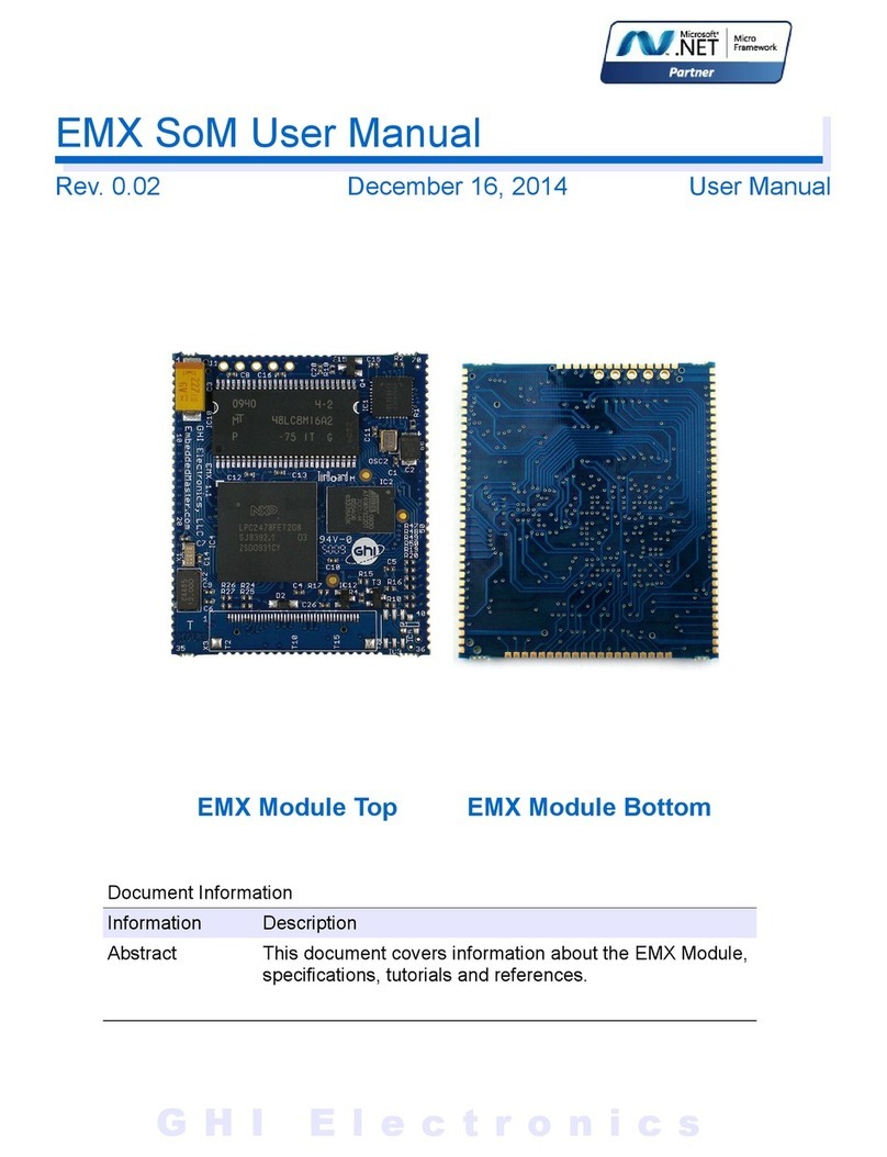
G400-S Top G400-S Bottom
G400-D Top

GHI Electronics,LL G400 SoM User Manual
Rev 0.07 Page 2 of 72 www.GHIElectronics.com
Revision History
Rev No. Date Modification
Rev 0.07 05/04/15 larified absence of analog output.
Rev 0.06 02/17/15 More UART map enhancements
Rev. 0.05 12/23/14 UART map enhancements
Rev. 0.04 12/23/14 Pin PA11 & SAM-BA
Rev. 0.03 12/23/14 Pin clarification PA11, PA12, PA13, PA9,PA25
Rev. 0.02 11/24/14 larified some Pin descriptions (Ethernet, etc.)
Rev. 0.01 08/26/14 Preliminary version

GHI Electronics,LL G400 SoM User Manual
Table of ontents
Table of ontents
1.Introduction...................................................................................4
1.1.The .NET Micro Framework................................................4
1.2.GHI Electronics and NETMF...............................................5
1.3. Key Features......................................................................6
1.4.Example Applications..........................................................6
2.The Hardware...............................................................................7
2.1.The SAM9X35 Microcontroller............................................7
2.2.SDRAM................................................................................7
2.3.FLASH.................................................................................7
2.4.G400 Products.....................................................................7
3.Pin-Out Description.......................................................................8
3.1.G400-S Pin-out Table..........................................................8
3.2.G400-D Pin-out Table........................................................12
4.Booting. Sequence and ontrol..................................................18
4.1.Boot Mode Pins.................................................................18
4.2.GHI Boot Loader vs. TinyBooter vs. G400 Firmware
(NETMF/Tiny LR)...................................................................19
4.3.Physical Bus Used During Programming, “the Debug
Access Interface”.....................................................................20
5.The GHI Boot Loader..................................................................21
5.1.Updating TinyBooter..........................................................21
5.2.Steps for Using “Update” (SAM-BA):................................21
6.TinyBooter...................................................................................24
6.1.Tiny LR (firmware) Update With FEZ onfig
(Recommended)......................................................................25
6.2.Firmware Update Using MFDeploy (Deprecated).............26
7.NETMF Tiny LR (firmware).......................................................30
7.1.Assemblies and Version Matching....................................30
7.2.Deploying to the Emulator.................................................31
7.3.Deploying to the G400.......................................................35
7.4.Targeting Different Versions of the Framework.................35
8.The Libraries...............................................................................36
8.1.Finding NETMF Library Documentation............................37
8.2.Loading Assemblies...........................................................38
8.3.Digital Inputs/Outputs........................................................39
Interrupt Pins.....................................................................42
8.4. Analog Inputs/Outputs......................................................43
8.5.PWM..................................................................................43
8.6.Signal Generator...............................................................44
8.7.Signal apture...................................................................45
8.8.Serial Port (UART).............................................................46
8.9.SPI.....................................................................................47
8.10.I2 ...................................................................................48
8.11. AN.................................................................................49
8.12.One-wire..........................................................................50
8.13.Graphics..........................................................................51
Fonts..................................................................................52
Glide..................................................................................52
Touch Screen....................................................................53
8.14.USB Host.........................................................................54
8.15.Accessing Files and Folders...........................................55
SD/MM Memory..............................................................57
USB Mass Storage............................................................57
8.16.Secure Networking (T P/IP)...........................................57
The Extensions..................................................................57
MA address setting.........................................................57
IP address (DH P or static):.............................................58
Ethernet.............................................................................58
Wireless LAN WiFi............................................................60
8.17.PPP..................................................................................61
8.18.USB lient (Device) ........................................................62
8.19.Extended Weak References (EWR)................................64
8.20.Real Time lock..............................................................64
8.21.Watchdog.........................................................................66
8.22.Power ontrol..................................................................66
8.23.In-Field Update................................................................66
8.24.SQLite Database.............................................................67
9.Advanced use of the Microprocessor ........................................69
9.1.Register.............................................................................69
9.2.AddressSpace...................................................................69
9.3.Runtime Loadable Procedure............................................69
10.design onsideration................................................................70
10.1.Required Pins..................................................................70
10.2.SPI hannels...................................................................70
10.3.Watchdog.........................................................................70
11.Soldering the G400...................................................................71
Legal Notice...................................................................................72
Licensing..................................................................................72
Disclaimer................................................................................72
Page 3 of 72 www.ghielectronics.com

GHI Electronics,LL G400 SoM User Manual
Introduction
1. Introduction
The G400 is a powerful, yet low-cost, surface-mount System on Module (SoM) running the
.NET Micro Framework software, which enables the SoM to be programmed from Microsoft's
Visual Studio, by simply using a USB cable. Programming in a modern managed language,
such as # and Visual Basic, allows developers to accomplish much more work in less time
by taking advantage of the extensive built-in libraries for networking, file systems, graphical
interfaces and many peripherals.
A simple two layer circuit, with just power and some connectors, can utilize the G400 to bring
the latest technologies to any products. There are no additional licensing or fees and all the
development tools and SDKs are provided freely.
1.1. The .NET Micro Framework
Inspired by its full .NET Framework, Microsoft developed a lightweight version called .NET
Micro Framework (NETMF).
NETMF focuses on the specific requirements of resource-constrained embedded systems.
Development, debugging and deployment is conveniently performed using Microsoft's
powerful Visual Studio tools, all through standard USB cable.
Programming is done in # or Visual Basic. This includes libraries to cover sockets for
networking, modern memory management with garbage collector and multitasking services.
In addition to supporting standard .NET features, NETMF has embedded extensions
supporting:
●General Purpose IO (GPIO with interrupt handling
●Analog input/output
●Standard buses such I2 , SPI, USB, Serial (UART)
●PWM
●Networking
●File System
●Display graphics, supporting images, fonts and controls.
Rev 0.07 Page 4 of 72 www.GHIElectronics.com

GHI Electronics,LL G400 SoM User Manual
Introduction
1.2. GHI Electronics and NETMF
For years, GHI Electronics has been the lead Microsoft partner on .NET Micro Framework
(NETMF). The core NETMF was also extended with new exclusive libraries for an additional
functionality, such as database, USB Host and WiFi.
One of the important extensions by GHI Electronics is Runtime Loadable Procedures (RLP),
allowing native code (Assembly/ ) to be compiled and loaded right from withing managed
code ( #/Visual Basic) to handle time critical and processor intensive tasks. IT can also be
used to add new native extensions to the system.
As for networking, WiFi and PPP libraries are added by GHI Electronics to the NETMF core.
ombined with Ethernet and the other managed services, it is a complete toolbox for the
internet of things.
All the mentioned features are loaded and tested on the G400. GHI Electronics continuously
maintains, upgrades and solves any of the issues on the G400's firmware, to provide regular
and free releases. Users can simply load the new software on the G400 using USB or Serial,
and even use the in-field-update feature. This feature allows the upgrade to be done through
any of the available interface, including file system and networking.
Rev 0.07 Page 5 of 72 www.GHIElectronics.com

GHI Electronics,LL G400 SoM User Manual
Introduction
1.3. Key Features
●.NET Micro Framework
●400Mhz ARM 926EJ-S processor
●128MB RAM
●4MB MB FLASH
●Embedded L D controller
●102 GPIO Pins
●102 Interrupt Inputs
●2 SPI
●I2
●8 UART
●2 AN hannels
●up to 12 10-Bit Analog Inputs
●10-Bit Analog Output
●4Bit SD/SDH /MM Memory card
interface
●4 PWM
●160 mA max
●60 mA Hibernate Mode
●-40º to +85º Operational
●RoHS Lead Free
●T P/IP Stack (.NET sockets)
●SSL secure networking
●WiFi
●PPP
●One-wire on all IOs
●USB Host/Device
●Graphics (image, font and controls)
●SQLite database
●File System (SD and USB Sticks)
●Native extensions RLP
●Real Time lock
●In-Field-update
●Dimensions: (32.05mm x 67.49mm x
4.84mm )
1.4. Example Applications
●Vending machines, POS Terminals
●Measurement tools and testers
●Networked sensors
●Robotics
●entral alarm system
●Smart appliances
●Industrial automation devices
Rev 0.07 Page 6 of 72 www.GHIElectronics.com

GHI Electronics,LL G400 SoM User Manual
The Hardware
2. The Hardware
The G400 core components includes the processor, 4MB flash, and 128MB RAM.
The small, 38.1 x 26.7 x 3.55 mm, module contains everything needed to run a complex
embedded-system in a cost-effective and flexible solution. All needed is a 3.3V power source
and some connections to take advantage of the G400's long list of available features.
2.1. The SAM9X35 Microcontroller
The SAM9X35 microcontroller in the G400 is an 400Mhz, 32Bit, 926EJ-S ARM architecture. It
incorporates:
●16KB Data and Instruction aches
●internal 32KB SRAM, single-cycle at system speed
The NETMF core libraries, combined with the GHI Electronics extensions, provide a long list
of methods to access the available peripherals.
2.2. SDRAM
128MB of SDRAM comes standard with the G400
2.3. FLASH
4MB flash is available on the G400. One of the library extensions provided allows the user
application to be updated in field, even remotely (see Runtime Loadable Procedure.)
2.4. G400 Products
heck the online GHI catalog for our current product line. This section is based on products
available when this manual was initially published.
G400-D: form factor - SODIMM, has on-board Ethernet PHY
G400-S: form factor - surface-mount
FEZ Raptor: form factor - .NET Gadgeteer mainboard.
Rev 0.07 Page 7 of 72 www.GHIElectronics.com

GHI Electronics,LL G400 SoM User Manual
Pin-Out Description
3. Pin-Out Description
Many signals on the G400 are multiplexed to offer multiple functions on a single pin.
Developers can decide on the pin functionality through the provided libraries. These are some
important facts pertaining to the available pins:
●Pins with GPIO feature default to inputs with internal weak pull-up resistors, they are
not 5V tolerant
●Pins are 3.3V levels.
●Advanced details on all pins can be found in the SAM9X35 datasheet from Atmel's
website
urrently there are two different SoMs, the G400-S (surface-mount) and the G400-D (DIMM).
Be sure to reference the correct table below. In particular, note the difference between the
usage pins related to ethernet and power.
3.1. G400-S Pin-out Table
The G400-S does not have an external Ethernet PHY; so the pins are free to use.
G400-S GPIO
Multiplexed
Function(s) Notes
1 PD0
2 PD4
3 DIBP
4 PA27
5 PA16 SD MD
6 PA8 OM4 RX
7 PA3 OM2 TS
8 PA2 OM2 RTS
9 P 28
L D H Sync
OM3 TS
10 P 23
11 P 5 L D Green 0
12 P 1 L D Blue 1
13 VDDIOM1 1.8V
14 SHDN
15 JTAGSEL
16 GND1
17 PB3 ERXDV
18 PB1 ERX1
Rev 0.07 Page 8 of 72 www.GHIElectronics.com

GHI Electronics,LL G400 SoM User Manual
Pin-Out Description
G400-S GPIO
Multiplexed
Function(s) Notes
19 WKUP
20 PB18
21 PB8 AD9
22 PB14 AD3
23 PB12 AD1
24 PB6
EMD
AD7
25 PB15 AD4
26 PB0 ERX0
27 PB5 EMDIO
28 P 2 L D Blue 2
29 P 9
L D Green 4
OM5 RX
30 P 11 L D Red 0
31 P 12 L D Red 1
32 P 24
33 PA0 OM2 TX
34 P 21 PWM3
35 P 19 PWM1
36 P 22
37 PA7 OM4 TX
38 PA4 LDR1 Boot Mode ontrol
39 PB11 AD0
40 PB13 AD2
41 PB10
ETX1
AD11
42 V 3.3V
43 VBAT
44 PB7
ETXEN
AD8
45 PB2 ERXER
46 P 0 L D Blue 0
47 P 6 L D Green 1
48 VDDIOM2 1.8V
49 P 10 L D Green 5
50 P 3 L D Blue 3
51 P 15 L D Red 4
52 P 18 PWM 0
53 VDD ORE1 1.0V
54 P 13 L D Red 2
Rev 0.07 Page 9 of 72 www.GHIElectronics.com

GHI Electronics,LL G400 SoM User Manual
Pin-Out Description
G400-S GPIO
Multiplexed
Function(s) Notes
55 P 31
56 GND2
57 P 26
58 P 30 L D lock
59 PA12 SPI1 MOSI Use as SPI Only
60 PB16 AD5
61 PB17 AD6
62 PB9 ETX0 / AD10
63 PB4 ETX K
64 P 4 L D Blue 4
65 P 7 L D Green 2
66 P 8
L D Green 3
OM5 TX
67 P 14 L D Red 3
68 P 16 OM6 TX
69 P 20 PWM2
70 P 17 OM6 Rx
71 P 27
L D V Sync
OM3 RTS
72 P 29 L D Data Enable
73 PA5 OM3 TX / AN2 TX
74 PA1 OM2 RX
75 PA11 SPI1 MISO Use as SPI Only. Pull low on reset to enter SAM-BA.
For SAM-BA, do not pull low for more than 2
seconds.
76 PA10
OM1 TX
AN1 TX
77 PA9
OM1 RX
AN1 RX Must be HIGH to enter SAM-BA
78 PA15 SD D0
79 PA18 SD D1
80 PA20 SD D3
81 PA23 SPI2 LK
82 PA28
83 PA31 I2 S L Open drain port
84 V 3.3V
85 T K
86 USB D+
87 USB D-
88 USB H0+
Rev 0.07 Page 10 of 72 www.GHIElectronics.com

GHI Electronics,LL G400 SoM User Manual
Pin-Out Description
G400-S GPIO
Multiplexed
Function(s) Notes
89 USB H0-
90 USB H1+
91 USB H1-
92 TDI
93 NRST
94 TMS
95 BMS
96 PWR_EN
97 GND3
98 PA13 SPI1 S K Use as SPI Only
99 PA19 SD D2
100 PA21 SPI2 MISO
101 PA24 LDR0 Boot Mode ontrol
102 PA25 MODE(USB/ OM1#)
103 VDD ORE2 1.0V
104 TDO
105 NTRST
106 PA6
OM3 RX
AN2 RX
107 PA17 SD LK
108 PA22 SPI2 MOSI
109 PA26
110 PA30 I2 SDA Open drain port
111 PA29
112 RT K
113 DIBN
114 PD2
115 PD1
116 PD7
117 PD3
118 PD5
119 PD6
120 GND4
Rev 0.07 Page 11 of 72 www.GHIElectronics.com

GHI Electronics,LL G400 SoM User Manual
Pin-Out Description
3.2. G400-D Pin-out Table
The G400-D board has an external Ethernet PHY, be sure to leave the pins
unconnected to avoid potential damage.
G400-D GPIO
Multiplexed
Function(s) Notes
1 Ground
2 Ethernet TX-
3
4 Ethernet TX+
5 Ground
6 Ethernet RX-
7
8 Ethernet RX
9
10 Ethernet Speed
11 Ethernet Link
12
13 Ground
14
15
16
17
18
19
20 V 3.3V
21
22
23
24
25
26
27 Ground
28
29
30
31
32 V 3.3V
33
34
Rev 0.07 Page 12 of 72 www.GHIElectronics.com

GHI Electronics,LL G400 SoM User Manual
Pin-Out Description
G400-D GPIO
Multiplexed
Function(s) Notes
35 PB3 ERXDV Do not connect. Leave Floating
36 PB4 ETX K Do not connect. Leave Floating
37 PB5 EMDIO Do not connect. Leave Floating
38 PB6
EMD
AD7 Do not connect. Leave Floating
39 PB7
ETXEN
AD8 Do not connect. Leave Floating
40 Ground
41 Ground
42 DIBN
43 DIBP
44 BMS
45 JTAGSEL
46 V 3.3V
47 PB2 ERXER Do not connect. Leave Floating
48 PB9
ETX0
AD10 Do not connect. Leave Floating
49 PB10
ETX1
AD11 Do not connect. Leave Floating
50 PB0 ERX0 Do not connect. Leave Floating
51 Ground
52 PB1 ERX1 Do not connect. Leave Floating
53
54
55
56
57 PD18
58 PD17
59 PD16
60 V 3.3V
61 PD15
62 PD14
63 PD13
64 PD12
65 Ground
66 PD11
67 PD10
68 PD9
69 PD8
70
Rev 0.07 Page 13 of 72 www.GHIElectronics.com

GHI Electronics,LL G400 SoM User Manual
Pin-Out Description
G400-D GPIO
Multiplexed
Function(s) Notes
71
72 V 3.3V
73
74
75
76
77
78
79 Ground
80
81
82
83 PA14 Do not connect. Leave Floating
84
85 P 25 Do not connect. Leave Floating
86
87
88 V 3.3V
89
90
91 PB8 AD9
92 PD2
93 P 23
94 PD0
95 Ground
96 PB18
97 PB11 AD0
98 PA5
OM3 TX
AN2 TX
99 PA6 OM3 RX/ AN2 RX
100 P 22
101 P 31
102 PA0 OM2 TX
103 PA1 OM2 RX
104 PB12 AD1
105 P 18 PWM0
106 V 3.3V
107 PA11 SPI1 MISO
Use as SPI Only. Pull low on reset to enter SAM-BA.
For SAM-BA, do not pull low for more than 2 seconds.
108 PA12 SPI1 MOSI Use as SPI Only
Rev 0.07 Page 14 of 72 www.GHIElectronics.com

GHI Electronics,LL G400 SoM User Manual
Pin-Out Description
G400-D GPIO
Multiplexed
Function(s) Notes
109 PA13 SPI1 LK Use as SPI Only
110 PB17 AD6
111 PA4 LDR1 Boot Mode ontrol
112 P 19 PWM1
113 Ground
114 PB16 AD5
115 PA30 I2 SDA Open drain port
116 PA31 I2 S L Open drain port
117 PA9
OM1 RX
AN1 RX Must be HIGH to enter SAM-BA mode
118 PA10
OM1 TX
AN1 TX
119 P 24
120 PA2 OM2 RTS
121 PA3 OM2 TS
122 PD7
123 PA15 SD D0
124 V 3.3V
125 PA16 SD MD
126 PA17 SD LK
127 PA18 SD D1
128 PA19 SD D2
129 PA20 SD D3
130 P 21 PWM3
131 Ground
132 P 26
133 P 20 PWM2
134 PA24 LDR0 Boot Mode ontrol
135 PA25 MODE(USB/ OM1#)
136 PA26
137 PA27
138 PA28
139 PA29
140 P 16 OM6 TX
141 P 17 OM6 RX
142 V 3.3V
143 P 27
L D V Sync
OM3 RTS
144 P 28
L D H Sync
OM3 TS
Rev 0.07 Page 15 of 72 www.GHIElectronics.com

GHI Electronics,LL G400 SoM User Manual
Pin-Out Description
G400-D GPIO
Multiplexed
Function(s) Notes
145 P 30 L D lock
146 P 29 L D Data Enable
147 PD3
148 PD4
149 PD5
150 PD6
151 Ground
152 P 0 L D Blue 0
153 P 1 L D Blue 1
154 P 2 L D Blue 2
155 P 3 L D Blue 3
156 P 4 L D Blue 4
157 PB13 AD2
158 PB14 AD3
159 PB15 AD4
160 V 3.3V
161 P 5 L D Green 0
162 P 6 L D Green 1
163 P 7 L D Green 2
164 P 8
L D Green 3
OM5 TX
165 P 9
L D Green 4
OM5 RX
166 PD1
167 PA8 OM4 RX
168 P 15 L D Red 4
169 Ground
170 P 10 L D Green 5
171 P 11 L D Red 0
172 P 12 L D Red 1
173 P 13 L D Red 2
174 P 14 L D Red 3
175 PA23 SPI2 LK
176 PA21 SPI2 MISO
177 WKUP
178 PA22 SPI2 MOSI
179 SHDN
180 V 3.3V
181 PWM_EN
182 USB3 HOST D+
Rev 0.07 Page 16 of 72 www.GHIElectronics.com

GHI Electronics,LL G400 SoM User Manual
Pin-Out Description
G400-D GPIO
Multiplexed
Function(s) Notes
183 VDDBU (VBAT)
184 USB3 HOST D-
185 Ground
186 Ground
187 NRST
188 USB2 HOST D+
189 RT K
190 USB2 HOST D-
191 TDO
192 V 3.3V
193 NTRST
194 USB1 LIENT D+
195 TDI
196 USB1 LIENT D-
197 T K
198 Ground
199 TMS
200 PA7 OM4 TX
Rev 0.07 Page 17 of 72 www.GHIElectronics.com

GHI Electronics,LL G400 SoM User Manual
Booting. Sequence and ontrol
4. Bootin . Sequence And Control
Software on the G400 is divided into different components:
●The GHI Boot loader: Initializes memories and executes TinyBooter. It is also used to
update TinyBooter.
●TinyBooter does set-up and then runs the firmware (Tiny LR, NETMF core, and GHI
extensions). It is also used to update the NETMF firmware and its system
configurations.
●TinyCLR and NETMF (The firmware): interprets and executes the managed
application. It is used for other functions such as loading and/or debugging the
managed application.
●The managed application ( # - Visual Basic); developed by customers.
●Optional: Native RLP routines ( and/or assembly, described in the Runtime Loadable
Procedure section) ; developed by customers.
If the boot mode pins, LDR0 and LDR1, are left floating (internal pull up), or pulled high
externally, the default boot-up sequence executes as the following:
●The GHI Boot loader initializes Flash and RAM memory and looks for a valid
TinyBooter and passes execution to it.
●TinyBooter prepares the G400 hardware resources required by the NETMF ore
environment and passes execution to NETMF Tiny LR.
●If a valid end-user embedded application exists, it gets executed.
4.1. Boot Mode Pins
Default start-up execution can be changed using two control pins, they are active low and
have internal weak pull up resistors:
LDR0 LDR1 Effect
(Ignored) High Default, execute all levels
High Low Execute the Boot Loader and TinyBooter but
do not execute NETMF Tiny LR
Low Low Execute Boot Loader but do not execute
TinyBooter*
* This mode is not currently implemented. It will be added in a future release. Instead, the SAM-BA Monitor is invoked.
heck the Release Note in the SDK, if changes are made they will be noted there.
Rev 0.07 Page 18 of 72 www.GHIElectronics.com

GHI Electronics,LL G400 SoM User Manual
Booting. Sequence and ontrol
4.2. GHI Boot Loader vs. TinyBooter vs. G400 Firmware
(NETMF/Tiny LR)
The table below gives greater detail of the characteristics of each level of execution.
GHI Boot Loader* TinyBooter NETMF Tiny LR (firmware)
Used to update the G400
TinyBooter or for low level
G400 flash maintenance.
Used to update the G400
firmware (NETMF Tiny LR)
and to update system
configurations such as
networking settings.
Used to deploy, execute and
debug the managed NETMF
application code. In other
words, it plays the role of a
virtual machine.
Emergency use or when GHI
releases a new TinyBooter. Sometimes used. Always used.
Pre-burned in the G400's
flash memory. an't be
updated.
Replaceable using the GHI
Boot Loader
Replaceable; under control of
TinyBooter
ontrolled through simple text
commands and X-modem.
Any terminal, such as
teraterm or hyper terminal,
can be used.
ontrolled through MFDeploy
or FEZ onfig tools.
Runs the user application and
accepts commands from
Visual Studio for debugging
purposes.
* * This mode is not currently implemented. It will be added in a future release. Instead, the SAM-BA Monitor is invoked.
heck the Release Note in the SDK, if changes are made they will be noted there.
When applying updates, the lowest level software should be updated first. For example, if
both the firmware (Tiny LR) and TinyBooter need updates, TinyBooter should be updated
first.
Serial communications parameters are: 152000 baud, 8-bit data with one stop bit and no
parity.
Rev 0.07 Page 19 of 72 www.GHIElectronics.com

GHI Electronics,LL G400 SoM User Manual
Booting. Sequence and ontrol
4.3. Physical Bus Used During Programming, “the Debug Access
Interface”
The communication between a P and the various loaders is over USB or UART (serial port).
This, “Debug Access Interface,” is used for updating, deploying or debugging the software
components.
The MODE Pin (PA25) is used to select between USB and serial. The pin is internally pulled
up. So high or unconnected will give you USB debugging, pulling it low will give you serial
debugging on OM1.
If a direct connection exists between the G400's UART and another UART based device a
null modem (cross-over cable) is needed. If connecting to an RS232 device, such as a true
OM port on a P , a RS232 to/from TTL level converter is required.
When USB is selected, the drivers needed on the P are included in the GHI SDK. Two
different drivers are available. The first one is a virtual OM driver used by the GHI loader.
The second one is used by TinyBooter and the NETMF firmware.
NOTE: When entering SAM-BA PA9 should be HIGH.
Rev 0.07 Page 20 of 72 www.GHIElectronics.com
This manual suits for next models
1
Table of contents
Other GHI electronics Control Unit manuals