GHI electronics EMX User manual

GHI Electronics
EMX SoM User Manual
Rev. 0.02 December 16, 2014 User Manual
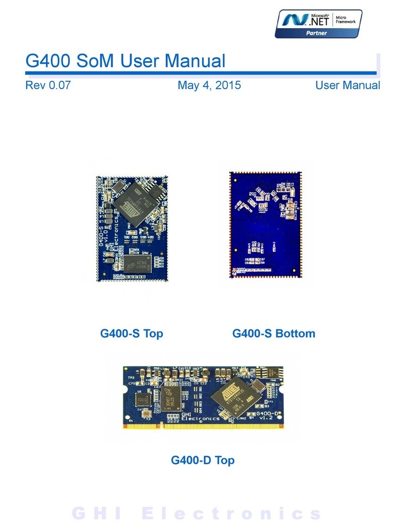
EMX Module Top EMX Module Bottom
Document Information
Information Descri tion
Abstract This document covers information about the EMX Module,
s ecifications, tutorials and references.

GHI Electronics,LLC EMX SoM User Manual
Table of Contents
Table of Contents
1.Introduction...................................................................................4
1.1.The .NET Micro Framework................................................4
1.2.GHI Electronics and NETMF...............................................5
1.3.EMX Module Key Features.................................................6
1.4.Exam le A lications..........................................................6
2.The Hardware...............................................................................7
2.1.LPC2478 Microcontroller.....................................................7
2.2.SDRAM................................................................................7
2.3.FLASH.................................................................................7
3.Pin-Out Descri tion.......................................................................8
3.1.Pin-out Table........................................................................8
4.EMX on boot u ..........................................................................13
4.1.Boot Mode Pins.................................................................13
4.2.GHI Boot Loader vs. TinyBooter vs. EMX Firmware
(NETMF/TinyCLR)...................................................................15
4.3.The Loader and Firmware Debug Access Interface..........15
5.The GHI Boot Loader..................................................................16
5.1.The Commands.................................................................16
5.2.U dating TinyBooter..........................................................16
U dating TinyBooter using FEZ Config.............................17
U dating EMX Manually....................................................18
Loading using XMODEM...................................................18
5.3.TinyBooter.........................................................................21
5.4.TinyCLR (firmware) U date Using FEZ Config.................22
5.5.Firmware U date Using MFDe loy...................................23
6.NETMF TinyCLR (firmware).......................................................26
6.1.Assemblies Version Matching...........................................26
6.2.De loying to the Emulator.................................................27
6.3.De loying to the EMX Module...........................................28
6.4.Targeting Different Versions of the Framework.................30
7.The Libraries...............................................................................31
7.1.Finding NETMF Library Documentation............................32
7.2.Loading Assemblies...........................................................33
7.3.Im ortant Information for the Following Exam les............34
7.4.Digital In uts/Out uts (GPIO)............................................34
Out uts..............................................................................35
In uts.................................................................................37
Interru t Pins.....................................................................38
7.5. Analog In uts/Out uts......................................................39
7.6.PWM..................................................................................39
7.7.Signal Generator...............................................................40
7.8.Signal Ca ture...................................................................41
7.9.Serial Port (UART).............................................................42
7.10.SPI...................................................................................43
7.11.I2C...................................................................................44
7.12.CAN.................................................................................45
7.13.One-wire..........................................................................46
7.14.Gra hics..........................................................................47
Fonts..................................................................................48
Glide..................................................................................48
Touch Screen....................................................................49
7.15.USB Host.........................................................................50
7.16.Accessing Files and Folders...........................................51
SD/MMC Memory..............................................................53
USB Mass Storage............................................................53
7.17.Secure Networking (TCP/IP)...........................................53
The Extensions..................................................................53
MAC address setting.........................................................53
IP address (DHCP or static):.............................................54
Ethernet.............................................................................55
Wireless LAN WiFi............................................................56
7.18.PPP..................................................................................57
7.19.USB Client (Device) ........................................................57
7.20.Extended Weak References (EWR)................................59
7.21.Real Time Clock..............................................................59
7.22.Watchdog.........................................................................61
7.23.Power Control..................................................................61
7.24.In-Field U date................................................................63
7.25.SQLite Database.............................................................63
8.Advanced use of the Micro rocessor ........................................65
8.1.Register.............................................................................65
8.2.AddressS ace...................................................................65
8.3.Battery RAM......................................................................65
8.4.Runtime Loadable Procedure............................................66
9.design Consideration..................................................................67
Required Pins....................................................................67
Interru t Pins.....................................................................67
...........................................................................................67
10.Soldering EMX..........................................................................68
Legal Notice...................................................................................69
Licensing..................................................................................69
Disclaimer................................................................................69
EMX Module Page 3 of 69 www.ghielectronics.com

GHI Electronics,LLC EMX SoM User Manual
Introduction
1. Introduction
The EMX Module is a owerful, yet low-cost, surface-mount System on Module (SoM)
running the .NET Micro Framework software, which enables the SoM to be rogrammed from
Microsoft's Visual Studio, by sim ly using a USB cable. Programming in a modern managed
language, such as C# and Visual Basic, allows develo ers to accom lish much more work in
less time by taking advantage of the extensive built-in libraries for networking, file systems,
gra hical interfaces and many eri herals.
With just ower and some connectors, develo ers can utilize the EMX Module to bring the
latest technologies to any roducts. There are no additional licensing or fees and all the
develo ment tools and SDKs are rovided freely.
1.1. T e .NET Micro Framework
Ins ired by its full .NET Framework, Microsoft develo ed a lightweight version called .NET
Micro Framework (NETMF).
NETMF focuses on the s ecific requirements of resource-constrained embedded systems.
Develo ment, debugging and de loyment is conveniently erformed using Microsoft's
owerful Visual Studio tools, all through standard USB cable.
Programming is done in C# or Visual Basic. This includes libraries to cover sockets for
networking, modern memory management with garbage collector and multitasking services.
In addition to su orting standard .NET features, NETMF has embedded extensions
su orting:
●General Pur ose IO (GPIO with interru t handling
●Analog in ut/out ut
●Standard buses such I2C, SPI, USB, Serial (UART)
●PWM
●Networking
●File System
●Dis lay gra hics, su orting images, fonts and controls.
Rev. 0.02 Page 4 of 69 www.GHIElectronics.com

GHI Electronics,LLC EMX SoM User Manual
Introduction
1.2. GHI Electronics and NETMF
For years, GHI Electronics has been the lead Microsoft artner on .NET Micro Framework
(NETMF). The core NETMF was also extended with new exclusive libraries for an additional
functionality, such as database, USB Host and WiFi.
One of the im ortant extensions by GHI Electronics is Runtime Loadable Procedures (RLP),
allowing native code (Assembly/C) to be com iled and loaded right from withing managed
code (C#/Visual Basic) to handle time critical and rocessor intensive tasks. IT can also be
used to add new native extensions to the system.
As for networking, WiFi and PPP libraries are added by GHI Electronics to the NETMF core.
Combined with Ethernet and the other managed services, it is a com lete toolbox for the
internet of things.
All the mentioned features are loaded and tested on the EMX Module. GHI Electronics
continuously maintains, u grades and solves any of the issues on the EMX Module firmware,
to rovide regular and free releases. Users can sim ly load the new software on the EMX
Module using USB or Serial, and even use the in-field-u date feature. This feature allows the
u grade to be done through any of the available interface, including file system and
networking.
Rev. 0.02 Page 5 of 69 www.GHIElectronics.com

GHI Electronics,LLC EMX SoM User Manual
Introduction
1.3. EMX Module Key Features
●.NET Micro Framework
●72 Mhz 32-bit ARM7
●16 MB RAM
●4.5 MB FLASH
●Embedded LCD controller
●76 GPIO Pins
●43 Interru t In uts
●2 SPI
●I2C
●4 UART
●2 CAN Channels
●7 10-Bit Analog In ut
●10-Bit Analog Out ut
●4Bit SD/MMC Memory card interface
●6 PWM
●Power 200 / 160 / 40 mA
●-40ºC to +85ºC O erational
●RoHS Lead Free
●45.75 x 39.4 x 4.4 mm
●TCP/IP Stack (.NET sockets)
●SSL secure networking
●WiFi
●PPP
●USB Host & Client
●Gra hics (image, font and controls)
●SQLite database
●File System (SD and USB Sticks)
●Native extensions RLP
1.4. Example Applications
●Vending machines, POS Terminals
●Measurement tools and testers
●Networked sensors
●Robotics
●Central alarm system
●Smart a liances
●Industrial automation devices
●Designs with intensive rocessing or time-critical routines (using RLP)
●GPS navigation
●Medical instrument (with a color touch screen dis lay).
Rev. 0.02 Page 6 of 69 www.GHIElectronics.com

GHI Electronics,LLC EMX SoM User Manual
The Hardware
2. The Hardware
The EMX Module core com onents includes the rocessor, 4.5MB flash, and 16MB RAM.
The small, 38.1 x 26.7 x 3.55 mm (only 1 x 1.5 inches), module contains everything needed to
run a com lex embedded-system in a cost-effective and flexible solution. All needed is a 3.3V
ower source and some connections to take advantage of the EMX Module's long list of
available features.
2.1. LPC2478 Microcontroller
The LPC2478 microcontroller in the EMX Module is an 72Mhz, 32Bit, ARM7. The LPC2478
contains a memory acceleration interface with 128Bit internal FLASH memory. This lets the
rocessor core run with zero wait states. Com aring to executing code from 16Bit external
FLASH we see over 10 times the execution s eed. The internal FLASH is 0.5MB that is used
to run the com lete .NET Micro Framework core very efficiently. Also, the rocessor includes
an RTC that can o erate while while the rocessor is off. The EMX Module already has the
needed circuitry to run the RTC. Users only need to add a battery or a su er ca acitor to
VBAT in.
The LPC2478 has a wide range of eri herals that adds a lot of functions and features to
EMX such as PWM, GPIO, LCD Controller, USB HC, etc.
The NETMF core libraries, combined with the GHI Electronics extensions, rovide a long list
of methods to access the available eri herals.
2.2. SDRAM
16MB of SDRAM comes standard with the EMX Module.
2.3. FLASH
4.5MB of external flash is available on the EMX Module. The fast zero-wait-state internal
0.5MB is used to execute the core services of the system to achieve the highest ossible
erformance. The remaining 4MB of external memory is used to hold more extensions and to
store the user's end a lication. About 1MB of the external FLASH is used for boot loader,
system assemblies and other internal GHI resources. About 3MB is reserved for de loyed
managed a lications, including resources. 256KB is reserved for two EWR (Extended Week
References) regions, each region being 128KB and one of them is reserved for CLR use.
One of GHI's extensions allows a lications to be u dated in field, even remotely.
Rev. 0.02 Page 7 of 69 www.GHIElectronics.com

GHI Electronics,LLC EMX SoM User Manual
Pin-Out Descri tion
3. Pin-Out Description
Many signals on the EMX Module are multi lexed to offer multi le functions on a single in.
Develo ers can decide on the in functionality through the rovided libraries. These are some
im ortant facts ertaining to the available ins:
●Pins with GPIO feature default to in uts with internal weak ull-u resistors
●GPIO ins are 3.3V levels but 5V tolerant
●Pins with analog feature are not 5V tolerant when the analog function is used
●Only GPIO ins on orts 0 and 2 are interru t ca able
●Advanced details on all ins can be found in the LPC2478 datasheet
Most signals on EMX are multi lexed to offer more than one function for every in. It is u to
the develo er to select which one of the functions to use. GHI drivers and .NET Micro
Framework does checking to make sure the user is not trying to use two functions on the
same in. The develo er should still understand what functions are multi lexed so there is no
conflict. For exam le, analog channel 3 (ADC3) and the analog out ut (AOUT) are on the
same in IO7.
3.1. Pin-out Table
No. LPC2478
H/W Name
EMX IO 2nd Feature EMX Module
Pin Descri tion
1 3.3V Connect to 3.3 volt source.
2 GND Connect to Ground.
3 P0.4 IO0* CAN2/
Boot control
RD CAN Channel 2 Data Receive in (In). TinyBooter/Firmware Control (with 7, and 53)
4 P0.5 IO1* CAN2 TD CAN Channel 2 Data Transmit in (Out).
5 P0.3 IO2 * COM1 Serial ort (UART) RXD receive signal (In) for COM1.
6 P0.2 IO3* COM1 Serial ort (UART) TXD transmit signal (Out) for COM1.
7 P2.5 IO4* Boot Control General ur ose digital I/O. TinyBooter/Firmware Control (with 3, and 53)
8 P0.24 IO5* ADC1/
Touch_Y_UP
ADC1 (10Bit Analog to Digital In ut)
or Touch Screen Y-axis U analog signal.
Rev. 0.02 Page 8 of 69 www.GHIElectronics.com

GHI Electronics,LLC EMX SoM User Manual
Pin-Out Descri tion
No. LPC2478
H/W Name
EMX IO 2nd Feature EMX Module
Pin Descri tion
1 3.3V Connect to 3.3 volt source.
9 P0.25 IO6* ADC2/
COM4
ADC2 (10Bit Analog to Digital In ut)
or Serial ort (UART) TXD transmit signal (Out) for COM4.
10 P0.26 IO7* ADC3/ DAC/
COM4
ADC3 (10Bit Analog to Digital In ut) or DAC (Digital to Analog Out ut)
or Serial ort (UART) RXD receive signal (In) for COM4.
11 P0.23 IO8* ADC0/
Touch_X_Lef
t
ADC0 (10Bit Analog to Digital In ut)
or Touch Screen X-axis Left analog signal.
12 P4.29 IO9 N/A General ur ose digital I/O
13 P4.28 IO10
14 P0.28 IO11* I2C (open drain pin) I2C Interface SCL
15 P0.27 IO12* I2C (open drain pin) I2C Interface SDA
16 P3.16 IO13 PWM0 PWM0 (Pulse Width Modulation Out ut) LPC2478 PWM Timer 0.
17 P3.24 IO14 PWM1 PWM1 (Pulse Width Modulation Out ut) LPC2478 PWM Timer 1.
18 P3.25 IO15 N/A General ur ose digital I/O
19 P1.19 IO16 N/A General ur ose digital I/O
20 P2.21 IO17* N/A General ur ose digital I/O
21 P0.11 IO18* N/A General ur ose digital I/O
22 P2.22 IO19* N/A General ur ose digital I/O
23 P0.1 IO20* CAN1 TD CAN Channel 1 Data Transmit in (Out)
24 P0.10 IO21* N/A General ur ose digital I/O.
25 P0.0 IO22* CAN1 RD CAN Channel 1 Data Receive in (In)
26 P1.30 N/A USB_VBUS1USB device ower detect signal. Connect to ower in on USB device.
27 P2.10 IO23* N/A General ur ose digital I/O
28 RTC_VBAT Connect to 3.3 volt backu battery to kee the real-time clock running.
29 USBD- USB Host Feature USB negative data line of the USB hosting feature.
30 USBD+ USB Host Feature USB ositive data line of the USB hosting feature.
31 P0.12 IO45* ADC6 ADC6 (10Bit Analog to Digital In ut).
32 P0.13 IO46* ADC7 ADC7 (10Bit Analog to Digital In ut).
33 P1.31 IO47 ADC5 ADC5 (10Bit Analog to Digital In ut).
34 3.3V Connect to 3.3 volt source.
35 P3.27 IO48 PWM4 PWM4 (Pulse Width Modulation Out ut) LPC2478 PWM Timer 1.
36 GND Connect to Ground.
37 3.3V Connect to 3.3 volt source.
Rev. 0.02 Page 9 of 69 www.GHIElectronics.com

GHI Electronics,LLC EMX SoM User Manual
Pin-Out Descri tion
No. LPC2478
H/W Name
EMX IO 2nd Feature EMX Module
Pin Descri tion
1 3.3V Connect to 3.3 volt source.
38 N/C Not Connected.
39 P3.26 IO49 PWM3 PWM3 (Pulse Width Modulation Out ut) LPC2478 PWM Timer 1.
40 P3.17 IO50 PWM2 PWM2 (Pulse Width Modulation Out ut) LPC2478 PWM Timer 0.
41 USBD- device USB negative data line of the USB debugging interface and for the USB client feature.
42 USBD+ device USB ositive data line of the USB debugging interface and for the USB client feature.
43 Ethernet RD- Ethernet receive data minus.
Recommended Ethernet connector is
J0011D01BNL.
Ethernet PHY is not needed since it is
embedded in EMX hardware.
44 Ethernet RD+ Ethernet receive data lus.
45 Ethernet TD- Ethernet transmit data minus.
46 Ethernet TD+ Ethernet transmit data lus.
47 P0.18 IO24* SPI1 SPI master bus interface MOSI signal (Master Out Slave In) for SPI1.
48 P0.17 IO25* SPI1 SPI master bus interface MISO signal (Master In Slave Out) for SPI1.
49 P0.16 IO26* N/A General ur ose digital I/O.
50 P0.15 IO27* SPI1 SPI master bus interface SCK signal (Clock)for SPI1.
51 P4.23 IO28 COM3 Serial ort (UART) RXD receive signal (In) for COM3.
52 P4.22 IO29 COM3 Serial ort (UART) TXD transmit signal (Out) for COM3.
53 P2.11 IO30* Boot Control General ur ose digital I/O. TinyBooter/Firmware Control (with 7, and 3)
54 P3.30 IO31 COM2 Serial ort (UART) RTS hardware handshaking signal for COM2.
55 P2.1 IO32* COM2 Serial ort (UART) RXD receive signal (IN) for COM2.
56 P0.6 IO33* N/A General ur ose digital I/O.
57 P3.18 IO34 COM2 Serial ort (UART) CTS hardware handshaking signal for COM2.
58 P0.7 IO35* SPI2 SPI master bus interface SCK signal (Clock)for SPI2.
59 P0.9 IO36* SPI2 SPI master bus interface MOSI signal (Master Out Slave In) for SPI2.
60 P2.0 IO37* COM2 Serial ort (UART) TXD transmit signal (Out) for COM2.
61 P0.8 IO38* SPI2 SPI master bus interface MISO signal (Master In Slave Out) for SPI2.
62 P1.12 IO39 SD_DAT3 SD card 4Bit data bus, data line no. 3.
63 P1.11 IO40 SD_DAT2 SD card 4Bit data bus, data line no. 2.
64 P1.7 IO41 SD_DAT1 SD card 4Bit data bus, data line no. 1.
65 P1.2 IO42 SD_CLK SD card 4Bit data bus, clock line.
66 P1.6 IO43 SD_DAT0 SD card 4Bit data bus, data line no. 0.
67 P1.3 IO44 SD_CMD SD card 4Bit data bus, command line.
68 SD_PWR SD memory ower (connect directly to SD socket ower in).
69 GND Connect to Ground.
Rev. 0.02 Page 10 of 69 www.GHIElectronics.com

GHI Electronics,LLC EMX SoM User Manual
Pin-Out Descri tion
No. LPC2478
H/W Name
EMX IO 2nd Feature EMX Module
Pin Descri tion
1 3.3V Connect to 3.3 volt source.
70 RESET# Hardware reset signal, Reset state is on Low.
T1 P2.12 IO69* LCD R0 TFT Dis lay, Red signal bit 0.
T2 P2.6 IO65* LCD R1 TFT Dis lay, Red signal bit 1.
T3 P2.7 IO66* LCD R2 TFT Dis lay, Red signal bit 2.
T4 P2.8 IO67* LCD R3 TFT Dis lay, Red signal bit 3.
T5 P2.9 IO68* LCD R4 TFT Dis lay, Red signal bit 4.
T6 P1.20 IO51 LCD G0 TFT Dis lay, Green signal bit 0.
T7 P1.21 IO52 LCD G1 TFT Dis lay, Green signal bit 1.
T8 P1.22 IO53 LCD G2 TFT Dis lay, Green signal bit 2.
T9 P1.23 IO54 LCD G3 TFT Dis lay, Green signal bit 3.
T10 P1.24 IO55 LCD G4 TFT Dis lay, Green signal bit 4.
T11 P1.25 IO56 LCD G5 TFT Dis lay, Green signal bit 5.
T12 P2.13 IO70* LCD B0 TFT Dis lay, Blue signal bit 0.
T13 P1.26 IO57 LCD B1 TFT Dis lay, Blue signal bit 1.
T14 P1.27 IO58 LCD B2 TFT Dis lay, Blue signal bit 2.
T15 P1.28 IO59 LCD B3 TFT Dis lay, Blue signal bit 3.
T16 P1.29 IO60 LCD B4 TFT Dis lay, Blue signal bit 4.
T17 P2.2 IO61* LCD CLK TFT Dis lay, Clock.
T18 P2.4 IO63* LCD EN TFT Dis lay, Enable.
T19 P2.5 IO64* LCD
H-Sync
TFT Dis lay, Horizontal sync.
T20 P2.3 IO62* LCD
V-Sync
TFT Dis lay, Vertical sync.
J1 ALARM The alarm in is an RTC controlled out ut. This is a 1.8 V in.
J2 P3.23 IO71 LMODE General ur ose digital I/O is used to choose the access interface for EMX between USB
(Low) or COM1(High or not connected) on startu (refer to EMX access interface section).
J3 P2.23 IO72* T_X_Right Touch Screen X-axis Right digital out ut signal.
J4 P3.31 IO73 T_Y_Down Touch Screen Y-axis Down digital out ut signal.
J5 P3.29 IO74 PWM5 PWM5 (Pulse Width Modulation Out ut) LPC2478 PWM Timer 1 .
J6 P4.31 IO75 N/A General ur ose digital I/O
J7 JTAG TMS JTAG TMS signal.
J8 JTAG TCK JTAG TCK signal.
Rev. 0.02 Page 11 of 69 www.GHIElectronics.com

GHI Electronics,LLC EMX SoM User Manual
Pin-Out Descri tion
No. LPC2478
H/W Name
EMX IO 2nd Feature EMX Module
Pin Descri tion
1 3.3V Connect to 3.3 volt source.
J9 JTAG TDO JTAG TDO signal.
J10 JTAG TRST JTAG TRST signal.
J11 JTAG RTCK JTAG RTCK signal.
J12 JTAG TDI JTAG TDI signal.
J13 Ethernet S eed Connect to Ethernet Connector S eed LED.
High = 100 Mb s
Low = 10 Mb s
J14 Ethernet Link Connect to Ethernet Connector Link LED.
High = Ethernet activity.
J15 GND Connect to Ground.
* Interru t ca able in ut.
Rev. 0.02 Page 12 of 69 www.GHIElectronics.com

GHI Electronics,LLC EMX SoM User Manual
EMX on boot u
4. EM On Boot Up
Software run on the EMX Module is divided into different com onents:
●The GHI Boot loader – initializes memories and executes TinyBooter. It is also used to
u date TinyBooter.
●TinyBooter – does set-u for, and then, loads the firmware (TinyCLR, NETMF core,
and GHI extensions). It is also used to u date the NETMF firmware and its system
configurations.
●TinyCLR and NETMF (the firmware) -- inter rets and executes the managed
application. It is used for other functions such as loading and/or debugging the
managed application.
●The managed application (C# - Visual Basic) – develo ed by customers.
●O tional: Native RLP routines (C and/or assembly, described in the Runtime Loadable
Procedure section); develo ed by customers.
If the boot mode ins, 7 and 3, are left floating (internal ull u ), or ulled high externally, the
default boot-u sequence executes as the following (see also, the flow-chart further below):
●The GHI boot loader initializes Flash and RAM memory and looks for a valid
TinyBooter and asses execution to it.
●TinyBooter re ares the EMX hardware resources required by the NETMF Core
environment and asses execution to NETMF TinyCLR.
●If a valid end-user embedded a lication exists, it gets executed.
4.1. Boot Mode Pins
Default start-u execution can be changed using two control ins, they are active low and
have internal weak ull u resistors:
Pin 7 Pin 3 Pin 53 Effect
High or
unconnected
High or
unconnected
High or
unconnected Default, execute all levels
Low Low Low Execute Boot Loader but do not execute
TinyBooter
Low Low High or
unconnected
Execute the Boot Loader and TinyBooter
but do not execute NETMF TinyCLR
Rev. 0.02 Page 13 of 69 www.GHIElectronics.com

GHI Electronics,LLC EMX SoM User Manual
EMX on boot u
The following flow chart clearly ex lains the boot u sequence:
Rev. 0.02 Page 14 of 69 www.GHIElectronics.com
A lication rogram exits
Execute a lication rogram
Valid a lication code?
Access EMX firmware
Valid EMX firmware
(TinyCLR?)
Access TinyBooter
Valid TinyBooter?
Access GHI Boot Loader
Are 7 and 3
Low? And 53 High?
EMX Boot-U Sequence
Flow Chart
No
No
Yes
No
7, 3, 53 low?
Yes
Stay in EMX firmware and wait
for an action through Visual C# or other
de loyment and/or control tool.
A lication loader and debugger level.
Stay in TinyBooter and U date
Firmware with FEZ Config.
or MFDe loy.
Wait for GHI boot loader; u date
TinyBooter with FEZ Config
or through terminal service
rogram.
System Power U

GHI Electronics,LLC EMX SoM User Manual
EMX on boot u
4.2. GHI Boot Loader vs. TinyBooter vs. EMX Firmware
(NETMF/TinyCLR)
The table below gives greater detail of the characteristics of each level of execution.
GHI Boot Loader TinyBooter NETMF TinyCLR (firmware)
Used to u date EMX
TinyBooter or for low level
EMX flash maintenance.
Used to u date the EMX
firmware (NETMF TinyCLR)
and to u date system
configurations such as
networking settings.
Used to de loy, execute and
debug the managed NETMF
a lication code. In other
words, it lays the role of a
virtual machine.
Emergency use or when GHI
releases a new TinyBooter. Sometimes used. Always used.
Pre-burned into the EMX
Module's flash memory. Can't
be u dated.
Re laceable using FEZ
Config or the GHI Boot
Loader
Re laceable; for exam le,
under control of TinyBooter
Controlled through sim le text
commands and X-modem.
Any terminal, such as
teraterm or hy er terminal,
can be used.
Controlled through MFDe loy
or FEZ Config tools.
Runs the user a lication and
acce ts commands from
Visual Studio for debugging
ur oses.
When a lying u dates, the lowest level software should be u dated first. For exam le, if
both the firmware (TinyCLR) and TinyBooter need u dates, TinyBooter should be u dated
first.
4.3. T e Loader and Firmware Debug Access Interface
The communication between a PC and the EMX Module can be done using a USB ort or a
serial ort (COM1). This interface can be used for u dating, de loying or debugging the
software com onents.
The LMODE Pin is used to select USB vs serial (UART). When LMODE is high or left floating
(internal weak ull u resistor) the system will run in serial mode using COM1; when ulled,
low (10 K resister), USB is used.
When USB is selected, the drivers needed on the PC are included in the GHI SDK. Two
different drivers are available. The first one is a virtual COM driver used by the GHI loader.
The second one is used by TinyBooter and NETMF TinyCLR.
Rev. 0.02 Page 15 of 69 www.GHIElectronics.com

GHI Electronics,LLC EMX SoM User Manual
The GHI Boot Loader
5. The GHI Boot Loader
The EMX Boot Loader software is re-loaded and locked on the EMX Module. It is used to
u date TinyBooter and can be used to do a com lete erase all flash memory. The GHI boot
loader is rarely needed but it is recommended to kee access available in all roject designs.
The GHI boot loader acce ts sim le commands sent with the hel of a terminal service
software, such as TeraTerm or Hy er Terminal. A command character is sent and the boot
loader erforms an action; results are returned in a human friendly format followed by a "BL"
indicating that the boot loader is ready for the next command. All commands and res onses
use ASCII encoded characters.
The EMX on boot u section rovides the required information on how to choose the access
interface and how to access the GHI boot loader.
5.1. T e Commands
Command Description Notes
VReturns the GHI Loader
version number.
Format X XX
e g 1 06
HReturns the hardware
version
Format X11 e g EMX 1 1
EErases the Flash memory Confirm erase by sending Y or any other character to abort.
This command erases TinyBooter, the EMX firmware and the user's
a lication.
XLoads the new
TinyBooter file
U dating TinyBooter section ex lains this command rocess in more
detail.
RRuns firmware. Exits the GHI boot loader mode and runs TinyBooter.
BChanges the baud rate to
921600
User needs to change the baud rate on the terminal service
accordingly. Available on serial access interface only.
Notes:
●Commands are not followed by ressing the “ENTER” key. The single command letter is sent to the
EMX Module; which immediately begins executing the command.
●The Boot loader commands are case sensitive.
5.2. Updating TinyBooter
GHI Electronics' SDK includes FEZ Config, a Windows rogram that can be used to u date
all software com onents of the EMX Module; as well as, system settings (configuration
arameters). Although FEZ Config is recommended as the tool to use, the same rocess
can be erformed manually using an ASCII terminal rogram. The next section shows how
Rev. 0.02 Page 16 of 69 www.GHIElectronics.com

GHI Electronics,LLC EMX SoM User Manual
The GHI Boot Loader
use GHI's FEZ Config. The manual rocedure is described in the section titled “U dating
EMX Manually.”
Updating TinyBooter using FEZ Config.
The following rocedures' images are from version 2.0.2.0 of FEZ Config running on
Windows 8.01. The images may vary with other versions.
The first ste is to interface the EMX with the PC. This is best done using the USB ins,
and the a ro riate cable.
Launch FEZ Config. Under “Device” make sure “USB” is selected and EMX is the device.
Now follow the menu: Advanced>Loader (TinyBooter) Update>EMX Module
Make sure the version shown is correct. Then leave other fields with their defaults and click
on “Next” Answer any dialog questions. The rogram will flash the module and dis lay it's
rogress.
Rev. 0.02 Page 17 of 69 www.GHIElectronics.com

GHI Electronics,LLC EMX SoM User Manual
The GHI Boot Loader
NOTE: When finished u dating tinyBooter, FEZ Config will automatically u date TinyCLR as
needed.
Updating EMX Manually
FEZ Config is the recommended tool for u dating TinyBooter on the module. This section
describes a manual rocess. The only advantage of erforming flashing this way is that it
allows u dates from any device with a serial connection; inde endent of o erating system.
De ending on the state of the LMODE Pin (see The Loader and Firmware Debug Access
Interface section), the GHI Boot loader will use the USB or the serial interface. When using
USB, it requires a virtual serial interface driver on the USB Host. For Windows, this means the
GHI boot loader on the will a ear as a serial device. It should be noted that the serial ins on
are TTL level, a RS232 level converter is needed to wire the serial ins to a PC's serial ort.
Serial communications arameters are: 152000 baud, 8-bit data, with one sto bit and no
arity.
Loading using XMODEM
The GHI boot loader uses the XMODEM rotocol to receive the TinyBooter file.
In this exam le, a serial rogram running on a PC is used to show the transfer.
Once the a ro riate serial ort on the PC is o ened, a user can start sending commands,
such as entering V to see the boot loader version number.
Loading new firmware is sim le; but it requires a terminal that su orts XMODEM file transfer.
XMODEM has many versions, GHI boot loader requires:
●1K transfers,
●16Bit CRC error checking.
Rev. 0.02 Page 18 of 69 www.GHIElectronics.com

GHI Electronics,LLC EMX SoM User Manual
The GHI Boot Loader
Instructions for u dating TinyBooter (commands to the GHI Boot loader are case sensitive):
1. Boot the EMX using the Pin configuration described in the Boot Mode Pins section to
start the Boot loader's command/control interface. Access the boot loader using
TeraTerm (or other terminal rogram). With Tera Term use the Setup>serial
port... menu to adjust UART arameters.
2. To confirm the GHI boot loader is active and res onding enter V to see the version
number. The data sent to the GHI boot loader is not echoed to the sender. This means
that no V will a ear on the terminal; the boot loader will transmit the version number,
followed by “BL” (which is an indication it is ready to receive another command.
3. Erase the flash memory using E command then ress Y to confirm (this will take
several seconds).
4. Initiate transfer by ty ing X; this tells the Boot loader to wait for the transmission of
data from the terminal rogram. After the X command is entered, the GHI Boot loader
will start sending back the “C” character continuously. This “C” is an indicator that tells
XMODEM a device is waiting for data. Once the “C” character a ears on the terminal
window, select XMODEM transfer and oint the software to the firmware file
"Loader.ghi” as shown below:
If using TeraTerm: In the menu, select File > Transfer > XMODEM > Send...
Next, select the file containing TinyBooter, “Loader.ghi,” from the “C:\Program Files(x86)\GHI
Electronics” folder; make sure to use the “Loader.ghi” file s ecified under an “EMX“ subfolder,
and make sure to select the 1K o tion in TeraTerm.
Rev. 0.02 Page 19 of 69 www.GHIElectronics.com
Table of contents
Other GHI electronics Control Unit manuals
Popular Control Unit manuals by other brands

ASCOM
ASCOM NUMI2-HE Installation sheet

GEM
GEM 532 Installation, operating and maintenance instructions

Almot
Almot 870N Instruction manual and use

etp
etp HYDRO-GRIP GEW2 Assembly instructions

Camozzi
Camozzi K8 Series Use and maintenance instructions

Silex technology
Silex technology SX-SDWAG-02 user manual