4. 5.
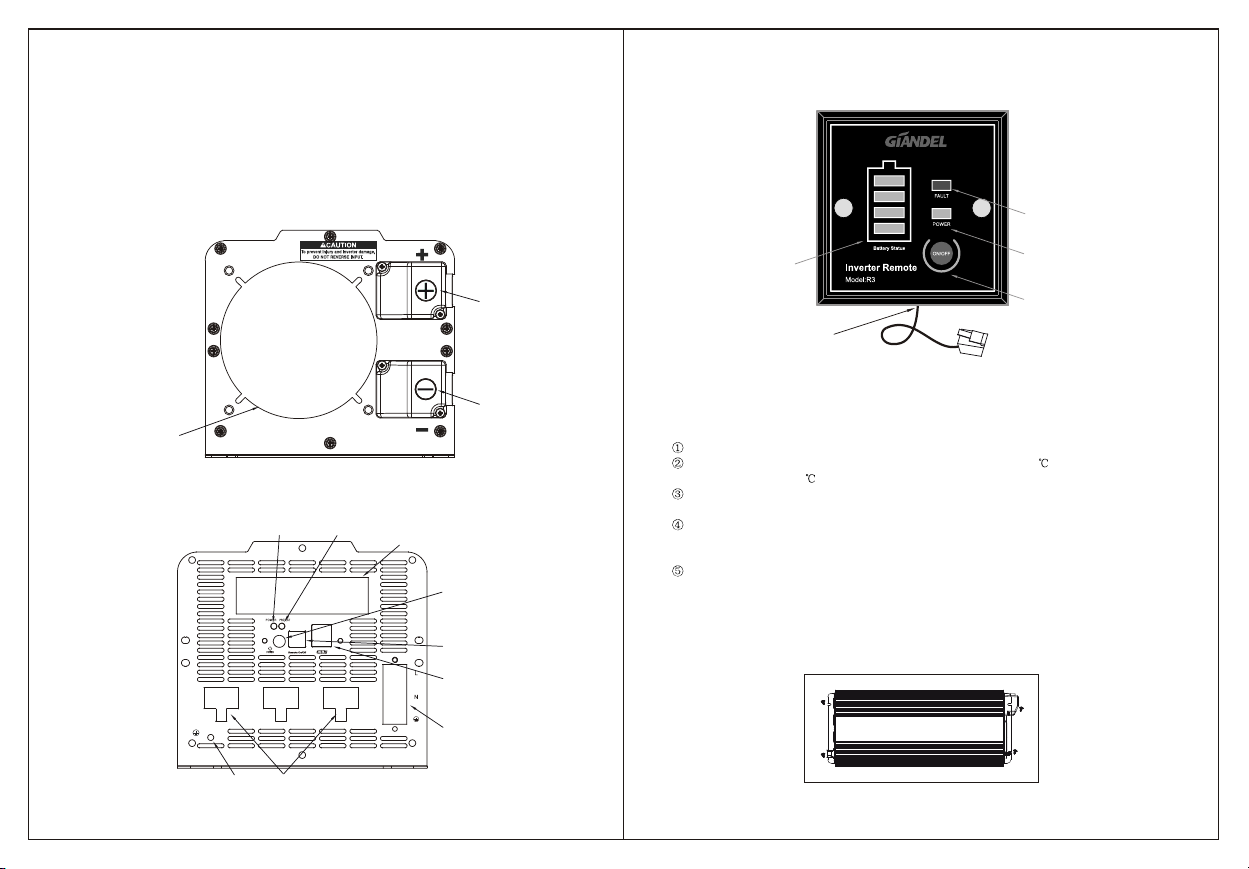
3) Installation of remote control box
Fixed on the plane with anopening, then fix two screws directlyon the position of two
installation holes of the remote control box.
The remote control box can alsobe installed on the base of 86X86mmelectrical socket.
Connect the connection between the remotecontrol box and the inverter.
Note: This product can also be usedas a common inverter without connecting theremote
control box.
Battery Status
FAULT
POWER
ON/OFF
Inverter Remote
Model:R3
85mm
4.5mm
5. BATTERY
1) Current and voltage of batteryThe battery is used to supplythe DC input voltage
required by the product, and itsrated voltage must be in line with the rated input
voltage of the inverter, beyondthe input voltage range of the inverter, and the cross
connection will cause the product tobe under voltage or under voltage protection.
At the same time, the battery mustprovide enough current for inverter,a small capacity
battery is not able to drive highpower appliances, in this case, usually dueto excessive
current and battery discharge the batteryterminal voltage low, under voltage protection
products appear
The simple formula for the batterycurrent is the load power / the battery voltage. As the
inverter itself will be part ofthe loss, so the actual current will be greater than this value
of about 10%. For example: thebattery voltage is 12VDC, the load power is 1000W,
then the actual current size ofthe battery is about 1000W 12V 110%=91.6A
2) Battery working time
The using time of battery dependson battery capacity (AH) and the power of the
connected load (W), the calculating methodis: Time (hours) =battery capacity (AH) x
battery output voltage (V) x efficiencyrate electrical power of using (W) suchas the
12V DC input inverter uses the12V battery, if thebattery capacity is 2000AH and at
this time the inverter is driving1000W power load, the efficiency rateis 90% when the
battery is full, according to theformula above, the battery use time =2000(AH) / (1000 /
12x110%) = 21.8 (Hour).This means the battery can be used for 21.8 hours.
Note: The above formula is the calculationresult of the battery discharging rate in 20
hours, that is, when the discharging currentof 2000 Ah battery doesnot exceed 100A,
the discharging time will be shortenedwhen the discharging current exceeds this value.
This part can refer to thebattery manufacturer's specifications, and whether the battery
is fully charged will also affectthis result.
6. CONNECTION
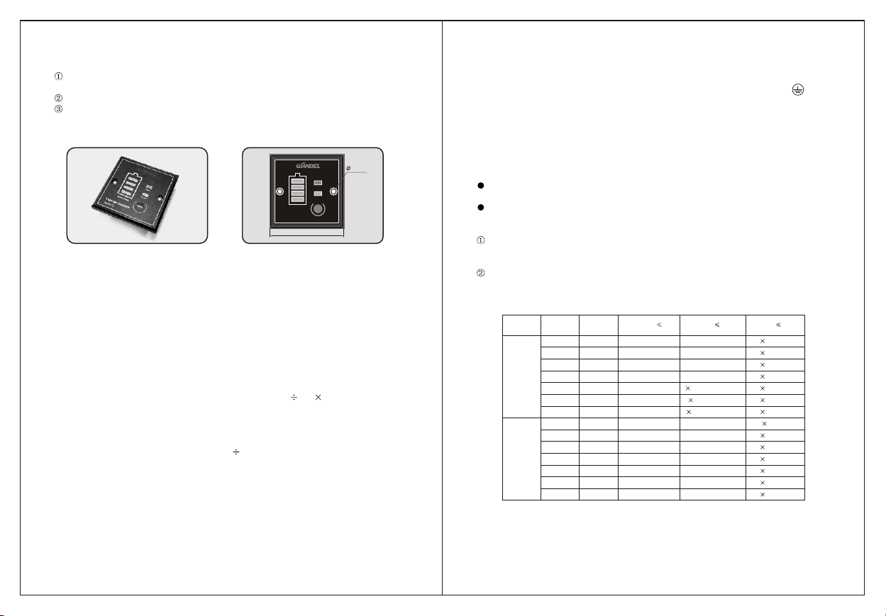
1) Grounding
The power inverter has a terminal onthe back panel marked "Grounding" or " ".
This is used to connect thechassis of the power inverter to the ground.
The ground terminal has already connectedto the ground wire ofAC output receptacle
through the internal connecting wire. Theground terminal must be connected to the
ground wire, which will vary depending onwhere the power inverter is installed. In a
vehicle, connect the ground terminal to thechassis of the vehicle. On the ship, connect
the ground terminal to the shipgrounding system; In a fixed position, connect the
ground terminal to the earth.
Warnings:
To makesure the firmness of the connection. The ground wire must be 14AWG (
2
2.08mm ) or even larger.
Do not operate the power inverter withoutconnecting to ground. Electric shock hazard
may result.
2) Connect to the battery
Please do all the safety precautions beforeconnection, then check whether the battery
voltage is in accordance with theinput voltage of the inverter. Only the voltage of
battery according with the requirements canbe allowed to connect with the inverter.
The connecting wire must be bigenough to bear current, or else the inverter can not
support big load because of voltagereduce caused by the small cross-sectional wire.
Depending on the below table, pleaseselect the input DC wire or larger one.
Inverter Input
voltage Rated power Max current
of cable
Specification of
wire length 1m
(Cross section area)
12V
24V
1000W
1500W
2000W
2500W
3000W
4000W
5000W
1000W
1500W
2000W
2500W
3000W
4000W
5000W
100A
150A
200A
250A
300A
400A
500A
50A
75A
100A
125A
150A
200A
250A
2
6AWG(13.30mm)
2
4AWG(21.15mm)
2
3AWG(26.67mm)
2
2AWG(33.62mm)
2
1AWG(42.41mm)
2
0AWG(53.49mm)
2
00AWG(67.43mm)
2
9AWG(6.63mm)
2
7AWG(10.55mm)
2
6AWG(13.3 mm)
2
5AWG(16.77mm)
2
4AWG (21.15mm)
2
3AWG (26.67mm)
2
2AWG (33.62mm)
2
N 13.30mm
2
N 21.15mm
2
N 26.67mm
2
N 33.62mm
2
N 42.41mm
2
N 53.49mm
2
N 67.43mm
2
N 6.63mm
2
N 10.55mm
2
N 13.30mm
2
N 16.77mm
2
N 21.15mm
2
N 26.67mm
2
N 33.62mm
Specification of wire
length 1m
(Cross section area)
Specification of wire
length N m
(Cross section area)
2
3AWG(26.67mm )
2
1AWG(42.41mm )
2
0AWG(53.49mm )
2
00AWG(67.43mm )
2
2 1AWG(84.82mm )
2
2 0AWG(107mm )
2
2 00AWG(135mm )
2
6AWG(13.3mm )
2
4AWG(21.15mm )
2
3AWG(26.67mm )
2
2AWG(33.62mm )
2
1AWG(42.41mm )
2
0AWG(53.49mm )
2
00AWG(67.43mm )
Notice:
1. The above table is onlyfor your reference. In practice, the thick wire can be replaced by
two thin parallel wires if onlythe total section acreage of thewire meets the
requirements.
Power Inverter With
Remote Controller