Gigaset Pro N720 DECT IP Technical manual

N720DECT IP
Site Planning and Measurement Guide
Multicell System


1
Table of Contents
Table of Contents
Safety precautions . . . . . . . . . . . . . . . . . . . . . . . . . . . . . . . . . . . . . . . . . . . . . . . . . 2
Introduction . . . . . . . . . . . . . . . . . . . . . . . . . . . . . . . . . . . . . . . . . . . . . . . . . . . . . . . 3
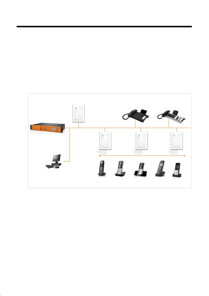
The Gigaset N720 DECT IP Multicell System . . . . . . . . . . . . . . . . . . . . . . . . . . . . . . . . . . . . 3
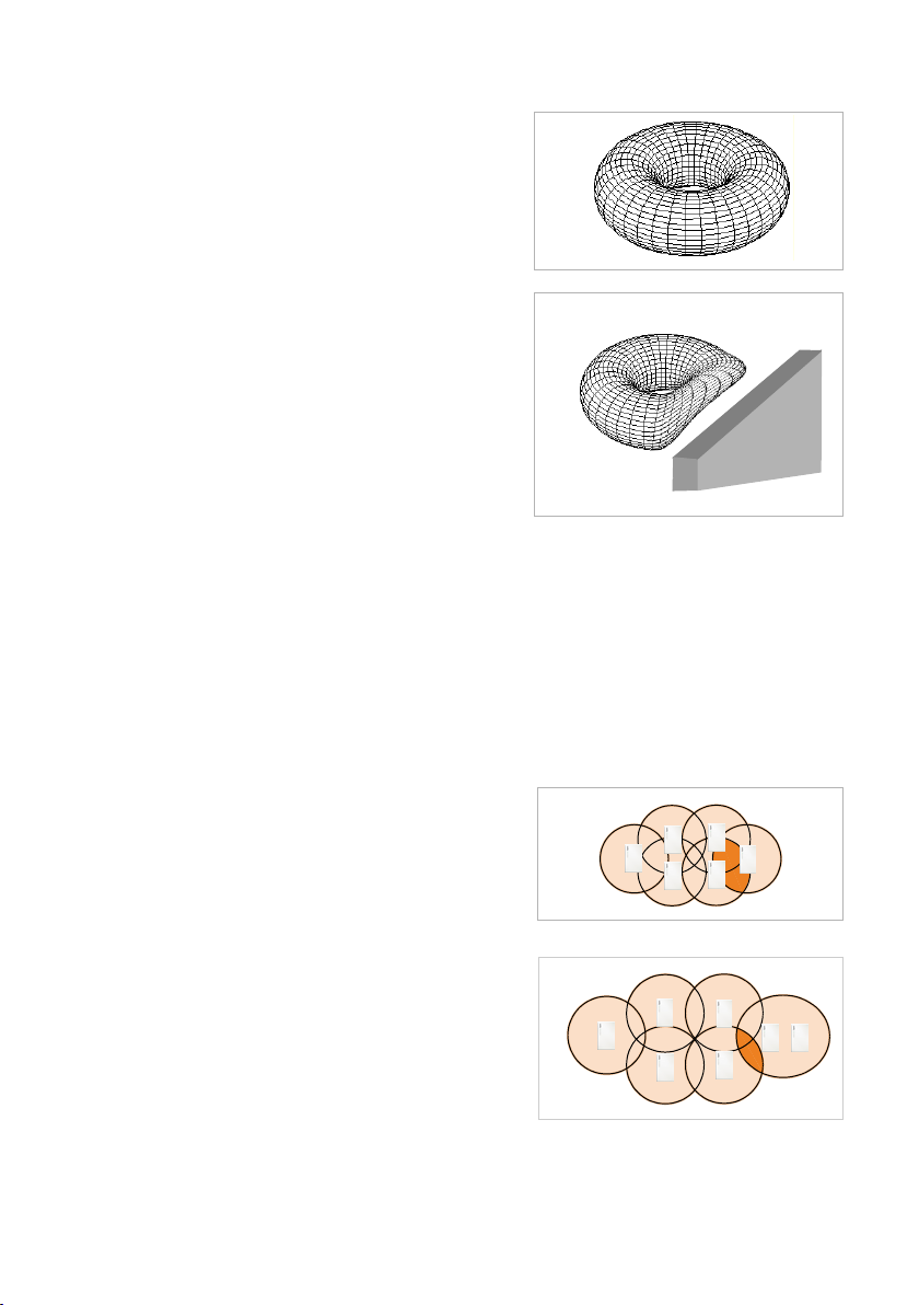
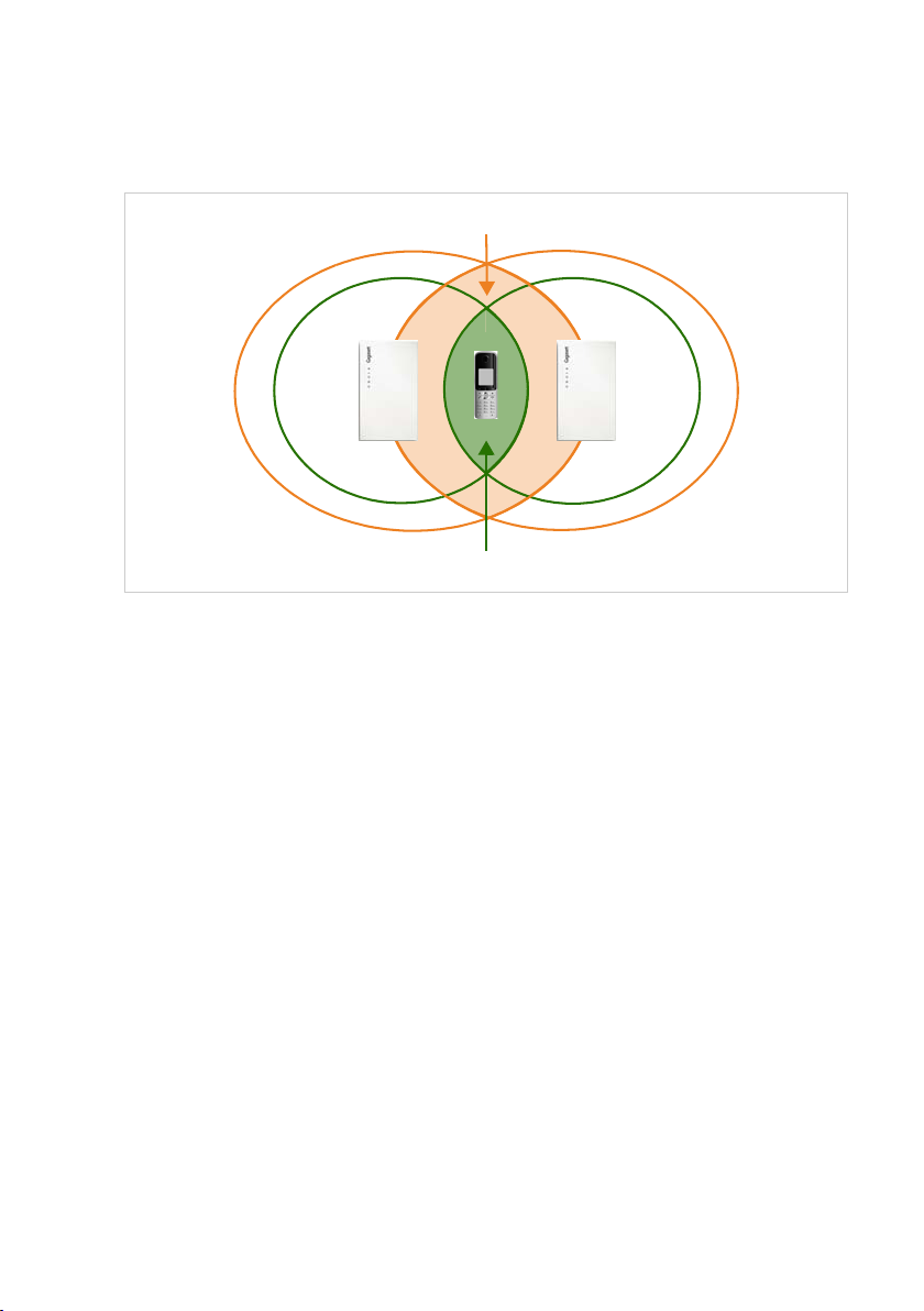
Criteria for an optimum DECT wireless network . . . . . . . . . . . . . . . . . . . . . . . . . . . . . . . . 5
How to proceed . . . . . . . . . . . . . . . . . . . . . . . . . . . . . . . . . . . . . . . . . . . . . . . . . . . . . . . . . . . . . . 8
Projecting the DECT network . . . . . . . . . . . . . . . . . . . . . . . . . . . . . . . . . . . . . . . 9
Determining the requirements for the telephone network . . . . . . . . . . . . . . . . . . . . . 9
Conditions for the positioning of the base stations . . . . . . . . . . . . . . . . . . . . . . . . . . . . 10
Preliminary identification of the positions of the base stations . . . . . . . . . . . . . . . . . 18
Taking measurements . . . . . . . . . . . . . . . . . . . . . . . . . . . . . . . . . . . . . . . . . . . 20
Defining limit values . . . . . . . . . . . . . . . . . . . . . . . . . . . . . . . . . . . . . . . . . . . . . . . . . . . . . . . . . 21
Measuring the wireless range of the planned base stations . . . . . . . . . . . . . . . . . . . . 24
Evaluating measurements . . . . . . . . . . . . . . . . . . . . . . . . . . . . . . . . . . . . . . . . . . . . . . . . . . . . 28
Working with the Gigaset N720 SPK PRO . . . . . . . . . . . . . . . . . . . . . . . . . . 29
Checking the package contents . . . . . . . . . . . . . . . . . . . . . . . . . . . . . . . . . . . . . . . . . . . . . . 29
Further recommended accessories . . . . . . . . . . . . . . . . . . . . . . . . . . . . . . . . . . . . . . . . . . . 30
Before you begin . . . . . . . . . . . . . . . . . . . . . . . . . . . . . . . . . . . . . . . . . . . . . . . . . . . . . . . . . . . . 31
Setting up the measuring base station . . . . . . . . . . . . . . . . . . . . . . . . . . . . . . . . . . . . . . . . 31
Starting up the measuring handset . . . . . . . . . . . . . . . . . . . . . . . . . . . . . . . . . . . . . . . . . . . 35
Operating the measuring handset . . . . . . . . . . . . . . . . . . . . . . . . . . . . . . . . . . . . . . . . . . . . 37
DECT installations in special environments . . . . . . . . . . . . . . . . . . . . . . . . 41
Customer care and help . . . . . . . . . . . . . . . . . . . . . . . . . . . . . . . . . . . . . . . . . . 43
Questions and answers . . . . . . . . . . . . . . . . . . . . . . . . . . . . . . . . . . . . . . . . . . . . . . . . . . . . . . 43
Environment . . . . . . . . . . . . . . . . . . . . . . . . . . . . . . . . . . . . . . . . . . . . . . . . . . . . 43
Our environmental mission statement . . . . . . . . . . . . . . . . . . . . . . . . . . . . . . . . . . . . . . . . 43
Environmental management system . . . . . . . . . . . . . . . . . . . . . . . . . . . . . . . . . . . . . . . . . 43
Disposal . . . . . . . . . . . . . . . . . . . . . . . . . . . . . . . . . . . . . . . . . . . . . . . . . . . . . . . . . . . . . . . . . . . . . 43
Appendix . . . . . . . . . . . . . . . . . . . . . . . . . . . . . . . . . . . . . . . . . . . . . . . . . . . . . . . 44
Care . . . . . . . . . . . . . . . . . . . . . . . . . . . . . . . . . . . . . . . . . . . . . . . . . . . . . . . . . . . . . . . . . . . . . . . . . 44
Contact with liquid . . . . . . . . . . . . . . . . . . . . . . . . . . . . . . . . . . . . . . . . . . . . . . . . . . . . . . . . . . 44
Authorisation . . . . . . . . . . . . . . . . . . . . . . . . . . . . . . . . . . . . . . . . . . . . . . . . . . . . . . . . . . . . . . . . 44
Specifications . . . . . . . . . . . . . . . . . . . . . . . . . . . . . . . . . . . . . . . . . . . . . . . . . . . . . . . . . . . . . . . . 45
Accessories . . . . . . . . . . . . . . . . . . . . . . . . . . . . . . . . . . . . . . . . . . . . . . . . . . . . . . 46
Glossary . . . . . . . . . . . . . . . . . . . . . . . . . . . . . . . . . . . . . . . . . . . . . . . . . . . . . . . . 47
Index . . . . . . . . . . . . . . . . . . . . . . . . . . . . . . . . . . . . . . . . . . . . . . . . . . . . . . . . . . . 51

2
Safety precautions
Safety precautions
Warning
Read the safety precautions and the user guide before use.
Use only the power adapter supplied.
Use only the recommended, rechargeable batteries (£page 45) as this could
otherwise result in significant health risks and personal injury.
Using your telephone may affect nearby medical equipment. Be aware of the
technical conditions in your specific location e.g., doctor's surgery.
Do not hold the rear of the handset to your ear when it is ringing or when
speaker mode is activated, otherwise you risk serious and permanent damage
to your hearing.
Your Gigaset is compatible with the majority of digital hearing aids on the mar-
ket. However, perfect function with all hearing aids cannot be guaranteed.
The handset may cause an unpleasant humming or whistling noise in hearing
aids or cause them to overload. If you require assistance, please contact the
hearing aid supplier.
Do not install the base station and charger in bathrooms or shower rooms.
The base station is not splashproof.
Do not use the devices in environments with a potential explosion hazard, for
example, paint shops.
If you give your phone to a third party, make sure you also give them the
user guide.
Remove faulty devices from use or have them repaired by our Service team, as
these could interfere with other wireless services.

3
Introduction
Introduction
This document explains the preparations necessary to install a multi-cell DECT network
and take measurements for the optimum positioning of the base stations. It also provides
technical and practical background information.
The Gigaset N720 DECT IP Multicell System
The Gigaset N720 DECT IP Multicell System is a DECT multi-cell system for connecting
DECT base stations to a VoIP PABX. It combines the options of IP telephony with the use
of DECT telephones.
The following illustration shows the components of the Gigaset N720 DECT IP Multicell
System and how they are embedded in the IP telephone environment:
uDECT Manager Gigaset N720 DM PRO
Central management station for managing the DECT network. One DECT Manager
must be used for each installation.
– Manages up to 20 DECT base stations
– Manages up to 100 handsets on multi-cell systems
– Enables division into subnets (Cluster formation)
–Forms the interface to an IP PABX (e.g., Gigaset T500 PRO or Gigaset T300 PRO)
A Web user interface is available for configuring and administering the DECT network.
uGigaset N720 IP PRO DECT base stations
– These are the cells of the DECT telephone network.
– Each base station can manage up to eight calls simultaneously (see the Capacity
section £page 6)
PABX
VoIP, ISDN, analogue
DECT
base stations
Gigaset N720
IP PRO
DECT Manager
Gigaset N720 DM PRO
LAN
Configuration via
Web interface
Handover & roaming
Gigaset IP PRO telephones
e.g., Gigaset DE900 IP PRO
Gigaset
handsets

4
Introduction
uGigaset handsets
– Up to 100 handsets can be connected and up to 30 calls conducted simultaneously.
The following handsets are recommended: Gigaset SL610H, SL400H, S810H, E49H.
– Subscribers can accept or initiate calls in all DECT cells with their handset (Roam-
ing), and can also switch between the DECT cells during a call (Handover).
uPABX
You can connect your DECT telephone system to a PABX for VoIP, ISDN or analogue
telephony, e.g., a Gigaset T500 PRO.
– Establishes the connection to a public telephone network for analogue, VoIP or
ISDN calls.
– Enables central management of telephone connections, directories, network mail-
boxes, etc.
uCluster formation with Gigaset N720 DECT IP Multicell System
You can divide DECT base stations that you have installed at your location into several
independent groups, i.e., clusters, and manage them using one Gigaset N720 DM PRO
DECT Manager.
The DECT Manager is connected to the base stations and the PABX via the local net-
work and is therefore not dependent on DECT ranges. This means that you can install
separate DECT islands at your location but manage them centrally, i.e., they have
access to the centrally configured IP connections, directories, etc.
For further information about the options provided by the Gigaset N720 DECT IP Multicell
System, and about installing, configuring and operating the Gigaset devices mentioned,
see the relevant user guide. These are provided on the product CD or on the Internet at
www.gigaset.com/pro.
Gigaset offers the Gigaset N720 SPK PRO (Site Planning Kit) to help you with measuring
the wireless coverage and quality of your DECT network. For information on setting up
and using the Gigaset measuring equipment, see the Working with the Gigaset N720
SPK PRO chapter £page 29.
LAN
DECT
Manager
Cluster 1 Cluster 2

5
Introduction
Criteria for an optimum DECT wireless network
A carefully planned DECT wireless network with adequate coverage is the prerequisite for
operating a telephone system that offers good call quality and sufficient call options for
all subscribers in all buildings and areas belonging to the PABX.
It is difficult to assess the technical wireless conditions of a DECT installation in advance
as they are influenced by many environmental factors. Therefore, the specific circum-
stances on-site must be determined by taking measurements. This produces a reliable
statement about the material required as well as the locations of the wireless units.
Various aspects need to be taken into consideration when planning a DECT wireless net-
work. The following requirements must be considered when deciding how many base
stations are required and where they should be placed:
uSufficient DECT wireless coverage of the entire site so that every subscriber can be
reached.
uSufficient wireless channels (DECT bandwidth), in particular in "hotspots", to avoid
capacity bottlenecks.
uSufficient overlap of cells to enable synchronisation of the base stations and to guar-
antee freedom of movement for subscribers when making calls.
Wireless coverage
The selection of locations where the base stations are to be installed should guarantee
optimum wireless coverage and enable cost-effective wiring.
Optimum wireless coverage is achieved if the required reception quality is delivered at all
points of the wireless network. If costs need to be considered, this should be done with a
minimum number of DECT base stations.
To ensure an interference-free switch of call connections from one cell to another (hando-
ver), there must be an area where good reception is ensured for both base stations. To
achieve this, a minimum quality for reception must be defined.
Wireless cell
Base station
Overlap

6
Introduction
Signal transmission
The ideal signal transmission of a base station is
shaped like a ring, i.e., so that the registered
handsets can be the same distance away from
the base station in all directions without the
wireless signal being interrupted.
However, the transmission is influenced by var-
ious environmental conditions. For example,
obstacles such as walls or metal doors can
impede the wireless signals or interfere with
their even transmission.
You should investigate the actual conditions
that the planned wireless network will be sub-
jected to by measuring the signal transmission
of the measuring base station at appropriate
positions.
Capacity
The capacity of the cells must be large enough to guarantee that the subscribers can be
reached in high-density traffic. A cell is at full capacity when the number of connections
required for each base station is larger than the number of possible connections.
A Gigaset N720 IP PRO can manage eight connections simultaneously when operated in
narrowband mode (£Narrowband mode, page 49). In broadband mode, four simulta-
neous connections are possible (£Broadband mode, page 47).
There are two options for increasing the capacity:
uReducing the distance between the base stations.
This means that the cells overlap more, giving
the subscriber access to the base stations of
the neighbouring cells. This results in a more
even wireless quality. However, this can result
in considerable installation costs for an exist-
ing system.
uInstalling parallel base stations.
The cell size remains generally constant but
the number of possible connections increases.
Installing the base stations close to one
another means that the additional assembly
costs are low, but a minimum distance must be
observed between the base stations (£Tech-
nical conditions, page 11).
To keep the costs for the devices and for the
installation and maintenance low, as few base stations as possible should be installed.

7
Introduction
Overlapping and synchronising
For interference-free cooperation in a multi-cell DECT network, the base stations must
synchronise. In order to synchronise the base stations and ensure a smooth handover, the
cells must overlap.
A sufficient number of large overlapping zones between neighbouring cells must be
ensured. To achieve synchronisation, the reception must be of sufficient quality to ensure
that the base stations can receive one another securely. For a handover, a handset must
have a connection of sufficient quality to both base stations. You will find information
about possible interferences in the Defining limit values section £page 21.
The more densely the base stations are installed, the greater the overlap. Here, a compro-
mise must be found between keeping the area relatively open and installing the lowest
possible number of base stations.
Handover overlap
Synchronisation overlap

8
Introduction
How to proceed
Use the following guide to quickly locate the most important topics.
If you have any questions about using your measuring devices, please contact
our Customer care team (£page 43).
Information on ... ... is located here.
Determining the requirements for the telephone network
Determine the requirements for the telephone network and collect
information about the environmental conditions for the planned
DECT wireless network.
page 9
Creating an installation plan
Create a building plan and enter the planned DECT base stations in
this plan. You should take account of the general conditions deter-
mined and the technical requirements of DECT telephony in the
process.
page 18
Taking measurements
Use the installation plan to take measurements and adapt the instal-
lation plan to your measurement results.
page 20
Working with the Gigaset measuring equipment
Have you purchased the Gigaset N720 SPK PRO (Site Planning Kit)?
Here you can read about how to set up the measuring equipment
and how to use it to take measurements.
page 29
Special environments
Do you want to set up your DECT network in a difficult environment?
Helpful information and tips are available here.
page 41
g
g
g
g
g

9
Projecting the DECT network
There are a number of conditions to be considered when setting up a DECT network. They
affect the subscribers' requirements for the telephone system as well as the technical
requirements for the DECT wireless network. These conditions must therefore be
recorded and evaluated in a projection phase.
To project your DECT network, proceed as follows:
uFirst determine the requirements for the telephone network and establish the environ-
mental conditions for the DECT wireless network.
uDefine how many base stations are required and their probable optimum positioning.
Create an installation plan for the base stations.
uTake measurements to check whether the positioning of the base stations at the
assumed positions meets the requirements and whether the reception and sound
quality is sufficient everywhere. If necessary, change the installation plan to optimise
the DECT wireless network.
Determining the requirements for the telephone network
Clarify the following questions to determine the requirements for the telephone network:
Subscribers and subscriber behaviour
uHow many employees should be able to make calls and how many subscribers should
be able to make calls simultaneously?
– How many handsets are required?
– How many base stations are required?
uWhere should telephone calls be possible?
– In which buildings (floors, stairwell, basement, underground garage)?
– Outdoors (on footpaths, on the car park)?
For more information about this, please refer to the information in the section Out-
side area, £page 42.
– How are the handsets distributed from a location perspective?
uHow many calls will be made?
– What is the telephony behaviour of the subscribers? How long is the average call?
– Where are the hotspots, i.e., where do a lot of subscribers gather simultaneously
(open-plan office, canteen, cafeteria, etc.)?
– Where are telephone conferences held? How many telephone conferences are held
and how long are these?
Environmental conditions
uWhere is the site that is to be covered by the DECT wireless network?
– Total area of the required wireless coverage
– Position and dimensions of the rooms, building plan
– Number of floors, basements
¤Request a building plan that shows positions and dimensions and that can be used
to document the subsequent installation planning.

10
Projecting the DECT network
uWhat is the basic structure of the building?
– What materials and construction types have been used for the buildings?
– What type of windows does the building have (e.g., tinted glass)?
– What construction changes are expected in the near future?
uWhat disruptive influences can be identified?
– What are the walls made of (concrete, brick, etc.)?
– Where are the lifts, fire doors, etc. located?
– What furniture and devices are present or planned?
– Are there other wireless sources in the vicinity?
For detailed information on material characteristics and interference factors, £page 16.
Conditions for the positioning of the base stations
Features of the Gigaset N720 DECT IP Multicell System
uA Gigaset N720 DM PRO DECT Manager can manage a maximum of 20 base stations
and 100 handsets.
uThe DECT network can be divided into clusters; i.e., you can install several independent
DECT islands that are managed centrally by a DECT Manager.
uA Gigaset N720 IP PRO base station can establish a maximum of eight connections
simultaneously (four connections in Broadband mode).
This must be taken into consideration in the capacity calculations (£page 13).
Technical conditions
The following values can be used as a guide for the planning. They are values that are
influenced by environmental conditions and that should therefore be checked via meas-
urements.
uThe wireless range of a DECT base station for handsets is (guide values)
– Up to 50 m indoors
– Up to 300 m outdoors
These guide values do not apply to the maximum possible distance between two base
stations. To ensure the handover of a handset from the cell of one base station to the
cell of another, this distance is derived from the necessary overlap zone.
uEnsure adequately sixed overlap zones between neighbouring cells are taken into
consideration. For an interference-free handover, a spatial overlap of 5 to 10 metres
with satisfactory signal strength should be sufficient, even for fast walking. Neighbour-
ing base stations must be able to receive one another with sufficient signal strength to
guarantee the synchronisation and handover (£page 21).

11
Projecting the DECT network
uMaintain sufficient distance between the base stations as they can interfere with one
another. The minimum distance depends on the circumstances. If no obstacles are
present, the required distance can be 5 to 10 metres. If there is an absorbent wall or
absorbent furniture between the base stations, 1 to 2 metres may be sufficient. You
will also find information about possible interferences in the Material characteristics
and interference factors section £page 16.
uIn a horizontal direction, good connections can still be established behind 2–3 normal
brick walls. In a vertical direction and on the ground floor or in basements, concrete
ceilings are difficult to penetrate. This means that every floor may have to be supplied
separately.
uPlease note that in empty buildings, adding furniture and equipment (machines, mov-
able walls, etc.) at a later stage will affect the wireless quality.
uOpenings in obstacles improve the technical wireless conditions.
uConsider any possible interference factors (£page 16).
Installation guidelines
The following points must be considered when installing DECT base stations:
uFor wireless coverage within a building, always install the base stations on internal
walls. Information on installation in an outside area, £page 42.
uDepending on the room height, the optimum installation height of a base station is
between 1.8 and 3 m. If you want to install the base stations at a lower height, interfer-
ence can occur as a result of furniture or movable objects. There should be a minimum
clearance of 0.5 m to the ceiling.
uWe recommend installing all base stations at the same height.
uThe Gigaset N720 IP PRO base stations require an Ethernet connection to the PABX, i.e.,
it must be possible to connect to the LAN.
uThe Gigaset N720 IP PRO base stations are powered by PoE (Power over Ethernet,
IEEE 802.3af). Therefore, you do not normally require a power connection. However, if
you use an Ethernet switch that does not support PoE, you can use a PoE injector as an
alternative. If there is an option of connecting to the mains power supply in the vicinity
of the base station, you can also use the power adapter to provide a power supply (to
be ordered separately).
uDo not install the base station in suspended ceilings, cupboards or other closed fur-
nishings. The wireless coverage can be significantly reduced, depending on the mate-
rials used.
uThe base station should be installed vertically.
uThe location and alignment of the base station installed should be identical to the
position deemed optimum during the measurement stage.
uAvoid installation in the direct vicinity of cable channels, metal cupboards or other
larger metal parts. These can reduce the radiation and couple into interfering signals.
There should be a minimum distance of 50 cm.
uObserve the safety distances and safety regulations. Observe the regulations specified
in rooms where there is a danger of explosions.

12
Projecting the DECT network
Synchronisation planning
Base stations that combine to form a DECT wireless network must synchronise with one
another to ensure a smooth transition of the handsets from cell to cell (handover). No
handover is possible between cells that are not synchronised.
They are synchronised via what is known as an air interface, i.e. via the DECT wireless net-
work. This means that the signal strength between neighbouring base stations must be
sufficient for synchronisation. The guide value is a minimum of –70 dBm, but this can also
be influenced by environmental conditions. For further information on this, please also
refer to the Defining limit values section £page 21.
The synchronisation takes place in a master/slave procedure. This means that one base
station (master) defines the synchronisation cycle for one or more other base stations
(slaves). Since it is generally the case that not all base stations have a good enough con-
nection to all other base stations in a multi-cell DECT network, it is not possible to have
only one master station and to configure all others as slaves. Instead, you have to set up a
synchronisation hierarchy. You can configure this hierarchy using the Web user interface
of the Gigaset N720 DM PRO DECT Manager.
During configuration, assign one level in the synchronisation hierarchy (sync level) to
each base station. Sync level 1 is the highest level; it appears only once in each cluster.
A base station always synchronises itself with a base station that has a better sync level. If
it sees several base stations with a better sync level, it synchronises itself with the base sta-
tion that has the strongest signal. If it does not see any base station with a higher sync
level, it cannot synchronise. A Gigaset N720 IP PRO base station shows its synchronisation
status with an LED.
For information on synchronising base stations, please refer to the user guide for the
Gigaset N720 IP PRO and Gigaset N720 DM PRO.
Please note
Synchronisation always refers to a cluster. You can set up several clusters that are not
synchronised with one another, so there is no possibility of a handover between clus-
ters.
Please note
We recommend giving the base stations a name during planning and entering the
name in the plan. The name should define the unique location in the building. It is also
helpful to document the assignment of the names to the MAC addresses of the
devices.
This makes the configuration of the synchronisation hierarchy in the Web user inter-
face and the assignment to the installed devices easier later on.

13
Projecting the DECT network
Depending on the topology of your DECT network, your synchronisation hierarchy could
look like this, for example.
Capacity measurement
The capacity of the PABX must be large enough to guarantee that the subscribers can be
reached in high-density traffic. Both the capacity of the entire PABX and the capacity of
the individual cells must be taken into account.
The capacity of the PABX is determined using the following criteria:
uNumber of connection channels available
The number of connection channels available defines how many calls can be con-
ducted simultaneously. Reminder: the number of possible connections per base sta-
tion is eight in Narrowband mode, four in Broadband mode.
uGrade of service (GoS)
The grade of service determines the number of connections that may not be achieved
due to the system being at full capacity, i.e., the line is engaged. A grade of service of
1% means that out of 100 calls, one cannot be connected for capacity reasons.
The capacity required can be determined using these two factors and the traffic volume
expected.
Please note that the volume of traffic can vary during the course of the day.
During the synchronisation planning, make
sure that the distance to the base station
with sync level 1 is as short as possible from
all sides, i.e., that there are as few levels as
possible. It makes sense to select the station
that is at the centre of your DECT network as
the base station with sync level 1.
3 2 321
54321
Correct:
Incorrect:
5 4 3
5432
543
13
2
22
2
3
33
33
3
3
4
44
4
44
4
2
1
5432
2
1
1
2
22
2
3
33
3

14
Projecting the DECT network
The capacity must always be adjusted to the highest possible traffic volume if
capacity bottlenecks are to be excluded.
Traffic volume
The traffic volume is expressed in "erlangs (E)". One erlang corresponds to the continuous
full capacity utilisation of one connection channel in a specific period. Erlangs are usually
calculated over an observation period of one hour. Accordingly, the occupation of a con-
nection channel over one hour equals one erlang.
For example: if all eight connections of a base station are continuously occupied, this corre-
sponds to eight E. If a connection is occupied for 20 minutes, this corresponds to 1/3 E.
Examples:
Let us assume that 500 calls lasting 3 minutes each are made within one hour.
500 x 3 min/60 min = 25 E
Therefore, at least25 connection channels, i.e., four base stations (in Narrowband mode),
would be necessary for this call volume.
However, this only applies if the grade of service is less than 4%. With a grade of service
of 4%, you need only three base stations, i.e., 24 connection channels. With a grade of
service of 4%, it is permissible for 20 calls from 500 not to be established. This means that
only 480 connections have to be achieved. The calculation is as follows:
480 x 3 min/60 min = 24 E
Since the traffic volume is not normally evenly distributed over the site to be covered, the
traffic volume must be calculated for each area (offices, reception, hotspots, stairwell, etc.)
in order to determine the relevant number of base stations that need to be installed.
Grade of
service
Calls at 3 min. per hour The table contains some
sample values for the calcula-
tion of the traffic volume
depending on the grade of
service, call duration and
number of calls per hour.
Using the data you have
determined about the
telephony behaviour, you
can realistically estimate
your requirements.
10 50 100 500
0 % 0.5 E 2.5 E 5 E 25 E
2 % 0.49 E 2.45 E 4.9 E 24.5 E
4 % 0.48 E 2.4 E 4.8 E 24 E
Grade of
service
Calls at 15 min. per hour
10 50 100 500
0% 2.5 E 12.5 E 25 E 125 E
2% 2.45 E 12.25 E 24.5 E 122.5 E
4% 2.4 E 12 E 24 E 120 E

15
Projecting the DECT network
Alternative calculation for small systems
For smaller systems, an approximate evaluation of the traffic volume can be sufficient.
Examples:
The traffic volume is evaluated for every area as "low", "medium" or "high". The evaluation
specifies the number of handsets that can conduct calls simultaneously as a percentage:
Hotspots
A hotspot is an area in which more calls than average are conducted simultaneously, e.g.,
open-plan offices or other areas where there are a lot of handsets in a small space.
You can cover such areas with several base stations since the DECT bandwidths in the cov-
erage areas of neighbouring base stations add up. The DECT standard provides 120 radio
channels that can be shared by several base stations. In practice, however, approximately
only one quarter of these radio channels can be used without special measures, since the
neighbouring channels interfere with one another. This results in a practical value of a
maximum of 30 simultaneous connections. With a maximum of eight handsets per base
station, this means that four Gigaset N720 IP PRO base stations would be required.
If we assume that a maximum of 50% of the available handsets are making a call simulta-
neously in a hotspot, 60 handsets can be used with four base stations.
If interference frequently occurs at a hotspot or more than 30 connections are required
simultaneously, the following measures are possible:
uDistribute the base stations that cover the hotspot as widely as possible at the bound-
aries of the hotspot so that they are as far away from each other as possible and mutual
interference is minimised.
uIf this measure is not sufficient, use walls or other suitable means to diminish the
strong signals.
uIt might also be helpful, if the circumstances at the location allow, to arrange the base
stations in the shape of a ball, i.e., cover the hotspot through floors and ceilings.
When optimising the coverage of the hotspot areas, make sure that handsets do not sud-
denly occupy the call channels of the hotspot base stations that were previously supplied
by other base stations. When establishing a connection, handsets always occupy chan-
nels of the base station that provides the strongest signal. Therefore, moving the hotspot
base stations may affect other base stations and you may have to relocate the base sta-
tions of the entire network.
Evaluation % Maximum number of handsets that can be
operated from one base station
Low Approx. 10% 80
Medium Approx. 25% 32
High Approx. 50% 16

16
Projecting the DECT network
Material characteristics and interference factors
There are a number of interference factors that influence the range and quality of the
transmission in particular. The types of interference factors include:
uInterference as a result of obstacles that diminish the signal transmission, creating
radio shadows
uInterference through reflection that restricts the call quality (e.g., crackling or back-
ground noise)
uInterference through other radio signals that can lead to errors in transmission
Interference through obstacles
Possible obstacles are:
uBuilding constructions and installations such as reinforced concrete ceilings and walls,
stairwells, long corridors with fire doors, uptakes and cable channels.
uMetal-clad rooms and objects such as cold stores, computer rooms, metallised glass
areas (reflections), firewalls, tank systems, refrigerators, electrical boilers etc.
uMovable metal objects such as lifts, cranes, carts, escalators, shutters
uRoom furnishings such as metal shelves, filing cabinets
uElectronic devices.
It is often difficult to locate the exact source of the interference; particularly if the recep-
tion power of the local DECT signals fluctuates strongly within a few centimetres. In these
cases, the interference can be reduced or corrected by small changes to the position.
Loss of range through building materials in comparison to a free wireless
field:
Please note
Wireless coverage in lifts is normally poor or not available at all (£page 41).
Glass, wood, untreated Approx. 10%
Wood, treated Approx. 25%
Plasterboard Approx. 27 – 41%
Brick wall, 10 to 12 cm Approx. 44%
Brick wall, 24 cm Approx. 60%
Aerated concrete wall Approx. 78%
Wired glass wall Approx. 84%
Reinforced concrete ceiling Approx. 75 – 87%
Metal-coated glass Approx. 100%

17
Projecting the DECT network
Interference from other cells and networks
DECT is very robust against interference from other wireless networks. For example, co-
existence with WLAN is not a problem. Most other asynchronous DECT single base sta-
tions do not present a problem either.
Problems may occur in special cases, such as an environment where there is a very high
level of DECT usage. This applies when there are co-existing asynchronous DECT base sta-
tions but, even more so, when base stations have been installed too close together to
cover a hotspot, for example.
Despite sufficient signal strength, the following interference can occur:
uUnexpected termination of the connection
uLoss of synchronisation of handsets
uPoor voice quality
¤When interference occurs because base stations are installed too closely together, try
to resolve the problem with the measures described in the Hotspots section (increase
the distances, use obstacles to absorb the interference, £page 15)
¤If you have found other DECT sources, check whether you can switch them off, relocate
them or integrate them in your DECT network.
Summary
Wireless traffic interference can have many causes that cannot all be determined in
advance, that increase or decrease due to mutual influences and that can change during
operation.
Therefore, the actual influence of interference factors on reception and voice quality can
only be determined by taking measurements. However, the measurements also only pro-
vide an image of the wireless network at the time of measurement. We therefore recom-
mend that when you plan the DECT network areas where interference can be expected,
you err on the side of caution when you interpret the limit values.

18
Projecting the DECT network
Preliminary identification of the positions of the base stations
Now plan the positions of the base stations. Take the following into consideration:
uThe information you have collected regarding the requirements for the telephone net-
work
uYour synchronisation planning
uThe technical conditions for the wireless DECT.
First create a plan in which you then enter the locations of the base stations. You can use
existing building and supply plans, if applicable. For very large buildings, you may be able
to work with partial floor plans and then merge the results of the measurements into the
evaluation.
Creating a planning drawing
Create a planning drawing from the information you have collected in the preliminary
examination of the location. Enter building dimensions, hotspot areas and any sources of
interference already identified.
Examples:
uThe numbers in the rooms reflect the required number of DECT telephones.
uAreas with high-density traffic are marked as hotspots (HS).
uThe walls marked in bold are assumed to have a high absorption effect, or reflections
can be expected.
uThe dotted lines on the two outer walls indicate tinted windows (coated with metal
film).
uThe stairwell should be covered by DECT wireless transmission. There is a lift here.
30 m
50 m
HS
HS
WC/
store
Stairs
Computers
Table of contents
Other Gigaset Conference System manuals