GigaTera RED Series User manual

Copyright © 2019 GigaTera Lighting Inc. All rights reserved. / www.gigateraled.com
RED Series Installation Guide
External Remote Driver
Model : RED1K2, RED1K0, RED600
Document Revision V2.4 - 20190807
01. Electrical work must be performed by a qualified and licensed electrician.
02. Be sure to perform the construction and grounding work in accordance with the technical standards
and instruction manual.
03. Make sure to ground the product and mounting platform properly. Incomplete grounding may cause product
damage, electric shock or fire.
04. Be sure to install the product only after the grounding work installation pole and stand is completed. Otherwise, it may cause
product damage, electric shock, or fire.
05. In order to prevent the danger of electric shock, cut off the main power and confirm that there is no leakage current before installing.
06. Make sure to turn off the power so there is no leakage current when binding the LED fixture.
There is a possibility of LED chip damage due to no-load voltage.
07. If power is supplied without reliable insulation, there is a risk of product damage, electric shock or fire.
08. Insufficient construction may cause accidents such as product damage, poor insulation, flooding smoke, ignition, electric shock or falling.
09. Safety wire must be installed to avoid injury from falling and product damage.
10. Install the power box with the AC cable gland at the bottom. If installed in a direction other than specified,
it may cause product damage, electric shock or fire.
11. Do not pull the product cable or cut it arbitrary. It may cause product damage, poor insulation, flooding, electric shock or fire.
12. Do not apply excessive force to the product cable. It may cause product damage, poor insulation, flooding, electric shock or fire
13.Make sure the cable has enough space to adjust the angle of the LED fixture.

14. After confirming the usable angle range of the LED fixture, install it so that it does not interfere. It may cause deterioration of light, non-lighting, short life, and fire.
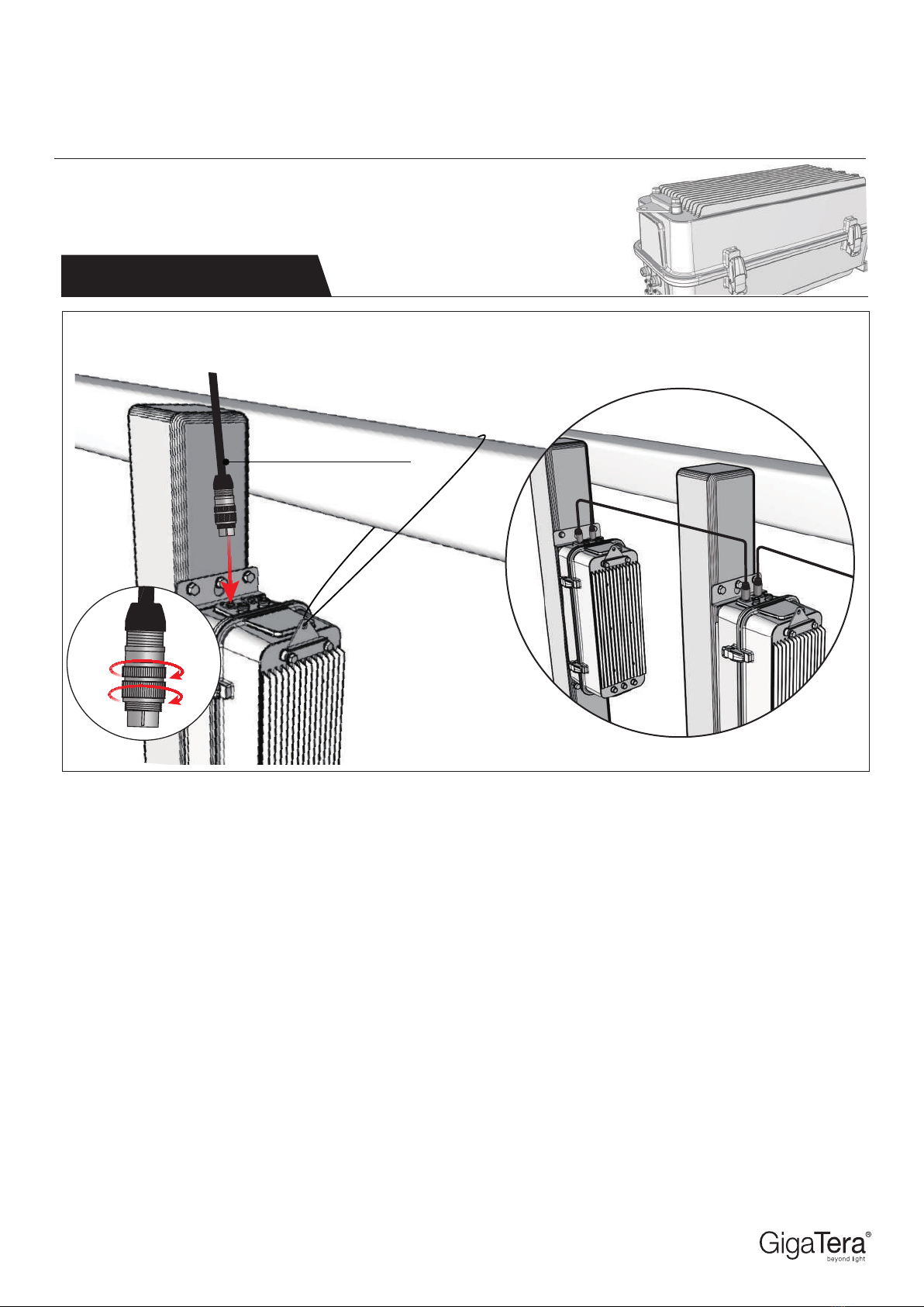
15. Tighten and secure the gland cap of the connection part. Incomplete installation may cause product damage due to flooding, poor insulation, electric shock or fire.
16. Do not leave the power box and LED fixture unconnected (Multiple installation schedule and wiring is prohibited). In case of inevitable connection
of the secondary side during construction, insulate the ends of the wires with insulation tape and self-sealing tape to waterproof it.
If the following steps are not followed, it may cause product damage, poor insulation, immersion, non-lighting, short life, or fire.
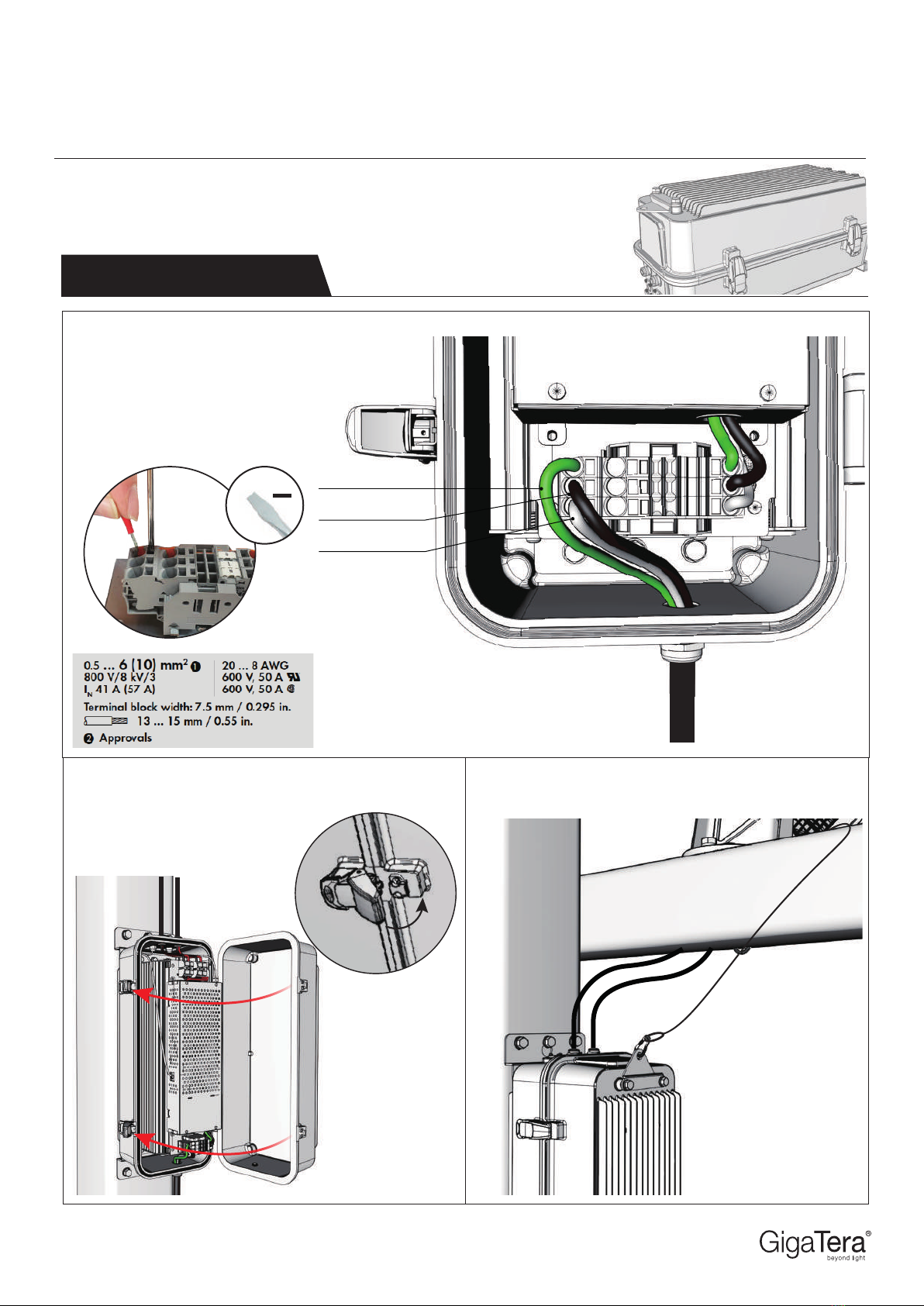
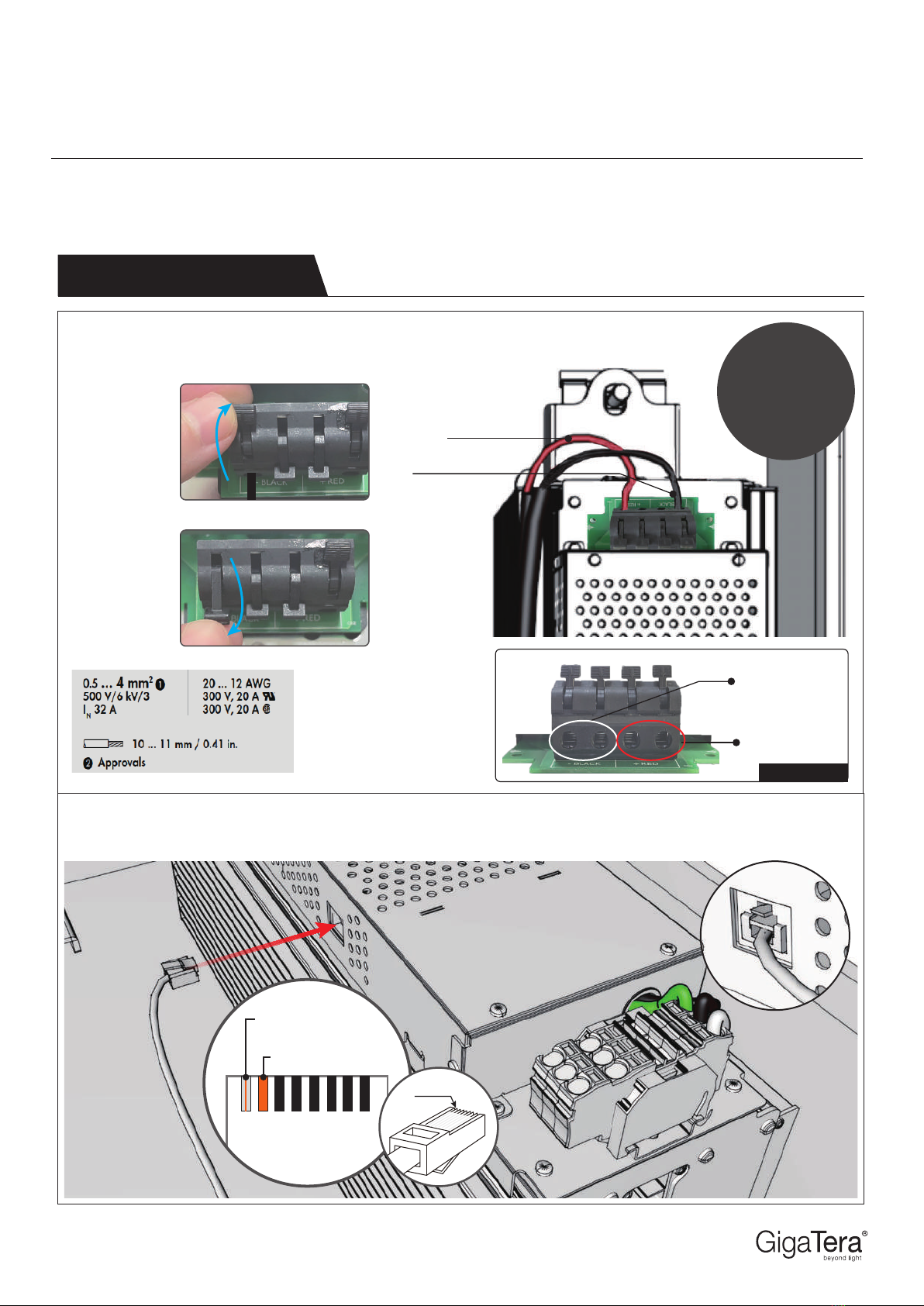
17. The power line must always be connected securely with a sleeve and waterproofed via using insulating tapes and self-sealing tape.
If the power cable is incompletely connected, there is a danger of product damage, electric shock or fire.
18. When bundling wires, separate them one by one without insulating them in bulk, and insulate them with insulating tape and self-sealing tape,
and perform a completely waterproof. Insufficient construction may cause product damage, poor insulation, flooding, electric shock or fire.
19. When wiring, use insulation tape and self-sealing tape from the connection part of the wire to the outer sheath of the wire. Apply over three times
(6 plies) of insulation and complete waterproofing. Insufficient construction may cause product damage, poor insulation, flooding, electric shock or fire.
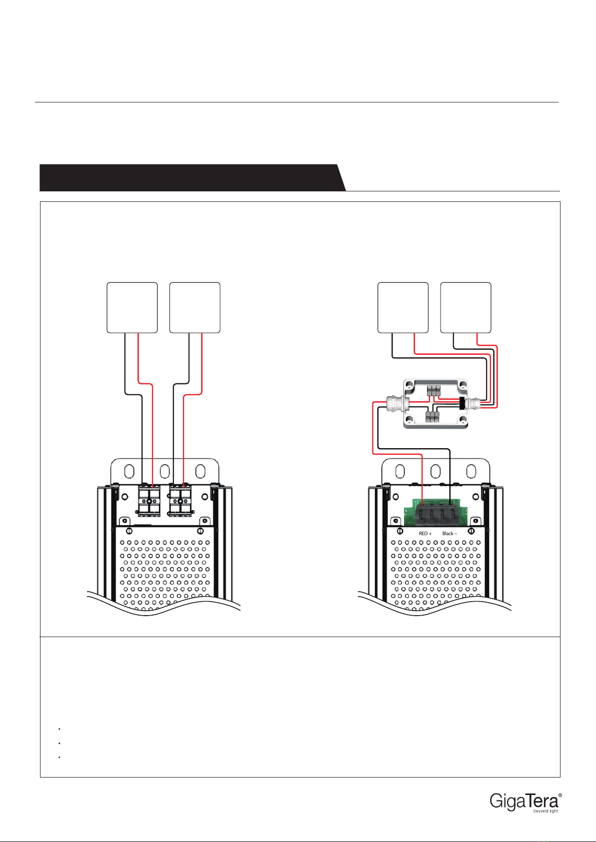
20. When connecting the wires, make sure that there are no misalignment, unconnected wires, or incorrect connections.
If the wiring is incomplete, there is a danger of unlit, uncontrollable, product damage, electric shock or fire.
21. Do not leave the power box open. It may cause product damage, flooding, electric shock or fire.
22. Do not put excessive force to the power box. There is a possibility of product damage, electric shock or fire.
23. When closing the power box, check if there is any damage to ensure that the wires are not pinched. It may cause product damage, flooding, electric shock or fire.
24. Use a high frequency response type earth leakage breaker. If it passes through the breaker, it may cause product damage, electric shock, or fire.
25. When moving and installing the product, please wear safety glove, safety shoes, and other safety equipment to avoid injury.
26. Do not damage the insulator of the wire with a knife or other sharp tools. There is a risk of fire, electric shock or short circuit due to insulation breakdown.
27. Do not scratch the front cover of the product during construction. It may cause damage, poor waterproofing, or reduce illuminance.
If any cracks are found on the front cover, turn off the power immediately and replace it quickly. Contact nearest GigaTera Sales Office for further assistance.
28. Do not cover partially or all parts of the product with any sort of object. Particularly, covering the product may cause deterioration
of illuminance, non-lighting, short life and fire.
29. If the product (especially a heat sink pin) is used in places where there is a risk of falling leaves, dust, and insects, be sure to clean the product regularly.
It may cause deterioration of light, non-lighting, short life, and fire.
30. Use the power within the specified voltage and frequency. It may cause non-lighting, short life, electric shock or fire.
31. Do not use in places with severe vibration or shock, places with corrosive gas, humidity exceeding 85%, salt areas, or places with a lot of dust.
32. Do not install the product in a narrow place or in a place with poor ventilation surrounded by a container. It may cause smoke, ignition,
or severely shortening the life of LEDs and products.
33. Use the product at an ambient temperature of -20 to 35 degrees. When used in a place exceeding the ambient temperature range, the temperature may rise,
which may cause smoke ignition, electric shock, or severely shorten life of the LEDs and the product.
When turning on during the day, please use it only as temporary lighting during construction.
34. When using in a snowfall area, remove the snow regularly during snowfall period. It may cause mechanical damage.
35. Do not use in places where there is a risk of flooding. It may cause short circuit, electric shock or malfunction.
36. Do not store the product in a humid or wet place.
37. When installing two or more products in a row, fix each product at a distance greater than or equal to the width and pay attention to ventilation
Also, be careful not to break or block the gore-tex when installing the power box.
38. This product has a life span. If used in conditions other than those specified, it may cause non-lighting or short life.
39 .Do not look into the LED directly, it may cause eye disorders.
40. LEDs have a greater color uniformity compared to ordinary light sources such as incandescent or fluorescent lamps. Therefore, the color difference of each LED
may be different. In addition, light or color stains may occur due to the irradiation surface.
41. Do not disassemble or modify the product damage, smoke, fire, electric shock or falling.
42. Do not drop or apply strong impact to the product. It may cause product damage.
43. The Manufacturer and dealer are not responsible for any problem caused by consumer negligence.
44. Prior to construction and use, be sure to read the precautions for installation and handling.
45. Please keep this instruction manual.
46. If you notice any abnormality in the product, such as smoke or a strange smell, turn off the power promptly and consult your dealer or construction company.
47. The light source of the illumination cannot be replaced. When the light source and power supply have
reached the end of their service life, the light must be replaced.
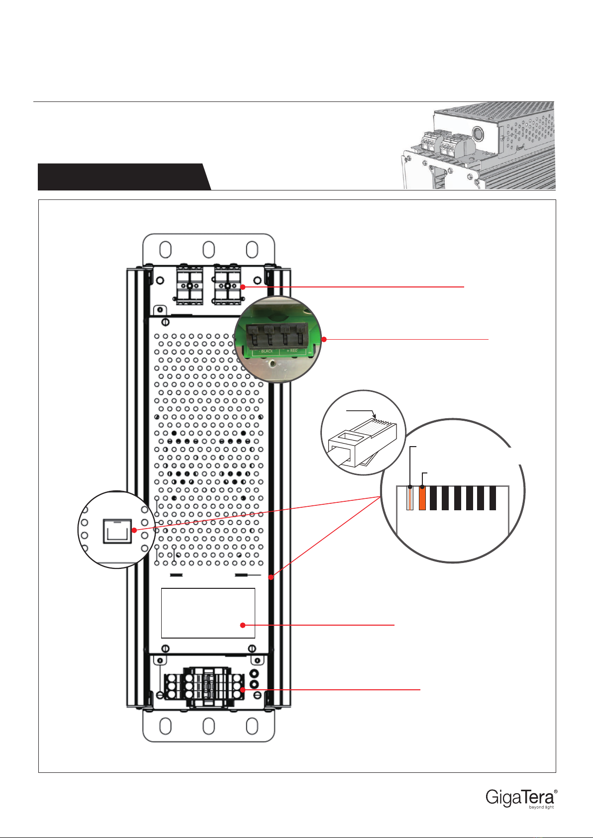
RED Series
External Remote Driver
Model : RED1K2, RED1K0, RED600

< RED1K2, RED1K0 >
Size : 470 x 181.7 x 151.2 (mm)
18.5 x 7.2 x 6.0 (inch)
Weight : 13.0 kg /28.7 lb
IP Rate : IP20
< RED600 >
Size : 470 x 181.7 x 151.2 (mm)
18.5 x 7.2 x 6.0 (inch)
Weight : 10.0 kg / 22.0 lb
IP Rate : IP20
Size : 587 x 245 x 246 (mm)
23.1 x 9.6 x 9.7 (inch)
Weight : 6.5 kg / 16.3 lb
IP Rate : IP66
151.2mm(6.0")470mm(18.5")
181.7mm(7.2")
151.2mm(6.0")470mm(18.5")
181.7mm(7.2")
RED Series Installation Guide
External Remote Driver
Model : RED1K2, RED1K0, RED600
Document Revision V2.4 - 20190807
RED Dimension RED
RED IP BOX Dimension
587mm(23.1") 246mm(9.7")
245mm(9.6")

RED Series Installation Guide
External Remote Driver
Model : RED1K2, RED1K0, RED600
RED Part Name RED1K2
Document Revision V2.4 - 20190807
AC Terminal Block
Product Label
RJ45
DC Terminal BlockType 01.
Type 02. DC Bridge Type
Pin.1
Pin.8
White/
Orange Stripe (TX
+
)
Orange (TX
-
)
Pin.1

[Junction Box]x
< RED - Connector Type >
[ NOTE ]
1) Rated wattage is the power consumption including driver eciency losses, at 25° C stabilized operation in ambient temperature.
2) Operating current includes allowance for 0.90 minimum power factor, operating temperature and and LED light source tolerances.
3) Use thermal magnetic suitable D-curve circuit breakers.
RED Series Installation Guide
External Remote Driver
Model : RED1K2, RED1K0, RED600
Guideline for Wiring & Power Consumption
< RED - Bridge Type >
Document Revision V2.4 - 20190807
DC drop per 10 meter DC Cable from 1.2kW driver to LED module shall be 6.5W based on 2.5mm2DC cable wire thickness.
Recommended core wire thickness from Driver to LED module for DC cable length upto70m : 2.5mm2
Recommended core wire thickness for AC cable from DB to 1.2kW Driver : 2.0 mm2
LED
Module 1
LED1
-
LED1+
LED
Module 2
LED2
-
LED2+
RED + Black
-
LED
Module 1
LED1
-
LED1+
LED
Module 2
LED2
-
LED2+
LED1
-
LED1+ LED2
-
LED2+

STEP 01 : Secure the IP Box on to the pole with
the bolts.
STEP 02 : Open the case cover of the IP BOX.
RED Series Installation Guide
External Remote Driver
Model : RED1K2, RED1K0, RED600
Installation Instruction RED IP BOX (1/3)
STEP 03 : Assemble DC cable. Each cable color have to match. (Red + / Black - )
Push-in termination
If the cross section of the wire is thick or hard, insert
it directly without using tools. For wires that can not
be pushed in due to the small cross section of the
wires, use a at head screwdriver as shown in above.
Document Revision V2.4 - 20190807
DC+ (Red)
DC
-
(Black)
DC+ (Red)
DC
-
(Black)
①
②
RED1K2
RED600
* DC Terminal Block

STEP 04 : Assemble the AC Cable on the
Remote Driver. Please match the cable colors
as shown.
AC Cable
Push-in termination
If the cross section of the wire is thick or hard, insert
it directly without using tools. For wires that can not
be pushed in due to the small cross section of the
wires, use a at head screwdriver as shown in above.
Document Revision V2.4 - 20190807
RED Series Installation Guide
External Remote Driver
Model : RED1K2, RED1K0, RED600
Installation Instruction RED IP BOX (2/3)
STEP 05 : Close the case cover of the IP BOX. STEP 06 : Fix fall prevention wire.
Fall Prevention Wire
* AC Terminal Block
AC-L (Black)
AC-N (White)
F.G (Green)

STEP 07 : Connect and rotate the RS-485 Cable to the RED IP box.
RED Series Installation Guide
External Remote Driver
Model : RED1K2, RED1K0, RED600
Installation Instruction RED IP BOX (3/3)
Document Revision V2.4 - 20190807
RS-485 Cable
AWG 18~20 (Nexans)

STEP 01 : Assemble DC cable. Each cable color have to match. (Red + / Black - )
RED Series Installation Guide
External Remote Driver
Model : RED1K2, RED1K0, RED600
Installation Instruction Enclosure (1/2)
STEP 02 : Assemble the LAN cable to the Remote Driver. This LAN Cable is used for wired control option.
Push-in termination
If the cross section of the wire is thick or
hard, insert it directly without using tools.
For wires that can not be pushed in due to
the small cross section of the wires, use a
at head screwdriver as shown in above.
Document Revision V2.4 - 20190807
DC+ (Red)
DC- (Black)
RED1K2 RED600
DC+ (Red)
DC- (Black)
* DC Terminal Block
Pin.1
Pin.8
White/
Orange Stripe (TX+)
Orange (TX-)
Pin.1
Connector
Type

STEP 01 : Assemble DC cable. Each cable color have to match. (Red + / Black - )
RED Series Installation Guide
External Remote Driver
Model : RED1K2, RED1K0, RED600
Installation Instruction Enclosure (1/2)
STEP 02 : Assemble the LAN cable to the Remote Driver. This LAN Cable is used for wired control option.
Push-in termination
If the cross section of the wire is
thick or hard, insert it directly
without using tools. For wires
that can not be pushed in due
to the small cross section of the
wires, use a at head screw-
driver as shown in above.
Document Revision V2.4 - 20190807
Front view
DC+ (Red)
DC- (Black)
<Open>
<Close>
Pin.1
Pin.8
White/
Orange Stripe (TX+)
Orange (TX-)
Pin.1
Bridge
Type
①
②
DC+ (Red)
DC- (Black)

AC Cable
AC-N(White)
AC-L(Black)
F.G(Green)
STEP 03 : Assemble the AC Cable on the Remote Driver. Please match the cable colors as shown.
RED 1 RED 2
DC Cable
AC Cable
Enclosure
RED1 RED2
The maximum
cable distance
between the
xture and RED
driver is 2.0SQ
(14AWG), which is
50 meters.
If the wire has the
specication of
2.5SQ(13AWG),
DC cable can be
extended up to
70 meters.
RED Series Installation Guide
External Remote Driver
Model : RED1K2, RED1K0, RED600
Installation Instruction Enclosure (2/2)
STEP 04 : Close the cover of the Enclosure.
Push-in termination
If the cross section of the wire is thick or
hard, insert it directly without using tools.
For wires that can not be pushed in due to
the small cross section of the wires, use a
at head screwdriver as shown in above.
* AC power can be
supplied from RED1 to
RED2 via Bridge.
Document Revision V2.4 - 20190807
* AC Terminal Block

RED Series
External Remote Driver
Model : RED1K2, RED1K0, RED600
This manual suits for next models
3
Table of contents
Other GigaTera Lighting Equipment manuals

GigaTera
GigaTera META User manual

GigaTera
GigaTera Luna User manual

GigaTera
GigaTera MAHA-RGB User manual

GigaTera
GigaTera EFL Series User manual

GigaTera
GigaTera META User manual

GigaTera
GigaTera BELA User manual

GigaTera
GigaTera SUFA-A User manual

GigaTera
GigaTera SUFA-H User manual

GigaTera
GigaTera SORA User manual

GigaTera
GigaTera SUFA-A User manual