Gima 2246A User manual

LETTINO ELETTTRICO PER CENTRI BENESSERE
ELECTRIC BEAUTY BEDS
FAUTEUIL DE SOIN ESTHÉTIQUE ÉLECTRIQUE
CAMILLA DE BELLEZA ELÉCTRICA
M28025-M-Rev.3-01.21
PROFESSIONAL MEDICAL PRODUCTS
2246A (28025) - 2246 (28045)
Importato da / Imported by / Importé par / Importado por:
Gima S.p.A.
Via Marconi, 1 - 20060 Gessate (MI) Italy
gima@gimaitaly.com - export@gimaitaly.com
www.gimaitaly.com
Fabbricante / Manufacturer / Fabricant / Fabricante:
SILVERFOX CORPORATION LIMITED
No. 18, 1st TongLe Road, TangXia Town, Pengjiang District,
JiangMen City, GuangDong Province, China
Made in China

10
ENGLISH
1 ABOUT THIS MANUAL
This manual shall only be used for the reference of operation of this particular model. If the manual is used for other purposes, we will not under-
take any according consequences and responsibility.
Allinformationofthismanualshallbeprotectedbycopyrightandshallnotbecopiedandtranslatedinanypartofthisspecicationwithoutthe
written consent of manufacturer.
2 WARNING
• Power supply must be cut off when changing electrical components or maintaining and cleaning machines.
• Theplugmustbepluggedintoanoutletthatisproperlyinstalledandgrounded,topreventtheriskofreandelectricshock.
• Do not stand on this equipment.
• Do not allow children to play with and place the equipment in a place where children can touch. Please adjust the backrest to the highest position
when you leave.
• Please do not place the equipment in wet places such as bathroom to avoid electric shock or other failure; Also keep the controllers away from
water.
• Please do not place and operate the equipment in places where is painting/coating or supplying oxygen.
• Unless being monitored or instructed by personnel who can be responsible for their personal safety, the people who have physical obstacles,
tactile disorders, mental disorders, lack of experience, common sense or children, are not allowed to use the equipment.
• Please contact distributor, service center or related personal with appropriate skill and experience for repairing if the plug is damaged, in case
of any danger.
• Please make sure there is no accessible thing within the stroke during any operation of the beds.
• Operation should be processed by trained professionals.
3 PRECAUTIONS
• The equipment should be used by an experienced person who must be familiar with the product structure, performance and instructions. And
make the regular maintenance work.
• Read this manual carefully before installation, operation and adjustment. And please keep it well.
• This product shall not be used for single side or single point loading work.
• Comply with safety operation rules, do not overload the use of products, to ensure that the product safety protection equipment is complete and
reliable, eliminates unsafe factors on time.
• Tighten bolts and nuts regularly to avoid failure caused by loose, sliding, vibration and falling parts.
• During the maintenance, the operator shall not disassemble any parts of the bed at will.
• This product is not allowed to operate when it's with fault. If abnormal phenomenon or abnormal sound is found, it must be stopped for inspection
immediately, and work can be resumed after troubleshooting.
• The operator must be familiar with the precautions described in each section of the manual to
ensure the safety of person and product.
• This electric beauty bed is equipped with a three-wire power cord. The power cord must be
plugged into a three-hole outlet which is properly installed and grounded. This is not only to
prevent the risk of electric shock, but also ensure bed work properly.
• Please operate the equipment strict accordance with the warning label pasted to the prod-
ucts.
• While controlling the lifting of the whole bed, the button must be pressed continuously until the
bed in a suitable position.
• Please pay attention that the continuous working times should be Max. 2Min. ON ; 18Min.
OFF, when operating the motor.
• Maintenance should be processed by trained professionals.
• After each treatment, please use neutral reagent to clear the dust, stains on leather or on
wood pieces.
• When adjusting the backrest, seat cushion, footrest or lifting of the whole bed by hand control-
ler or installed foot controller, please keep your hands, feet and head away from the position.
(Please see right picture)
4 APPLICABLE RANGE
These electric beauty beds are suitable for beauty, massage and manicure treatment.
5 INSTALLATION
1.Putthebedtoaproperlocation,accordingtotheoveralllayout,thedaylightingorarticiallightingsandoperationconditionofthesalon'sorthe
home. And keep it in the clean, dry and cool environment.
2. Open the packing carton to check if the bed is intact and whether the accessories or spares are complete. Please contact distributor or us if
there's any problem.
3. Installation
Placethebedtotheproperposition.Pleasenotethatitisunnecessarytoinstallextrascrewontheoortofastenthebed,becausetheoriginal
designhastakenthestabilityperformanceintoconsideration.Butpleaseensurethebedisplacedonarmandatground,soastoprevent
any accident. If the bed rotates or slant due to rough ground, please adjust the four pieces rubber feet (M10x30) and nuts (M10) fasten on the
chassis by hexagon open-end wrench, so as to ensure the bed is stable.
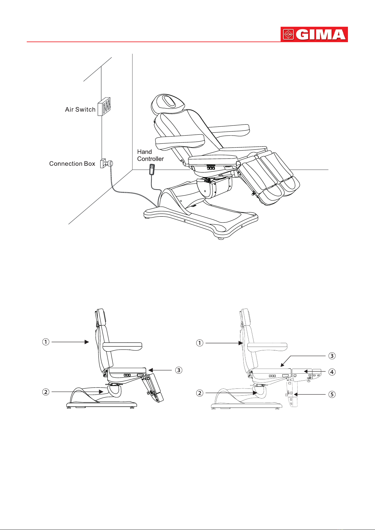
4. Power supply and controllers connections:
Connect the power supply, hand controller, and foot controller to the bed. Voltage and
frequency input shall be 110-120V/60Hz , 220-240V/50Hz.
Input ports: INPUT (for power supply), HAND CONTROLLER, FOOT CONTROLLER.
(as shown in the right picture)
5. Connect the plug with power supply properly. (Details as shown below)

11 ENGLISH
6 STRUCTURE OF ELECTRIC BEAUTY BED
• This beauty bed consists of control box, motor, hardware, plastic parts and leather. Among them, the control box is controlling the operation of
the motors and the hand controller.
• This beauty bed includes angle adjustment of the backrest, seat cushion, footrest, and lifting adjustment of the whole bed which is an overall
and integral structure.
(Details as shown below)
2246 2246A
angle adjustment of the backrest
lifting adjustment of the whole bed
angle adjustment of the seat
angle adjustment of the footrest (manual adjustment)
angle adjustment of the backrest
lifting adjustment of the whole bed
angle adjustment of the seat
angle adjustment of the footrest (right) (manual adjustment)
angle adjustment of the footrest (left) (manual adjustment)

12
7 OPERATION INSTRUCTION
StandardConguration(ButtonPanel)
DESCRIPTION OPERATION
1 Button for backrest adjustment Press button up (down), backrest moves up (down),
angle increases (decreases) at a constant speed.
2 Button for seat adjustment Press button up (down), seat inclines backward
(moves back to horizontal position).
3 Button for heigh control Press button up (down), seat moves up (down),
height increases (decreases) at a constant speed.
4 One-key reset button Press the button, the backrest will automatically move up to the maximum, the
seatcushionanglewillautomaticallymovetoat,footrestwillmovedownto
the minimum, the height of the bed will automatically reach the lowest position.
1. OptionalConguration
(Hand controller)
2. OptionalConguration
(Hand controller)
3. OptionalConguration
(Foot controller)
ENGLISH

13
DESCRIPTION OPERATION
1 Backrest moves up Backrest goes up smoothly by pressing the button.
2 Backrest moves down Backrest goes down smoothly by pressing the button.
3 Whole bed moves up The bed goes up smoothly by pressing the button.
4 Whole bed moves down The bed goes down smoothly by pressing the button.
5 Seat cushion up Seat inclining smoothly by pressing the button.
6 Seat cushion down Seatgoesatsmoothlybypressingthebutton.
7 (The right) footrest moves up Press the button, the right footrest will move up, its angle will be re-
duced to minimum.
8 (The right) footrest moves down Press the button, the right footrest will move down, its angle will be
moved to maximum.
9 (The left) footrest moves up Press the button, the left footrest will move up, its angle will be reduced
to minimum.
10 (The left) footrest moves down Press the button, the left footrest will move down, its angle will be
moved to maximum.
11 Enter the memory position setting (Option) The indicator light turns on after pressed the button for 2 seconds, then
enter the memory position setting state.
12 Indicator light of memory setting (Option)
13 Memory position setting 1(Option)
1. Pressing the button "SET" for 2 seconds to enter the memory po-
sition setting state, the memory position setting indicator is on. Set
the position you need, and pressing the button "Ml", the actions are
set into memory. Exiting the memory position setting state and the
indicator goes off.
2. Press the button to move to the memory action state automatically.
14 Safe-lock button Keep pressing the "safe-lock button" for about two seconds, lighting up
the green light around the button, all the buttons can not be operated
except safe-lock button . Keep pressing the safe-lock button for about
two seconds again, the green button lights go out, all the buttons return
to normal operation status.
15 Safe-lock button light
16 Memory position setting 2
(Option)
1. Pressing the button "SET" for 2 seconds to enter the memory po-
sition setting state, the memory position setting indicator is on. Set
the position you need, and pressing the button "M2", the actions are
set into memory. Exiting the memory position setting state and the
indicator goes off.
2. Press the button to move to the memory action state automatically.
17 Power indicator Hand controller are connected with power supply properly, indicator
light is on. Otherwise, it won't light.
18 One-key reset button
Press the button, the backrest angle will automatically move to the
maximum,theseatcushionanglewillautomaticallymovetoat,
footrest will move down to the maximum, the height of the bed will
automatically reach the lowest position.
19 Indicator light of heating function (Option) Pressing the button, the light is on, the heating function works; pressing
the button again, the light is off, the heating function stops.
20 Heating (Option)
Notes:
1. The memory position setting is only available for the models with memory function.
2. The heating function is only available for the models with heating function.
3.Differenthandcontrollersshouldbechosenaccordingtodifferentconguration.
ENGLISH

14
Adjust the instructions
This product graphic is only for display, the specic product structure please refer to the actual product.
Ifyoundtheheadrestsupportrodbecame
loose,pleasefollowtheabovestepstoxit.
Hold the
Handle Firmly Cross
Screwdriver
Tighten the Screw
Clockwise
Not allowed to operate seat cushion to tilt
when bed is in lowest position.
ENGLISH

15
Instruction for Tightening the Braking Block
(This is to tighten the braking block which the gear is frayed.)
Instruction for Replacing Braking Block
(This is to replace the braking block if the gear of braking block is absolutely worn out and it doesn't work any more.)
This product graphic is only for display, the specic product structure please refer to the actual product.
Step 1: Raise backrest to the
max. angle, and then loosen
the braking block by pushing
handle in the anticlockwise di-
rection as photo above.
Step 2: Hold handle with right
hand while unscrewing the M16
nut in clockwise direction with
open-end wrench.
Step 3: Press the M6 hexagon screw
withleftforengertopreventitfrom
rotating, while rotating handle by
360° anticlockwise with right hand.
This is to increase the distance A.
Step 4: Keep clamping frame horizontally
by holding handle with right hand, while
screwing the M16 nut with open-end
wrench in the anticlockwise direction.
Step 5: Tightening handle
in the clockwise direction as
photo above.
Step 1: Raise the backrest to
the max. angel, and then loos-
en the braking block by pushing
handle in the anticlockwise di-
rection as photo above.
Step 2: Hold the handle with
right hand, while unscrewing
the M16 nut in clockwise direc-
tion with open-end wrench.
Step 3: Press the M6 hexagon screw
withleftforengertopreventitfrom
rotating, while rotating the handle in
clockwise direction until handle could
be taken out.
Step 5: Reassemble a new braking
block as per step 4 to step1.
Step 4: Remove the braking
block, and then clamp the hex-
agon screw with wrench, while
unscrewing the M6 nut with
another wrench.
ENGLISH

16
8 TECHNICAL PARAMETERS
2246
2246A
9 MAINTENANCE
1. After every treatment, please use neutral reagent to clear the dust, stains on leather or the plastic cover. This is to prevent premature aging of
the leather and plastic cover.
2. Please lubricate the moving parts regularly (once a year)
Power AC 100-120V or AC 220-240V or AC 100-240V, 50/60Hz
Maximum Power 300W
Environment Temperature 0°C--+40°C
Relative Humidity 30%^-90%
Lifting Rated Load 175 KG
Package Size 1360x820x720MM (2246 / 2246A)
Net Weight 79KG (2246 / 2246A)
Gross Weight 92KG (2246 / 2246A)
ENGLISH

17
10 CIRCUIT SYSTEM CONNECTION DIAGRAM
11 TROUBLESHOOTING
If problem is still not solved after above operation, please contact maintenance center or supplier to solve it.
Disposal: The product must not be disposed of along with other domestic waste. The users must dispose of this equipment by bringing
it to a specic recycling point for electric and electronic equipment.
GIMA WARRANTY TERMS
The Gima 12-month standard B2B warranty applies.
Power
Hand controller (Option)
Button Panel
Foot controller (Option)
Backrest motor
Seat inclination motor
Whole bed lifting motor
Heating system (Option)
Control Box
THE FAULT PHENOMENON REASON SOLUTION
Can't rise or down normally
1. The power cord is unconnected or
not plugged well 1. Connect the power cord or plug it well
2. Poor quality of the hand controller or
foot controller 2. Replace the hand controller or foot controller
3. Poor quality of the rocker switch 3. Please contact maintenance center or supplier
for troubleshooting.
4. Poor quality of the control box
5. Repture of motor tail
6. Motor was damaged
7. Pressing the button, the bed did not
move 1.Putthemovablefootrestclosetothexedfootrest,makesure
the limit switch is closed, and then press the buttons again
2.Openthexedfootrestcoverandbackrestcoverrespectively,
check whether the two ends of the power cord are loose, if
the above situation occurs, please reconnect
3. If problem is still not solved after above operation, please
contact maintenance center or supplier to solve it.
Audio system error
1. Input/output connection error 1. Double check the connection of input/output
2. Audio control box error 2. Replace the defective parts
3. If problem is still not solved, please contact maintenance
center or supplier for troubleshooting.
3. Poor quality of the audio speaker
Abnormal Sound
1. The rotating parts are short
of lubricating oil 1. Add lubricating oil
2. Rotating positions (such as hinge,
POM sets) are short of lubricating oil 2. Add lubricating oil
3. Motor quality problems 3. Replace the motor
ENGLISH
This manual suits for next models
3
Table of contents
Other Gima Personal Care Product manuals