Gira 0441 00 User manual
GIRA
Info Multifunction Radio Transmitter
Installation Instructions
Multifunction Radio Transmitter 05/01 Page: 1 of 8
Flush-Mounted Four-Channel
Multifunction Radio Transmitter Order No.: 0441 00
A
1x
CR2032
cd
Function
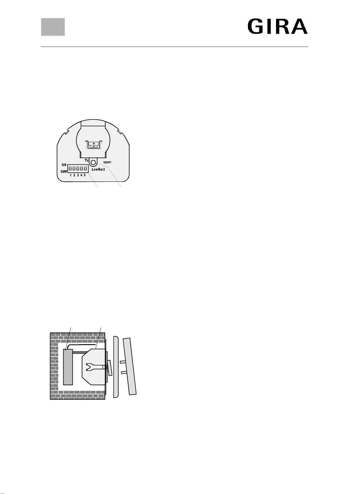
This multifunction radio transmitter (Fig. A: Front view) is a
battery-operated four-channel radio transmitter for the
extension of an existing radio control installation.
At its four inputs E1 to E4 (see Fig. C), the multifunction
radio transmitter detects switching states of potential-free
installation switches or push-buttons.
It transmits radio data telegrams which can be decoded by
all radio control receivers.
A 5-digit microswitch (Fig. A c) facilitates the selection of
eight different modes of operation.
A red LED (Fig. A d) indicates the transmission of radio
telegrams (slow unsymmetrical blinking, 4 Hz) or an empty
battery "LowBatt" (quick symmetrical blinking, 10 Hz).
Safety instructions
Attention: Electrical equipment must be installed and fitted by qualified electricians only.
To avoid possible damage to the electronic circuitry by electrostatic discharge, observe the pre-
cautions for the handling of components sensitive to electrostatic discharge when changing the battery
or operating the microswitches.
B
cd
Installation
Install the multifunction transmitter (Fig. B c) in a surface-
mounted or flush-mounted box behind a potential-free
installation switch or push-button (Fig. B d).
The multifunction transmitter has no pull-relief.
Important
To avoid saturation of the radio receivers (actuators), the
distance between the transmitter and the receiver must be
approximately 1 m.
Cable
The eight-wire cable serves to connect potential-free
installation switches and push-buttons.
Wires not used should be insulated and must not be brought
into contact with live parts to prevent the device from being
irreparably damaged.

GIRA
Info Multifunction Radio Transmitter
Installation Instructions
Multifunction Radio Transmitter 05/01 Page: 2 of 8
C
PK
E4
GY
E3
GN
E2
YE
E1
WH
123456789
YEGNGYPK
Plug the connector of the eight-wire multi-colour cable and
the white antenna into the multifunction transmitter (Fig. C:
Rear view).
Wire colour assignment:
Yellow (YE) and yellow/black: input E1.
Green (GN) and green/black: input E2.
Grey (GY) and grey/black: input E3.
Pink (PK) and pink/black: input E4.
The black-striped wires form a common reference potential.
Antenna
To obtain maximum radio transmitting power unroll and
install the antenna in a straight line.
Keep away from large-surface metal parts (e. g. metal door
frame). Do not strip, shorten or extend the white antenna.
D
1x
CR2032
Battery
The multifunction transmitter is powered by a lithium button
cell (CR 2032). The device comes with the battery inserted.
Safety and disposal instructions
Attention:
Keep button cells away from children. Seek medical
advice immediately when button cells have been
swallowed.
Remove used batteries immediately and discard without
polluting the environment.
Replace battery by identical or equivalent types only.
E
Battery Change
1. Use a screwdriver and open the battery compartment (Fig.
D) carefully.
2. Remove the exhausted battery.
3. Put a fresh battery on the ⊕contact of the battery holder
first, as shown in Fig. E. Then press slightly to snap the
battery in place. Ensure correct polarity (⊕= up). Keep the
battery grease-free.
4. Close the battery compartment.
GIRA
Info Multifunction Radio Transmitter
Installation Instructions
Multifunction Radio Transmitter 05/01 Page: 3 of 8
F
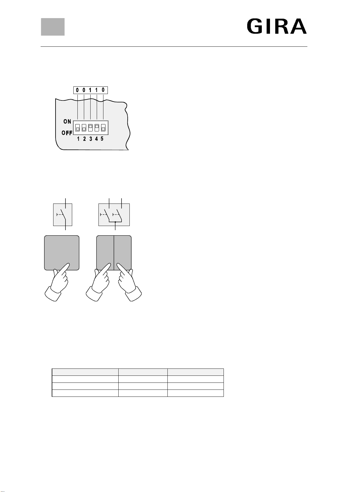
Modes of operation
The following pages explain the eight selectable modes of
operation with their associated microswitch positions. They
are divided into:
Modes 1-2: Connection of installation push-buttons.
Modes 3-4: Connection of installation switches.
Modes 5-8: Lightscape operation using installation push-
buttons.
For the microswitches, position 1 is ON and position 0 is
OFF.
For example, Figure F shows microswitch position 00110 for
mode 4.
G1 G2
Operation
For the connection of installation push-buttons, a distinction
is made between single-rocker and double-rocker operation:
Single-rocker operation using installation push-buttons:
Connection of a push-button to a wire pair of the multifunc-
tion transmitter. The rocker of the push-button can be used
for switching on and off, or for increasing or lowering of the
brightness (Fig. G1).
Double-rocker operation using installation push-
buttons:
Connection of a dual push-button, for example, to two wire
pairs of the multifunction transmitter. One rocker serves to
switch on, increase the brightness or move up a blind; the
other one to switch off, dim the lights or to lower a blind (Fig.
G2).
Actuation Times
When installation push-buttons are connected, a distinction is made between long (> 1 s) and short
actuation (< 1 s). Accordingly, different reactions of the radio receivers are possible:
short long
Switching actuator Switching on/off Switching on/off
Dimming actuator Switching on/off Brighter/darker
Venetian blind actuator Slat adjustment Cont. up/down run
Important
Venetian blind operation is only possible with the double rocker element (no. 2) and in the lightscape
(nos. 5-8) modes.
The maximum transmission time is 12 s, even though another push-button connected is still being
pressed.

GIRA
Info Multifunction Radio Transmitter
Installation Instructions
Multifunction Radio Transmitter 05/01 Page: 4 of 8
1)
2)
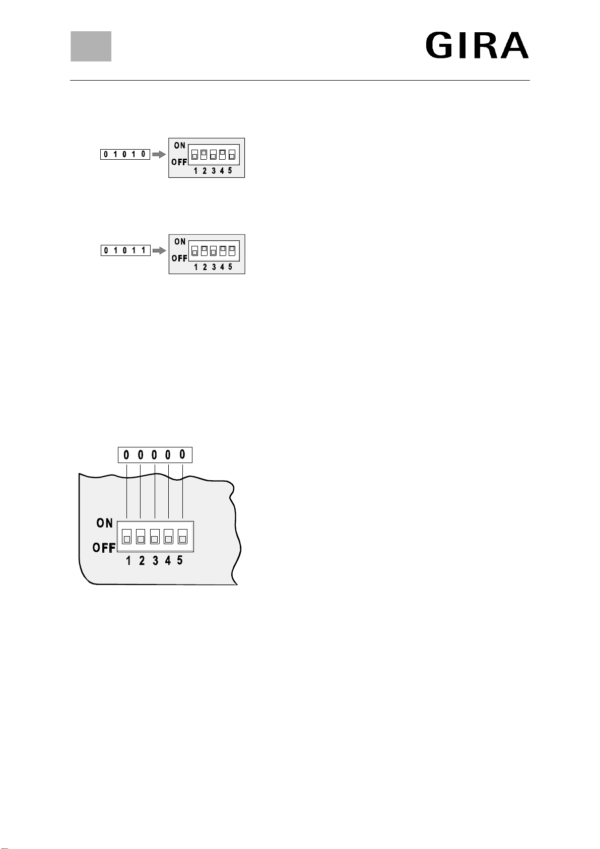
Mode Selection
1)Single-rocker operation using installation push-
buttons
Single-rocker switching or dimming using up to four
installation push-buttons (E1-E4).
Actuation leads to switching over (toggling) of the
telegram type (on/off, brighter/darker) in the multifunction
transmitter. Toggling takes place in the transmitter.
Therefore, to obtain the desired response, the multi-
function transmitter will possibly have to be actuated twice
after local operation or when the receiver has been
controlled by a different transmitter.
2)Double-rocker operation using installation push-
buttons
Double-rocker switching, dimming or blind operation using
installation push-buttons. Inputs E1/E2 and E3/E4 form
one channel each.
3)
4)
3)Connection of installation switches (normally open
contacts)
Inputs E1 to E4 form one switching channel for controlling
radio receivers with installation switches (normally open
contacts). The switching contact acts in the same way as
the switch connected to the multifunction transmitter.
4)Connection of installation switches (normally closed
contacts)
Inputs E1 to E4 form one switching channel for controlling
radio receivers with installation switches (normally closed
contacts). The switching action of the contact is opposed
to that of the switch connected to the multifunction
transmitter.
5)
6)
5) ALL-ON, ALL-OFF, lightscapes 1 and 2
E1: Switching ON all programmed receivers.
(ALL-ON function).
E2: Switching OFF all programmed receivers.
(ALL-OFF function).
E3: Calling or saving lightscape 1.
E4: Calling or saving lightscape 2.
6) ALL-OFF, lightscapes 1 to 3
E1: Switching OFF all programmed receivers.
(ALL-OFF function).
E2: Calling or saving lightscape 1.
E3: Calling or saving lightscape 2.
E4: Calling or saving lightscape 3.
GIRA
Info Multifunction Radio Transmitter
Installation Instructions
Multifunction Radio Transmitter 05/01 Page: 5 of 8
7)
8)
7) ALL-OFF, lightscapes 3 to 5
E1: Switching OFF all programmed receivers.
(ALL-OFF function).
E2: Calling or saving lightscape 3.
E3: Calling or saving lightscape 4.
E4: Calling or saving lightscape 5.
8) Lightscapes 1-4
E1 to E4: Calling or saving lightscapes 1 to 4.
Other microswitch positions not described are without
function.
Programming of radio receivers
A multifunction transmitter channel can be programmed into
any number of radio receivers. Programming affects only the
radio receiver.
During programming of a transmitter, the sensitivity of the
receiver is reduced to approx. 5 m. The distance between
the radio receiver and the radio transmitter to be pro-
grammed should therefore be between 0.5 m and 5 m.
H
Procedure
1. Switch the radio receiver into the programming mode.
(Refer to the "Radio Receiver" operating instructions).
2a. Programming of modes 1 and 2:
- Set microswitch to the desired position.
- Press the installation pushbutton of the desired input
for at least 1 s.
Note: For double rocker modes, press one push-button
per radio channel only.
2b. Programming of modes 3 and 4
- Set microswitch first to position 00000 (refer to Fig. H).
- Press the connected switch of the desired input for at
least 1 s.
- Now, set the associated microswitch position.
2c. Programming of modes 5 to 8:
- Set microswitch to the desired position.
- Depending on the function selected, press the
lightscape key for at least 3 s or the ALL-ON or ALL-
OFF key for at least 10 s.
Important:
When a lightscape key is programmed, the ALL-ON or
ALL-OFF key will be stored automatically by the radio
receiver.
(Refer to the "ALL-ON/ALL-OFF" or "Calling/ Saving a
Lightscape" chapters.)
3. Set the radio receiver to the operation mode. (Refer to
the "Radio Receiver" operating instructions).

GIRA
Info Multifunction Radio Transmitter
Installation Instructions
Multifunction Radio Transmitter 05/01 Page: 6 of 8
Clearing of channels
Reprogramming of the transmitting channel to be deleted cancels the old assignment in the radio
receiver.
ALL-ON/ALL-OFF (for modes 5 to 7 only)
When programming the ALL-ON or ALL-OFF key, make sure the lightscape is on or off if ALL-ON or
ALL-OFF assignments are already available. Otherwise, the existing lightscape will be changed.
(Refer to "Changing ALL-ON/ALL-OFF".)
Changing ALL-ON/ALL-OFF
Example:
One of the receivers (bathroom light) is supposed not to respond to the ALL-ON function, while all the
other receivers switch on the light.
Procedure
1. Press the ALL-ON key for at least 1 s. This switches on all programmed radio receivers.
2. Set your lights in the way you expect them to respond later when the ALL-ON key is pressed, i. e.
since all receivers are on, now switch OFF the light in the bathroom, for example.
3. Press the ALL-ON key for at least 10 s to save the light setting.
Important
First of all, the previous light setting is recalled (do not release the key). After approx. 10 s, the
new setting will be activated and saved.
This completes the new assignment of the ALL-ON key. To change the ALL-OFF key, proceed
accordingly.
Recalling/saving a lightscape (for modes 5 to 8 only)
Before you can save (long actuation for at least 3 s) or call (short actuation) a lightscape, the
lightscape key must have been programmed (refer to "Programming of Radio Receivers") and the
lightscape set.
Setting or changing a lightscape
1. Set your desired lightscape (e. g. light 1 = 50 % brightness, light 2 = 70 % brightness, Venetian
blind up).
2. Press the desired lightscape key for at least 3 s.
Important
First of all, the previous lightscape is called (do not release the key). After approx. 3 s, the new
lightscape will be activated and saved.
Important for Venetian blinds
If a Venetian blind is not in one of its end positions or not on its way to such position while a lightscape
is being saved, this blind will not be stored in the lightscape.
GIRA
Info Multifunction Radio Transmitter
Installation Instructions
Multifunction Radio Transmitter 05/01 Page: 7 of 8
I
PK
E4
GY
E3
GN
E2
YE
E1
WH
123456789
YEGNGYPK
N
1
L
Prog
OFF
ON
Prog Antenne
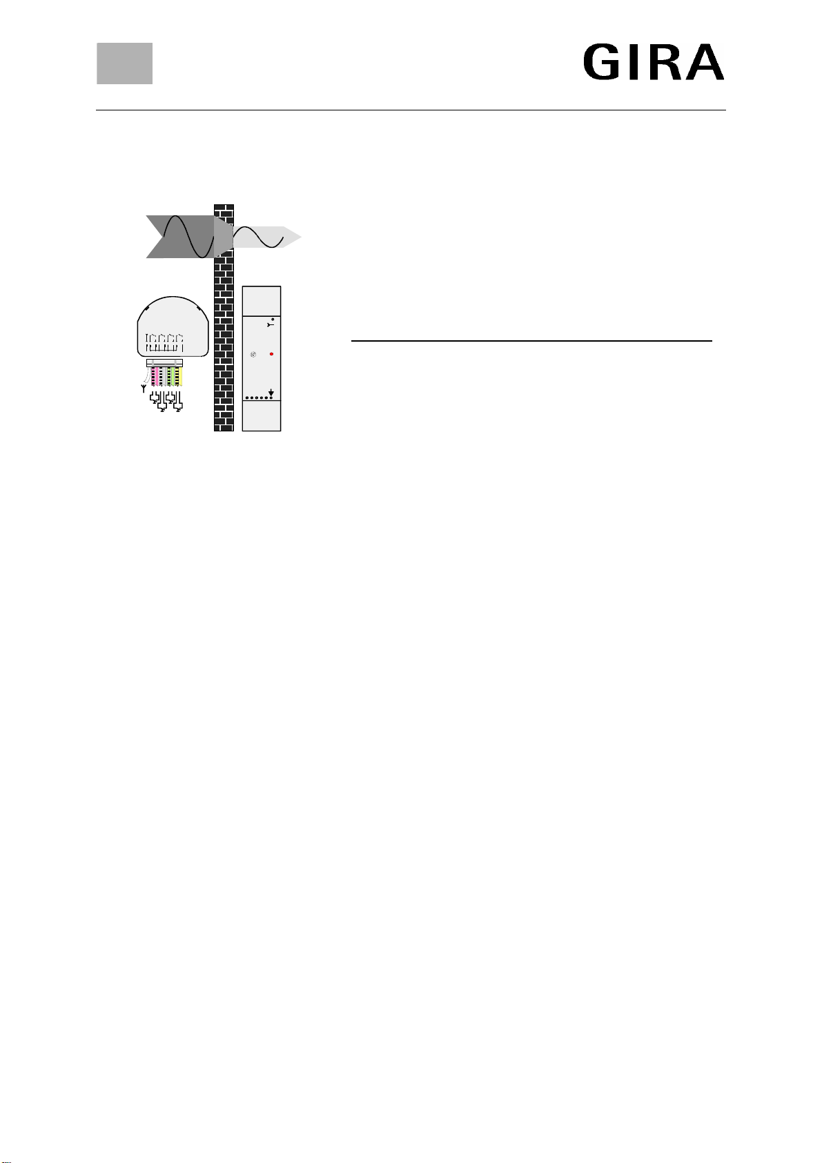
Radio transmission
The radio signals are transmitted on non-exclusive
frequencies. Transmission disturbances can therefore
not be excluded.
The transmission by radio is not suitable for safety
applications such as emergency shut-off and
emergency calling functions.
Dry Materials Penetration
Timber, gypsum, gypsum plaster boards approx. 90 %
Brickwork, particle boards approx. 70 %
Reinforced concrete approx. 30 %
Metal, metal grating, aluminium cladding approx. 10 %
Notes on radio operation
•For interconnection of this radio installation with other communication networks, please observe
the respective telecommunication legislation in your country.
•This radio installation must not be used for communication across estate boundaries.
•For operation within Germany, observe the instructions of the General Approval published in
Amtsblatt. Vfg 73/2000.
This multifunction transmitter controller is approved for use in all EU and EFTA states.
Specifications
Power supply: 3 VDC
Battery: 1 x CR 2032 lithium cell
Length of connecting lines: approx. 290 mm
Transmit frequency: 433.42 MHz, ASK
Transmitting range: 100 m max. (in the free field)
Coding: > 109different possibilities
Protective system: IP 20
Temperature range: approx. -20 °C to +55 °C
Relative atmospheric
humidity: 65 % max. (without condensation)
Dimensions (L x W x H): 45 x 40 x 10 mm

GIRA
Info Multifunction Radio Transmitter
Installation Instructions
Multifunction Radio Transmitter 05/01 Page: 8 of 8
Acceptance of guarantee
We accept the guarantee in accordance with the corresponding legal provisions.
Please return the unit postage paid to our central service department giving a brief description
of the fault:
Gira
Giersiepen GmbH & Co. KG
Service Center
Dahlienstrasse 12
D-42477 Radevormwald
The CE sign is a free trade sign addressed exclusively to the authorities and does not include
any warranty of any properties.
Gira
Giersiepen GmbH & Co. KG
Postfach 1220
D-42461 Radevormwald
Telefon: +49 / 21 95 / 602 - 0
Telefax: +49 / 21 95 / 602 - 339
Internet: www.gira.de
Table of contents
Other Gira Transmitter manuals


