Gira 1111 00 User manual

Radio wall-transmitter flat design 1-g
Order-No. : 1111 00
Radio wall-transmitter flat design 3-g
Order-No. : 1113 00
Operating instructions
1 Safety instructions
Electrical equipment may only be installed and fitted by electrically skilled persons.
Failure to observe the instructions may cause damage to the device and result in fire and
other hazards.
Keep button cells out of reach of children! If button cells are swallowed, get medical help
immediately.
Risk of explosion! Do not throw batteries into fire.
Risk of explosion! Do not recharge batteries.
The radio communication takes place via a non-exclusively available transmission path,
and is therefore not suitable for safety-related applications, such as emergency stop and
emergency call.
These instructions are an integral part of the product, and must remain with the end
customer.
2 Device components
Figure 1
(1) Wall transmitter
(2) Operating rockers
3 Function
System information
By statute, the transmitting power, the reception characteristics and the antenna cannot be
changed.
The device may be operated in all EU and EFTA countries.
The declaration of conformity can be viewed on our website.
1/9
32532712 28.09.2011
Radio wall transmitter, flat design
10499114 I00
Radio bus system

The range of a radio system from the transmitter to the receiver depends on various
circumstances.
The range of the system can be optimised by selecting the optimal installation location, taking
into account the structural circumstances.
Figure 2: Reduced range due to structural obstacles
Example of penetration of various materials:
Material Penetration
Wood, Plaster, Plasterboard approx. 90%
Brick, Chipboard approx. 70%
Reinforced concrete approx. 30%
Metal, Metal grid approx. 10%
Rain, Snow approx. 1-40%
Intended use
- Radio transmitter for transmission of switching, dimming, blind movement and light scene
commands
- Surface-mounted
- Operation with suitable radio actuators
Product characteristics
- Each two opposite buttons belong to one channel
- Functions can be set with 3gang function switch
- Special functions "All Off" or "Light scene" can be assigned to individual buttons
- Battery-powered device
32532712 10499114 I00 28.09.2011 2/9
Radio bus system
Radio wall transmitter, flat design
4 Operation
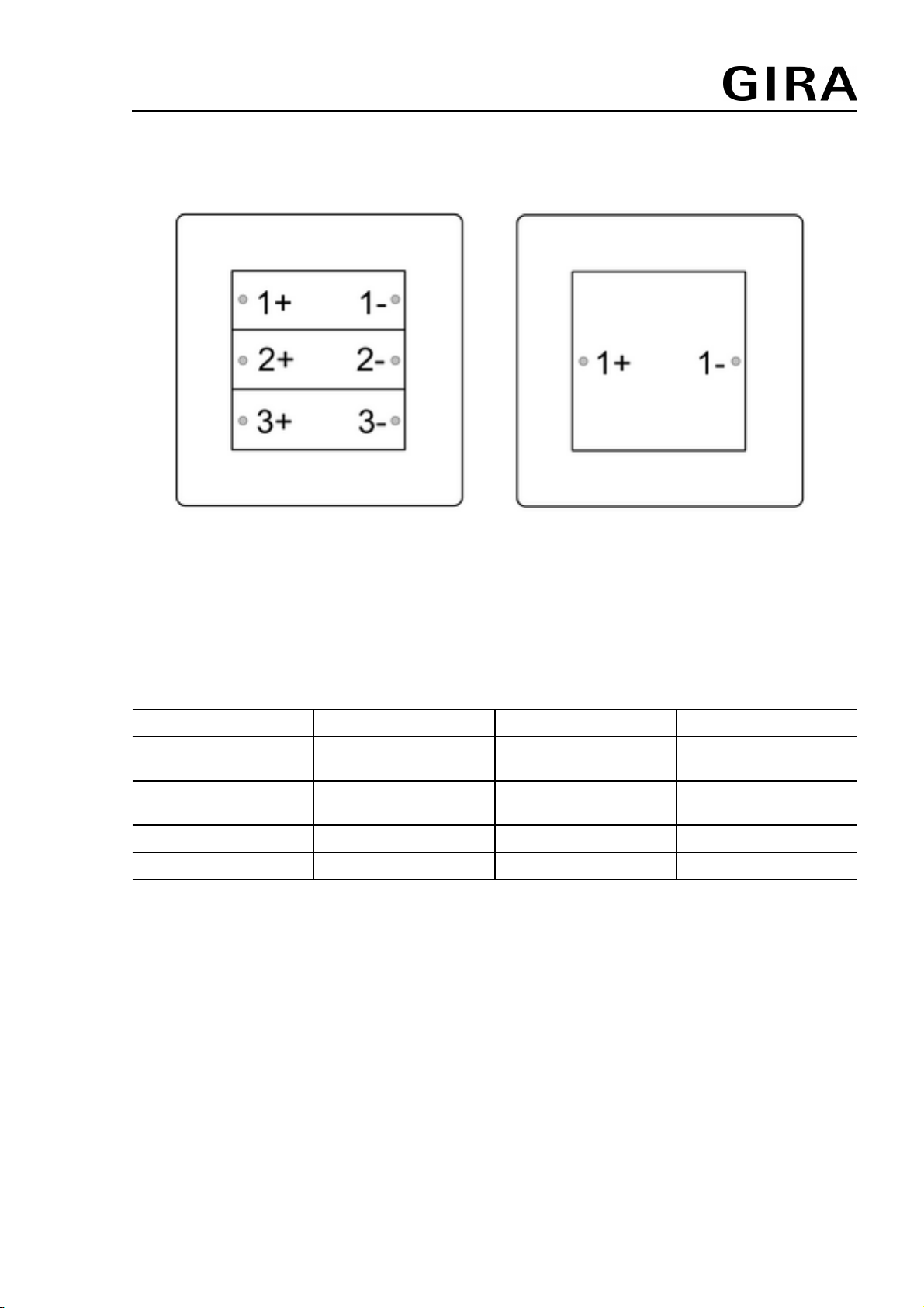
Channel assignment of the wall transmitter
Figure 3: Channel assignment
Sending radio telegrams
o Press channel button, e.g. 1+, to transmit a radio telegram.
The corresponding LED lights up as an acknowledgement.
As long as no light scene functions were selected, the following responses occur, depending on
the type of receiver:
Button Length Lighting Venetian blind
X+ less than 1 second Switch on Slat
adjustment
X- less than 1 second Switch off Slat
adjustment
X+ longer than 1 second brighter Blind moves up
X- longer than 1 second darker Blind moves down
i The maximum transmitting length is 12 seconds, even if another button is pressed after
that.
i If more than one button is pressed at the same time, the radio telegram of only one button
is transmitted.
Calling up light scenes
Light scene button has been taught (see Commissioning).
o Press the light scene button for shorter than 3 seconds.
Receivers switch to the stored light scene value.
Save light scene
Light scene button has been taught (see Commissioning).
o Set the required lighting situation.
o Press the light scene button for longer than 3 seconds.
First the old light scene is called up; do not release the button during this. After about
3 seconds the new light scene is saved and activated.
32532712 10499114 I00 28.09.2011 3/9
Radio bus system
Radio wall transmitter, flat design

i If during saving of a light scene the blind is not in an end position, or is on the way there,
then that blind is not integrated into the light scene.
Call up All Off
In the teaching procedure for a channel button or a light scene button, the All Off button of the
receiver is automatically also taught, with the exception of radio blind actuators.
Function switch 1 is in the OFF position (see Commissioning).
o Press button 1- longer than 1 second.
The loads at all taught receivers are switched off.
5 Information for electrically skilled persons
5.1 Fitting and electrical connection
Connecting and mounting the device
Maintain a distance of at least 1 m between transmitter and receiver.
Maintain distance from large-area metal objects, e.g. metallic door frames.
i Perform commissioning and teaching procedures before installation (see Commissioning
chapter).
o Inset battery if necessary (see section Changing the battery).
Screw mounting
Figure 4: Screw mounting
o Using a screwdriver, carefully remove operating rockers (2).
o Insert supplied threaded sleeves (4) through the screw holes from the rear.
o Mount wall transmitter (1) directly to the wall using the screws (5) and anchors (3).
o Attach operating rockers.
Glue mounting
In order to glue the wall transmitter directly to an even surface, e.g. glass, a base plate is
available (see chapter 6.3. Accessories).
32532712 10499114 I00 28.09.2011 4/9
Radio bus system
Radio wall transmitter, flat design

Figure 5: Glue mounting
o Glue base plate (6) directly to the surface.
o Using a screwdriver, carefully remove operating rockers (2).
o Fix wall transmitter (1) with the screws (7).
o Attach operating rockers.
Figure 6: Glue mounting in a multiple combination
i In order to use the wall transmitter in a multiple combination with glue mounting, the edge
pieces (8) of neighbouring base plates have to be broken off at the predetermined breaking
points.
32532712 10499114 I00 28.09.2011 5/9
Radio bus system
Radio wall transmitter, flat design

Changing the battery
WARNING!
Risk of chemical burns.
Batteries can burst and leak.
Replace batteries only with an identical or equivalent type.
o Unscrew wall transmitter from the base plate or the wall and remove it (see section
Connecting and mounting the device).
Figure 7: Remove battery
o Remove empty battery carefully using a screwdriver.
Figure 8: Insert battery
i Keep contacts of batteries and device free of grease.
o Apply new battery to the positive contact of the battery holder. Observe polarity: the
positive pole of the battery must be at the top.
o Press gently on battery to snap it in.
o Mount wall transmitter on base plate.
32532712 10499114 I00 28.09.2011 6/9
Radio bus system
Radio wall transmitter, flat design

o Press any button for approx. 1 second.
5.2 Commissioning
Setting functions
Wall transmitter is unscrewed from the base plate / the wall.
Figure 9: Function switch
i In the state as delivered all function switches are set to the ON position.
o Select functions of the buttons with the function switches according to the following table .
Function switch Button ON OFF
1 Button 1-
Button 1+
Channel 1-
Channel 1+
All off
Light scene 1
2 Button 2-
Button 2+
Channel 2-
Channel 2+
Light scene 2
Light scene 3
3 Button 3-
Button 3+
Channel 3-
Channel 3+
Light scene 4
Light scene 5
Teaching transmitter in radio receiver
In order for a receiver to understand a radio telegram from the transmitter, the receiver has to
"learn" this radio telegram. A channel of the transmitter can be taught in any number of
receivers. The teaching procedure only results in an assignment in the receiver.
When teaching a transmitter, the range of the receiver is reduced to about 5 m. The distance
between the receiver and the transmitter being taught should therefore be between 0.5 m and
5 m.
The function switch for the channel being taught is set to ON.
o Switch radio receiver to programming mode (see instructions for receiver).
o Press the "+" or "-" button of the desired channel longer than 1 second.
o Exit programming mode of the receiver (see instructions for the receiver).
The channel of the transmitter has now been taught in the radio receiver.
Teaching a light scene button
The function switch for button being taught is set to OFF.
o Switch receiver to programming mode (see instructions for receiver).
o Press the light scene button for longer than 3 seconds.
o Exit programming mode of the receiver (see instructions for the receiver).
Light scene button has been taught.
Deleting All Off
If a certain receiver should not respond to the All Off button, then this function has to be
deleted.
o Switch receiver to programming mode (see instructions for receiver).
32532712 10499114 I00 28.09.2011 7/9
Radio bus system
Radio wall transmitter, flat design

o Press All Off button 1- for longer than 10 seconds.
Function has been deleted.
o Exit programming mode of the receiver (see instructions for the receiver).
6 Appendix
Remove empty batteries immediately and dispose of in an environmentally friendly
manner. Do not throw batteries into household waste. Consult your local authorities
about environmentally friendly disposal. According to statutory provisions, the end
consumer is obligated to return used batteries.
6.1 Technical data
Rated voltage DC 3 V
Battery type 1×lithium CR 2032
Ambient temperature 0 ... +55 °C
Relative humidity max. 80 % (No moisture condensation)
Protection rating IP 20
Carrier frequency 433.42 MHz (ASK)
Transmitting range in free field typical 30 m
Transmitting power < 10 mW
6.2 Troubleshooting
After a brief button-press the LEDs flash five times.
Cause: battery in the wall transmitter is almost empty.
Change battery (see section changing the battery).
Receiver does not respond, or only sometimes.
Cause 1: Radio range exceeded. Structural obstacles reduce the range.
Using a radio repeater.
Cause 2: function switches are in the wrong position.
Check positions of function switches.
6.3 Accessories
Base plate set for System 55 radio wall
transmitters, flat design
Order-No. 1110 00
6.4 Warranty
The warranty is provided in accordance with statutory requirements via the specialist trade.
Please submit or send faulty devices postage paid together with an error description to your
responsible salesperson (specialist trade/installation company/electrical specialist trade). They
will forward the devices to the Gira Service Center.
32532712 10499114 I00 28.09.2011 8/9
Radio bus system
Radio wall transmitter, flat design
Gira
Giersiepen GmbH & Co. KG
Elektro-Installations-
Systeme
Industriegebiet Mermbach
Dahlienstraße
42477 Radevormwald
Postfach 12 20
42461 Radevormwald
Deutschland
Tel +49(0)21 95 - 602-0
Fax +49(0)21 95 - 602-191
www.gira.de
32532712 10499114 I00 28.09.2011 9/9
Radio bus system
Radio wall transmitter, flat design
This manual suits for next models
1
Table of contents
Other Gira Transmitter manuals


