Global WF 9995-AE Parts list manual

WF 9995-AE
SINGLE NEEDLE,
TOP
AND BOTTOM FEED
LOCKSTITCH
SEWING MACHINE SPECIALLY
DESIGNED
FOR
TRIMMING
AND
BINDING,
WITH
ALTERNATING OUTSIDE PRESSERFOOT.
AND EDGE
CUTTER
INSTRUCTION / OPERATING MANUAL
PARTS MANUAL

CONTENTS
Instruction Manual
1.
.
MAIN
SPECIFICATIONS
...........
-i
.......
........
..........
.
......................
.
.....
..
....
.
...
......
l
2.
INSTALL
THE
MOTOR...
..........
..
............
..
...
......
......
....................
...
............
.....1
3.
CONNECT
THE
CLUTCH LEVER
WITH
THE
PEDAL... ;
......................
.........
.. .. ......l
;
4.
PREPARATIOJi
AND LUBRICATION.... ............
............
....
.......
...
.....
...
............
....l
5.
REPLACE NEEDLES...
......................
..
...............
... ... .. ........
...........
......
..
...
........2
6.
RUN-IN
OPERATION
...................................
.... ..
.....
.
.........................
...........
....2
7.
SET
STITCH LENGTH
AND
REVERSE FEEDING ....
...........
.....
....
..........
..........
.3
8. THREADING
......................................
.'
........
.
.........
..
.
.....
...
-
...................
.....
...3
9.
WINDING
ADJUSTMENT
...........................................................
·
.............
....
.....3
10.
POSITION PRESSER BAR
..
.
.......
,.
........:
...........
,
... ....,
.
..
....... ..... ..
.....
.... ...
............
.4
11.
ADJUST
THE
PRESSURE
OF
PRESSER FOOT
....
....
................
...
..................
:
........
4
12.
ADJUST THREAD TENSION
.....
.-
....
.
...................................
.
...............
.
...............
4
13.
ADJUST THREAD
TAKE
-
UP
SPRING
......
....,
......................................................
5
14.
ADJUST THREAD GUIDE
AND
THREAD TENSION
...................
..
...........................
6
15.
TIME
NEEDLE
TO
ROTAING
HOOK
.................................................................
6
16. REPLACE
ROTATING
HOOK
...........................................................................
7
17.
ADJUST
THE
HEIGHT
OF
FEED
DOG
.................
..
...........................
...... .
.............
7
18.
ADJUST
THE
POSITION
OF
FEED
DOG
............................................................
8
19.
TIME
FEED MOTION
TO
NEEDLE MOTION
......................................................
8
20.
ADJUST OPENING TIME
OF
THE TENSION DISCS
.............................................
9
21.
LUBRICATION ADJUSTMENT
....................
.....
:
..............................................
9
22.
INSTALLING
OF
THE NEDDLE
PLATE
..........
:
.................................................
JO
23.
CLOTH
CUTTING KNIFE
...............................................................................
10
24.
REGULAR CLEANING.
..
...
............
......
.....
.............
..
....................................
..
11
Parts Catalog
A.
ARM
BED
AND
ITS
ACCESSORIES
.........................
~
..........................................
12
H.
SEWING
MECHANISM..·
.....
......·-
·····················
...................
.
:
..............................
15
C.
STITCH
REGULATOR
MECHANISM.. .
................
..
............................
:
.......
.......
.....
18
D.
FEEDING
AND
FEED LIFTING MECHANISM
...................................
..
...................
20
E.
PRESSER FOOT
MECI-IANISM
.......
............
..
..
....................................................
22
F.
TOP
FEED
MECHANISM
..................................................................................
24
G.
KN!
FE
MECHANISM .. .
............................
..
.....
.
..........................................
....
27
H.
OIL
LUBRICATION
MECHANISM
..............
.......:
.........................................
1
........
29
I.
OIL
RESERVOIR
AND
OTHER ACCESSORIES
......................................................
31
From the library of Superior Sewing Machine & Supply LLC - www.supsew.com

1.
MAIN SPECIFICATIONS
I) Sewing material: Light-Medium material
2) Max. sewing speed: 2000 spm.
3) Stitch length: 0-8mm.
4)
Needle bar stroke: 35mm.
5)
Presser fool lift: 6mm (by hand) 13mm (by knee ).
6) Needle:
DPX
17
No.18-No.22
7) Lubrication: Automatic
8) Width to be cut: Standard8.0mm. Special6,10,12mm
9) Reverse feeding mechanism: Have
2.INSTALL
THE
MOTOR ( Fig.1 )
Align
Motor
Pulley Groove ( B ) and Balance Wheel Groove ( A ) by
moving
the
motor
leftward or
rightward.
X
~---
--
·--------
Fig. 1 Fig. 2
3.
CONNECT
THE
CLUTCH LEVER WITH THE
PEDAL
( Fig.2 )
1)
The optimum tilt angle
of
pedal
(A)
is approximately
15
deg.
2) Adjust Clutch
Cover
(
D)
so that Clutch-Lever ( C ) and Draw Bar ( B ) run in line.
3) The balance wheel should rotate counter-clockwise when viewed from the outside
of
Balance Wheel ( G ).
The direction
of
the
motor pulley rotation can be reversed by reversing ( turning
over
180
deg.)
the
power
plug
of
the motor.
4) Adjust the tension
of
V-belt (
F)
by
turning Motor Vertical Position Screw ( E ).
The
proper tension
of
the
V-belt
is
a slack
of
10-20mm when the belt is depressed at the center
of
the belt by finger.
4. PREPARATIONAND LUBRICATION (
Fig.3)
l)
Cleaning the machine
Before
leaving the factory, the machine parts are coated with rust-preventive grease, which may be
hardened and contaminated
by
dust during storage and shipment. This grease must be removed with gasoline.
2)
Examination
Though every machine
is
confirmed
by
strict inspection and test before leaving the factory, the machine
parts may be loose
or
deformed after long distance transportation with
jo
l
t.
A thorough examination must be
performed after cleaning the machine. Turn the balance wheel to see
if
there
is
running obstruction, parts
collision, uneven resistance or abnormal noise.
If
these exist, adjustment must be made accordingly before
·-
·-
1 --·
From the library of Superior Sewing Machine & Supply LLC - www.supsew.com

run-in operation.
3) Oiling
(1) Required amount
of
oil.
Line ( A ) on the oil reservoir: Max. oil level. Line (
8 )
on the oil reservoir: Min. oil level.
If
oil level
goes down under line ( B ), oil cannot be distributed to each part
of
the machine, thus causing the parts a
seizure.
(2) Replenishing
Always use only No.18 special machine oil for high speed sewing. Be sure to replenish oil to Line ( A )
before sta1iing operation.
(3) Replacing oil
To
replace oil,
remove
Screw ( C ) to drain oil. After completely draining
off
oil, clean the oil reservoir
and securely tighten Screw ( C ), then
fill
the reservoir with fresh oil.
~
--
-
---
--
- -
----
~
X
)(
I
A B
C
/'
a b
C
Long
groove
Fig.3
Fig.4
5.
REPLACE NEEDLES ( Fig.4)
Turn the balance wheel to lift needle bar to the upper end
of
its
stroke. Loosen Needle Clamp Screw A.
While keeping the long groove
of
the needle leftward fully insert the needle shank up to
the
bottom
of
the
needle socket. Then tighten Needle Clamp Screw A.
Note: Fig. (b): insufficient insertion.
Fig. (c): wrong direction
of
long groove.
6.
RUN-IN OPERATION ( Fig.
5)
Run-in operation
is
required for a new sewing machine, or a sewing machine left
out
operation for a
considerable length
ohime.
1)
Remove Rubber Plugs ( A ) on the top
of
the arm and replenish sufficient amount
of
oil.
2) Lift Presser
Foot
( B ).
3) Run the machine at a low speed ( 1000-lS00spm ) to check oil distributing condition through Oil
Check Window ( C
).
4) Perform run-in operation at 1000-l SO0spm for 30minutes. After a lapse
of
one month
of
service during
which the working speed
is
increased gradually and the machine runs sufficiently well, the high speed
2000spm can be adopted according to the nature
of
the work.
-·2
--
-
From the library of Superior Sewing Machine & Supply LLC - www.supsew.com

Fig.5 Fig.6
7. SET STITCH LENGTH AND REVERSE FEEDING (
Fig.6)
I) Stitch length can be set
by
turning Dial
(A).
2) The figures on Face ( B )
of
dial show stitch length
in
mm.
3) Reverse feeding starts when Reverse Feed Lever ( C )
is
depressed, and the machine will feed forward
again ifReverse Feed lever (
C)
is
released.
8.
THREADING (
Fig.7)
To
thread the needle thread, raise needle bar to the upper end
of
its stroke, lead the thread from spool and
perform threading
as
shown
in
Fig.7 .
To
draw the bobbin thread, hold the end
of
the needle thread and turn
the
balance wheel to lower the needle bar and then to lift it to its highest position. Pull the needle thread and the
bobbin thread
is
drawn up. Put the ends
of
needle thread and bobbin thread frontward under presser foot.
a
b
Fig. 7
9.
WINDINGADJUSTMENT ( Fig.8 )
- 3 -
A----~
8
---~
m
C
d
Fig.8
From the library of Superior Sewing Machine & Supply LLC - www.supsew.com

1)
The wound bobbin thread should be neat and tight,
if
not, adjust the winding tension by turning
Tension Stt!d Nut
(A)
of
bobbin winder tension bracket.
Note: nylon
or
polyester thread should
be
wound with little tension, otherwise, Bobbin ( D ) might.break
or deform.
2) When the wound thread layer does not present a cylindrical shape
as
shown in Fig.8 (
a)
, loosen Set
Screw ( B )
of
bobbin winder tension bracket and slide Bracket ( C ) leftward or rightward.
If
thread
is
wound
as
shown
in
Fig.8 ( b ), move the bracket rightward, but
if
thread
is
wound as shown in Fig.8 ( c ), move the
bracket leftward.
After adequately positioning the bracket, tighten Set Screw ( B
).
3) Do not overfill the bobbin.
The
optimum length
of
thread will fill about 80%
of
bobbin capacity. This can be
adjusted by Adjusting Screw (
E)
of
bobbin winder stop latch.
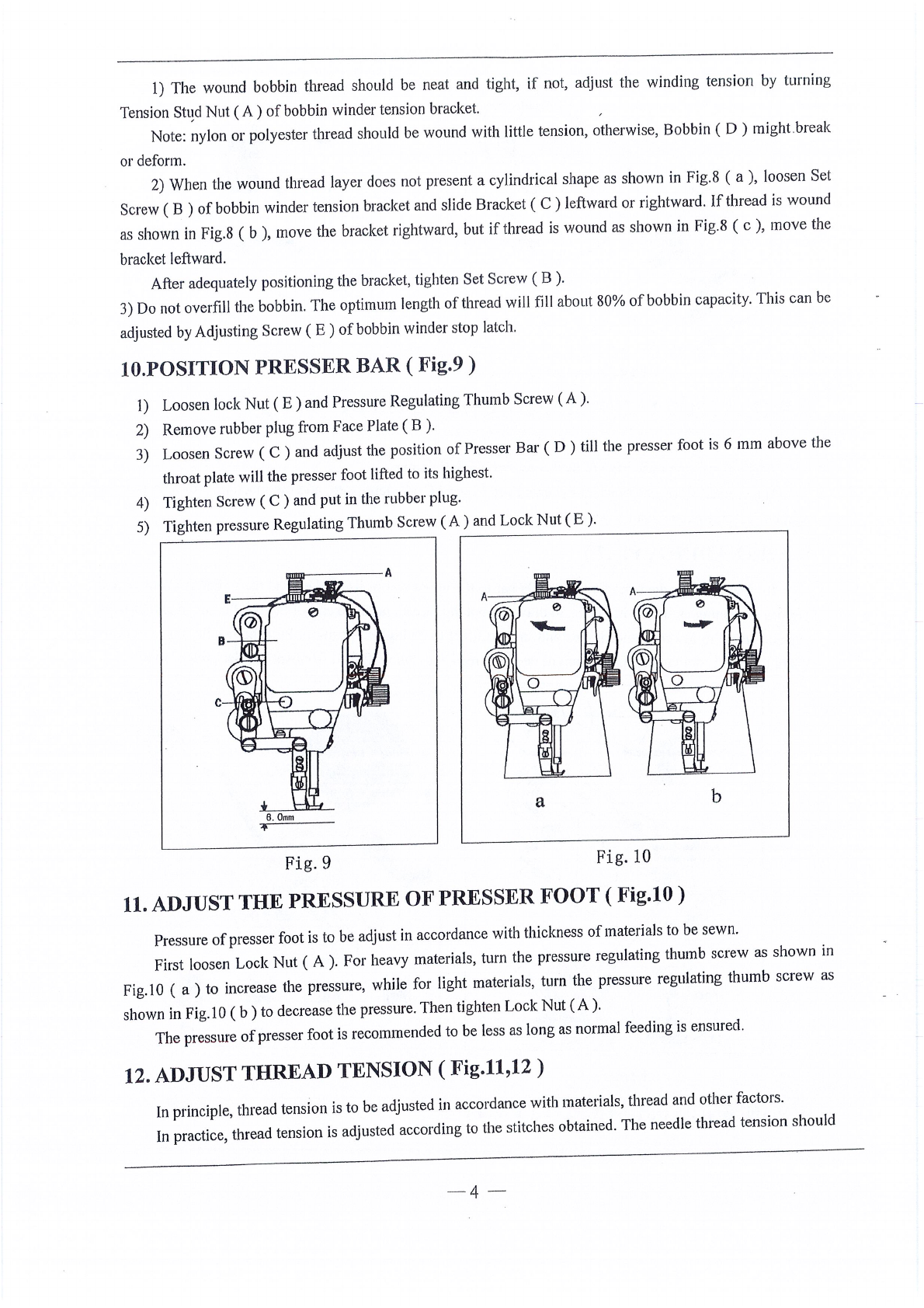
10.POSITION PRESSER BAR (
Fig.9)
1)
Loosen lock
Nut
(
E)
and Pressure Regulating Thumb Screw
(A).
2) Remove rubber plug from Face Plate ( B
).
3) Loosen Screw (
C)
and adjust the position
of
Presser
Bar
(
D)
till the presser foot
is
6 mm above the
throat plate will the presser foot lifted to its highest.
4) Tighten Screw (
C)
and put
in
the rubber plug.
5) Tighten pressure Regulating Thumb Screw
(A)
and Lock Nut ( E
).
a b
Fig.9 Fig.
10
11.
ADJUST THE PRESSURE OF PRESSER FOOT (
Fig.10)
Pressure
of
presser foot is to be adjust
in
accordance with thickness
of
materials to be sewn.
First loosen Lock Nut ( A
).
For heavy materials, turn the pressure regulating thumb screw as shown
in
Fig.
IO
( a ) to increase the pressure, while for light materials, turn the pressure regulating thumb screw as
shown in Fig.
IO
(
b)
to decrease the pressure. Then tighten Lock Nut
(A).
The pressure
of
presser foot is recommended to be less
as
long as normal feeding
is
ensured.
12. ADJUST THREAD TENSION ( Fig.11,12 )
In
principle, thread tension
is
to be adjusted
in
accordance with materials, thread and other factors.
In
practice, thread tension is adjusted according to the stitches obtained. The needle thread tension should
-4
From the library of Superior Sewing Machine & Supply LLC - www.supsew.com

be adjusted with reference to the bobbin thread tension. Turn Tension Spring Regulating Screw (
A)
of
bobbin
case clockwise for more tension, or turn the screw counter-clockV{ise for less tension.
It
is common practice to test the bobbin test the bobbin thread tension as shown
in
Fig.12 . Hold the end
of
the thread from delivery eye.
If
the bobbin case is falling slowly, the proper tension
is
obtained. The needle
thread tension can be adjusted by setting ( 1 ) the take-up spring tension. ( 2 ) the thread take-up spring stroke
and ( 3 ) tension spring. All these adjustments will be described
in
the following.
Fig.
11
Fig.
12
13.
ADJUST THREAD TAKE-UP SPRING ( Fig.13,14)
Fig.
13
Fig.
14
l)
Adjusting the thread take-up spring tension
Loosen Set Screw
(A),
turn Tension Stud (
B)
clockwise to increase the spring tension,
or
turn the stud
counter-clockwise to decrease the spring tension. After the adjustment,
be
sure to tighten Set Screw
(A)
. The
thread take-up spring tension should be about 30g. To Attain this. First loosen Set Screw ( A ), turn Tension
Stud ( B ) counter-clockwise to decrease the tension
of
Thread Take-
up
Spring ( C ) to zero, then turn Tension
Stud (
8)
clockwise until Spring (
C)
comes to the notch
of
thread tension regulating bushing, and again turn
Tension Stud ( B ) halfway back ( counterclockwise ) After the adjustment. Tighten Set Screw
(A).
2) Adjusting the thread take-up spring stroke
Loosen Set Screw ( B ), turn Stud ( C ) clockwise to increase the .stroke
or
turn Stud ( C )
counter-clockwise to decrease the stroke.After the adjustment, tighten Set Screw ( B
).
Before leaving the factory, the thread take-up spring has properly been adjusted. Readjustment
is
needed only
in
the case
of
special material or special thread.
-5-
From the library of Superior Sewing Machine & Supply LLC - www.supsew.com

14. ADJUST THREAD GUIDE AND THREAD TENSION (
Fig.15,16)
The position
of
the thread guide affects stitch tightness and therefore must be adjusted according to
sewing materials and sewing conditions.
FiglS shows different stitch forms. Normal stitch form should
be
as
shown
in
Fig.
IS
(
a).
When abnormal stitches cause puckering
and thread break-age, the tension
of
needle thread and bobbin
thread must
be
adjusted accordingly.
I
2
3
Thread guide position Leftward Center Rightward
Material weight Heavy Medium Light
Fig.
15
a
b
C
d
e
I)
In
case needle thread tension
is
too strong or bobbin thread tension
is
too weak, as shown in Fig.lS ( b ),
turn the thumb nut counterclockwise to decrease the needle thread tension, or tighten the tension spring
regulating screw
of
bobbin case to increase the bobbin thread tension ( See Fig.16 )
Fig.
16
Fig.
17
2) In case needle thread tension
is
too weak
or
bobbin thread tension
is
too strong, as shown in Fig.
15
( c
),
turn the thumb nut clockwise to increase the needle thread tension, or loosen the tension spring regulating
screw
of
bobbin case to decrease the bobbin thread tension.
3)
In
case
of
the stitch forms as shown
in
Fig.1 S ( d ) and ( e ), adjustments can be made with reference to the
above means.
15. TIME NEEDLE TO ROTATING HOOK ( Fig.17,18,19,20 )
A. Adjusting the needle position ( See Fig.17 )
1)
Turn balance wheel by hand to bringNeedle Bar (
C)
to the lowest position
of
its stroke.
2) Remove rubber plug from Face Plate
(A)
.
3) Loosen Set Screw ( B )
of
needle bar adaptor.
4) Move Needle Bar (
C)
vertically to adjust needle timing.
5) After the adjustment, tighten Set Screw ( 8 ) and put
in
the rubber plug. The standard needle timing ( See
Fig.18 )
is
to align Timing Mark ( B ) on the needle bar and the bottom
of
Needle Bar Bushing ( A ) and
- 6
·-
From the library of Superior Sewing Machine & Supply LLC - www.supsew.com

meanwhile align the Inner Surface (
E)
of
the hook and the center
of
Needle Eye ( D ) when the needle bar
gets down to its lowest position.
Fig.
18
B.
Adjusting the hook point timing
0.
05mm
Fig.
19
Timing
of
needle motion to rotating
hook
motion has a great effect on sewing performance. The standard
hook point timing ( See Fig.20 )
is
to align Hook Point ( D ) and Needle Centerline ( C ) when Needle
Bar
(
B)
is
lifted by 2.2mm from the lower end
of
its stroke. Besides, Hook Point (
D)
should be 1.0-1 .Smm above
the upper end
of
needle eye ( E
).
When adjusting the hook point timing, also notice that the clearance between the bottom
of
needle notch
and Hook Point (
C)
should be approx. 0.05mm ( See Fig.19 )
Fig.20 Fig.21
16.
REPLACE ROTATING
HOOK
( Fig.21 )
1)
Lift needle bar to the highest position
of
its stroke.
2)
Remove throat plate, take down needle and bobbin case.
3)
Loosen Screw (
C)
of
hook positioner and take down Hook Positioner
(A).
4)
Loosen two Screws (
D)
of
rotating hook.
5)
Turn balance wheel to raise feed bar to its highest position, then take down the rotating hook
by
turning
it
away from feed bar.
6)
Installing the hook can be done in reverse sequence. Note that Needle ( B ) and the convex surface
of
Hook Positioner
(A)
should align with a clearance
of
0.5-0.7mm between them.
17.
ADJUST THE HEIGHT
OF
FEED DOG ( Fig.22,23 )
I)
Turn balance wheel until feed dog is lifted to its highest position from throat plate surface.
2)
Loosen Screw
(A)
of
feed lifting rock shaft crank right ( See
Fig.22,b)
-7-
From the library of Superior Sewing Machine & Supply LLC - www.supsew.com

3) Move Feed Bar ( B ) in the direction shown by the arrow in Fig22 ( a ) to adjust the he
ight
of
the feed
dog. The standard height
of
feed ,dog
is
that the top
of
feed dog
is
1mm
above
Throat
Plate S,urface
( B ).
4) After the adjustment, be sure to tighten Screw
(A)
.
a
b
Fig.
22
Fig.
23
18.
ADJUST THE POSITION OF FEED DOG ( Fig.24,25)
The standard position
of
feed dog
is
that the clearance between the front end
of
the
throat
plate slot and
the first tooth
of
the fully advanced feed dog
is
Imm,
as
shown in Fig.24.
1)
Fully advance the feed
dog
toward the front end
of
the throat plate slot.
2) Loosen Feed Rock Shaft
Crank
Screw
(A).
See Fig.25 ( b ).
3)
Move
Feed Bar ( B ) in the direction shown by the arrow in Fig. 25
(a)
to adjust the feed
dog
position.
4) After the adjustment, be sure to tighten Screw
(A)
.
.--
-
-----{A
a
b
Fig.24 Fig.25
19. TIME FEED MOTION TO NEEDLE MOTION ( Fig.26,27,28)
The standard timing
of
feed motion to needle
motion
is
that the top
of
feed
Dog
( C )
is
flush with
Throat Plate Surface ( B )
when
the point
of
Needle
(A)
reaches Throat Plate Surface ( B ). See Fig.26 .
Fig.26
If
feed motion•
is
not timed to needle motion, adjust as follows ( See Figs.27 and 28
).
I)
Remove
Ann
Side
Cover
.
2) Loosen Set Screws
(A)
and (
D)
of
feed and feed lifting eccentric.
3) Hold Feed and Feed Lifting Eccentric ( B ) and turn Balance Wheel ( E ) slowly until the upper
edge
of
Arm Shaft Oil Hole ( C ) aligns with the lower edge
of
Reference
Hole
( G )
of
feed
and feed lifting
·-
8-
From the library of Superior Sewing Machine & Supply LLC - www.supsew.com

eccentric.
4) Leave a clearance
of
0)-0.Smm
between Feed and Feed Lifting Eccentric ( B ) and J;:ccentric
Sleeve
( H ), then tighten Set Screws
(A)
and ( D ).
Fig.27 Fig.28
20. ADJUST OPENING TIME OFTHE TENSION DISCS ( Fig.29 )
within the presser foot lift range
of
2-7mm opening time
of
the tension discs can
be
adjusted as follows:
I)
Remove
the rubber
plug
from the back
of
arm and loosen Screw
(A)
of
knee
Iifter lever ( left
).
2)
Move
the tension releasing cam leftward for earlier opening
or
rightward for later opening. It will
facilitate
the
adjustment to put
under
the presser foot a block as thick
as
the presser foot lift.
3) After the adjustment, fully tighten Screw
(A).
L.....- ~
,,,..
I --
-~
1
•-·
·
--
-'
Plug hole J
1 /
_.....,..
i I
(
,,,,--
Rightward
A
I
I
. I
I
I /
,;:;--
..,.,..,,,,.,.
4 ~
I ,,.- -
I/
I
C,,.
I
I
..
',
-- -
/
/
Cam
'"°l::
~
Presser feet
Fig.29
21. LUBRICATION ADJUSTMENT (Fig.JO)
A. Adjusting oil pump.
A
Fig.30
In ordinary operation, adjustment
is
not required for the oil pump.
If
oil splashing does
not
occur in the
oil
check
window
when
the machine runs at a low, speed ( approx.2000spm ), reduce the clearance
of
the
by-pass hole.
8 .Adjusting the lubrication
of
rotating hook.
The
lubrication
of
the rotating hook can be adjusted by Oil Adjusting Screw
(A)
as follows:
1) Turn Oil Adjusting Screw ( A ) clockwise to increase oil and turn Oil Adjusting Screw ( A )
counterclockwise to decrease oil.
2) Oil Adjusting
Screw
( A ) adjusts oil amount within 5 turns. When Oil Adjusting
Screw
( A )
is
fully
-9-
From the library of Superior Sewing Machine & Supply LLC - www.supsew.com

tightened, oil amount
is
maximum.
3) Readjustment depends on temperature, sewing speed and the like. In practice,
oil,
amount can
be
judged
as
follows: remove the throat plate and place a piece
of
paper
on
instead, run the machine for about 20 seconds,
then check the oil splashed on the paper.
22.INSTALLING OFTHE NEDDLE PLATE ( Fig.31)
To
attach the needle plate, bring the cloth-cutting knife to its lowest position, and gradually tighten the
two set screws alternately while lightly pressing the needle plate onto the cloth-cutting knife.
a
b
Fig.
31
Fig.
32
23. CLOTH CUTTINGKNIFE ( Fig.32,33)
I) Operation
of
the cloth cutting knife
-
(I)
To
actuate the cloth-cutting knife, press down
kni~e
setting plate l.
(2)
To
stop the cloth-cutting knife and reset the
machine to the normal lockstitching mode, pull
knob 2 in the direction
of
the arrow.
2) Attaching the cloth cutting knife
(I)
Raise or lower the cloth-cutting knife so that
section A
of
the cloth-cutting knife
is
positioned 0-0.5 mm below the top face
of
the
needle plate when the knife
is
in
its lowest
position.
(2) Loosen two knife set screws
1,
and replace the
cloth-cutting knife.
3) Changing the cutting width
(1) The needle plate decides the cutting width.
whenthe needle plate
is
replaced, loosen knife
Fig.33
0-0.5=
guiding shaft set screw 1 so that proper parallelism
is
obtained and the sharpness
of
the knife
blade
is
increased
as
shown
in
the figure.
(2) When the position
of
the knife
is
ch~mged
in accordance with the change
of
the needle plate size,
loosen set screw 2, and position the knife so that the blade
of
the needle plate comes
in
contact
with the knife blade. Then tighten set screw
2.
(3)
For
the standard machine, 8.0 mm wide needle plate is installed at the time
of
delivery.
-10-
From the library of Superior Sewing Machine & Supply LLC - www.supsew.com

24. REGULAR CLEANING ( Fig.34,35,36)
I) Cleaning feed dog ( See
Fig.34)
Remove the throat plate and clear offthe dust and lint between feed dog tooth slots.
Feed
dog
Feed
bar
Screen
Fig.34 Fig.35 Fig.36
2) Cleaning rotating hook ( See Fig 35 )
Swing out the machine head and clean the hook. Wipe the bobbin case with soft cloth.
3) Cleaning oil pump, screen ( See
Fig.36)
Swing out the machine head and clear
off
the dust and dirt on oil pump screen.
-11
-- -
From the library of Superior Sewing Machine & Supply LLC - www.supsew.com

A.ARM
BED
AND
ITS
ACCESSORIES
5
6
9-
39
57
56
"
a(
38
1sJ
0
16
17
18
19
2
-
12
--
12
11
13
14
45
38
II
r-----44
From the library of Superior Sewing Machine & Supply LLC - www.supsew.com

A.ARM BED AND ITS ACCESSORIES
Fig.
Pa
rt
No. Description Pcs. Remarks
No.
,
AO
!
HM30B47101
A
rm
1
A02
HM31B08001
Trade
mark
pl
ate
1
A03
H924025050
rivet
2 GB/f827 2.5x5
A04
H005008060
Spring
washer
2
GB/T93
6
A05
H2
100B2110
Face
plate
I
A06
HA306B0674
Rubber
plug
(
cp
1
1.8
) 3
A07
HA607B0671
Thread
guide
on
face
pl
ate
I
A08
HA106B0676
Th
read
guide screw I SM9/64(40)x6
A09
HA700B2030
Face
pl
ate
screw 2 SM! 1/64(40)x20
AID H2
100B2070
Arm
sidecover(left) 1
A
ll
H2100B2080
Arm
sidecover(right) I
Al2
H2100B2090
Gasket
for
arm
side cover 1
A13
HA300B2170
Set
screw
8
Al4
H1210B0671
Check
window
I
AI5
HA112B0691
Screw
type
tension stud· 1
SM
11
/64(40)x 16
Al6
HA112B0692
Spring
for
pre-tension 1
Al7
HA112B0693
Disc
for
pre-
tension 2
Al8
HA112B0694
Spacer
for
pre-tension I
A19
H007013030
Stop
ring
I
GB/T896
3
A20
HA112B0695
Pre-tensi
on
th
read
guide
1
A21
HA100B2100
Th
ree-hp
le thread
gu
i
de
1
A22
HA100B2110
Set
screw
1
SMI 1/64(40)x5
A23
HA1
1
5B0701
Th
read
tension
st
ud I SM1/4(40)x
J7
A24
HA310B0701
Oil
thumb
nut 1
A25
HA505B0671
Th
read
tension spring 1
A26
HA310B0702
Th
read
tens
i
on
releasing disc I
A27
HA310B0705
Thread
tension
di
sc 2
A28
HA505B0672
Thread
t
ake-up
spring 1
A29
HA310B0703
Thread
tension regulating bushing 1
A30
HA115B0708
Set
screw
I SM9/64(40)x6
A31
HA115B0709
Thread
tension releasing pin 1
A32
HA115B7010
Stop
di
sc
I
A33
HA115B7011
Rubber
ring
I
A34
HA300B2080
Set
screw
1
SM!
5/64(28)x6
A35
HA600B2050
Thread
guide
at
arm
center 1
A36
H
A30
0
B2090
Rubber pl
ug
(cp8
.
8)
2
A37
HA300B2100
Rubber plug (
cp27
) I
A38
HA300B2110
Red
rubber pl
ug
(cp5.7)
2
A39
HM31B37101
Need
le plate I
A40
HA300B2190
Need
le plate screw 6
SM!
1/64(40)
x4.5
A4
1
H6812B8001
Slide pl
ate
I
A42
HA324B0711
Slide pl
ate
spring I
A43
HA124B0713
Screw
2 SM3/32(56)x2.2
-13
-
From the library of Superior Sewing Machine & Supply LLC - www.supsew.com

A.ARM
BED
AND
ITS
ACCESSORIES
Fig.
Part
No
. Description
Pcs.
Remarks
No.
A44
HA100B2220
Leg
3
A45
HA30780673
Rubber
plug
2
A46
HM31887101
Chip
funnel
I
A47
HM31868001
Chip
guide
plate
mounting
plate
I
A48
HM31B78001
Chip
guide
plate
I
A49
H5727B8001
Screw
2
SM
1/8(
44
)/3
.4
AS0
HM32B47101
Single
needle
binders
I
AS!
HM32B38001
Single
needle
binders
mounting
plate
I
AS2
H3200I2030
Washer
2
AS3
H415040060
Screw
2
M4x6
AS4
·
H7339C7101
Mounting
plate
comp
l
ete
I
ASS
H7342C8001
Screw
2
A56
H2100B2130
Fe
lt
I
A57
H210012050
Shelter platr
I
A58
HA100C2040
Screw
I
SMl 1/64(40)/5
A59
HA500C2060
Thread
guide
I
A60
HA500C2070
Set
screw
I SM9/64(40)x5
-
14
-
From the library of Superior Sewing Machine & Supply LLC - www.supsew.com

B.SEWING MECHANISM
27
30
32
29
45
41
O
'
I
8 7
24 25
\
11
12
23
,:,)-22
20
21
69~
70
•·
····
r\1 54
55
58
71
72
68
-
15
--
0
42
57
56
62
\
·'
37
73
74 75
From the library of Superior Sewing Machine & Supply LLC - www.supsew.com

B.SEWING
MECHANISM
Fig. Part No. Description Pcs.
No. Remarks
,
801
H11111Cl04 Therad take-up
lever
1
B02
H11112Cl04 Thread take-up
lever
link
I
B03
HA104C0653
Hinge
pin
I
804
HA504C0651
Thread
take
-
up
crank
1
B05
HA104C0656
Set
screw
( left-handed ) I SM9/64(
40)
x7
806
HA304C0653
Needle
bar
link I
807
HA104C0658
Needle
bar
adaptor I
B08
HA106B0676
Screw
I
SM9/64(40)x6
809
HA100C2020
Set
screw
I SM15/64(28)x!0
810
HD90C68001
Needle
bar
crank
1
811
HA307C0662
Set
screw
2
SM
l/4(40)x6
812
HA100C2060
Set
screw
1 SM9/32(28)x
13
813
HA100C2070
Set
screw
1 SM9/32/(28)x
14
814
HA100C2080
Need
le
bar
bush
i
ng
(upper) I
815
HA100C2100
Fe
lt plug 1
8 16
HA300C2050
Red
rubber
plug
(
q,8.8
) 1
817
HA804B0652
Needle
bar
bushing (lower) I
819
HD90C88001
Needle
bar
1
820
HD90C98001
Thread
guide
for
needle
bar
I
821
Needle 1 DPxl7
#22
822
HA100C2170
Needle
clamp
screw
I SM1/8(44)x4.5
823
HA100C2180
Guide
for
slide
block
I
824
HA100C2190
Set
screw 2
SM!
l/64(40)x8
825
HA100C2200
Slide bl
ock
I
826
HD90D58001
Arm
shaft I
827
HA104D0652
Ru
b
ber
plug (
cIJ7.4
xIO) I
828
HA
1
08G0661
Collar
for
. I
B29
HA105D0662
Set
screw
2
SMl/4(40)x4
830
H6507D8001
Arm
shaft bushing(left) I
831
HA100D2040
Arin
shaft bushing(middl
e)
1
832
HA100C2020
Set
screw 1
SM
I5/64(28)x I0
833
HA300D2020
Arvn
shaft bushing(right) I
B34
H
A306D0066
Oil
seal
I
835
H2000C2040
Balan
ce
wheel
1
836 HA
110D0672
Set
screw
2
SM
l5/64(28)x
12
837
HA100D2080
Screw
1 SM! l/32(28)x!0
838
H11211D105
Feed
and
feed
lifting eccentric 1
839
HA3411D308
Set
screw 2
SM
l5/54(28)x7
840
HA34
1
1D208
Eccentric sleeve I
841
HA112D3012
Retaining
ring
I
842
HA112D3013
Crank
rod
for
feed
lifting
rock
shaft I
843
HA504D0651
Feed
forked
connection I
B44
H210
0
D2010
Verticalshaft I
-16-
From the library of Superior Sewing Machine & Supply LLC - www.supsew.com

B.SEWING MECHANISM
Fig. Part No. Description Pcs. Remarks
No. ,
B45
HA113D2112
Bevel
gea
r
for
arm
shaft I
B46
HA113D2122
Bevel
gea
r
for
vetiicalshaft( u
pper
)
I
B47
H
A108C0663
Set
screw
8 SMl/4(40)x7
B48
HA113D2212
Bevel
gear
for
h
ook
sh
aft
I
B49
HA113D2222
Bevel gear
for
verticalshaft(
lower
)
I
B50
HA100D2110
Vetiical shaft bushing( upper)
I
B51
HA600D2010
Vertical shaft bushing( lower)
I
B52
HA100C2020
Set
screw
2 SMl5/64(28)x I0
B53
HA904E0651
Rotating hook shaft 1
B54
HA1111El04
Fi
lter
screw
1 SM3/l 6(32)x9
B55
HA1111E204
Fi
lter 1
B56
HA305E0661
Collar
for
hook
shaft 1
B57
HA305E0662
Set
screw
2 SMl5/64(28)x4
B58
HA106E0071
Oil
seal
for
rotating
hook
sh
aft
1
B59
HA100E2040
Hook shaft bushing ( left )
I
B60
HA100E2050
Oil
adjusting
screw
1
SM! 1/64(40)x28.5
B61
HA100E2060
Spr
i
ng
for
oi
l adjuster
I
862
HA311E0671
Hook
shaft bushing ( right )
I
B63
HA
11
0E0672
Oi
l
pipe
for
hook sh
aft
bu
shing
I
B64
HA30
0
E2100
Plunger
I
B65
HA300E2110
Plunger
spr
i
ng
I
B66
HA600E2020
Gu
ide
pl
ate
I
B67
HA104F0654
Screw
I
SM
l5/64(28)x I0
868 Hll05E0065 Rotating hook
comp
l
ete
I
869
HM30E48001
Rotating
hook
positioner 1
B70
HA100E2150
Screw
I
SM
1
1/64(
40)x
I0
B7
1
HA608E0067
Bo
bbin
case
I
872 H
ll
0OE20
10
Bo
b
bi
n 1
873
HA7
1
2N6912
Screw
2
SM
l/8(44)x7
B74
H005001040
Washer
2
!ff~l4(t/Jr~)
875
H2100B2100
Arm
sidecover baffle
I
-
17
-
From the library of Superior Sewing Machine & Supply LLC - www.supsew.com

C.STITCH
REGULATOR
MECHANISM
18
-
From the library of Superior Sewing Machine & Supply LLC - www.supsew.com
Other Global Industrial Equipment manuals

Global
Global WF 1767-70 Series Parts list manual

Global
Global BEAT-MV User manual

Global
Global ZZ 9567-75 User manual

Global
Global SV 550 User manual

Global
Global ZZ 1560 Series Troubleshooting guide

Global
Global 3995DD Series Product guide

Global
Global 316088 User manual

Global
Global WF3955-45DD Series Product guide

Global
Global SM 7830 AL Parts list manual

Global
Global WF 1767-AUT Parts list manual