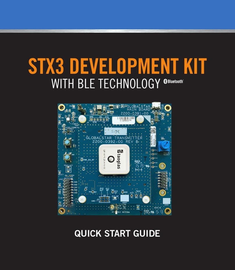
Globalstar ST150M User manual

1
ST150M
Development Kit
Quick Start Guide
9150-0151-01 R-2

1 2
• Analog Adjust potentiometer
• Expansion header
• Source code via GitHub with application library, hardware schematics, and more
• Mobile App available for iOS and AndroidOpen your VAR registration and
introduction email received from: message-noreply@globalstar.com.
CONTENTS OF ST150M DEV KIT WITH BLE PACKAGE
KEY FEATURES
• ST150M Dev Kit
• STX & GPS Antenna Arduino Uno shield
• This Quick Start Guide
• 2 – Micro USB cables
• 2 – u. to u. coaxial cables
• 1 – USB wall transformer
• Globalstar Smart Data Satellite Modem Module (ST150M)
• nRF52840 ash-based Bluetooth®low energy, ANT/ANT+TM SoC solution
(https://infocenter.nordicsemi.com/topic/struct_nrf52/struct/nrf52840.html)
• Globalstar Satellite ASIC transmitter
• GPS and 3-axis accelerometer
• 2.4GHz Chip Antenna for Bluetooth®
• Multiple Interfacing Options: BLE, USB, UART
• BLE SmartOne Sensor Service
• User Controllable LEDs and button
ACTIVATING YOUR DEV KIT
The ST150M Development Kit is the fastest way to become familiar with the Globalstar
Enablement Suites Unied API utilized to support your development. The Arduino Uno shield
support allows you to quickly integrate with an expansive variety of hardware solutions.
Globalstar’s existing BLE solution is supported and enhanced with additional security options.
By taking advantage of the Unied API and application libraries, you can quickly be
generating Smart Data over the Globalstar Satellite Network. The ST150M also supports all
our existing message types in addition to new sub-message types.
An accompanying mobile app (iOS or Android) allows users to issue commands to
interface with the ST150M directly via the nRF52840 BLE SoC. Through a mobile app or
serial console, users may send user-dened custom data via the ST150 module through the
Globalstar Satellite Network.
The ST150M Development Kit comes with 60 days of pre-authorized satellite usage time.
The Activation form should be submitted prior to ordering this kit, but if changes are
required, please contact your Regional Sales Manager.
IMPORTANT NOTES:
The power needed for ST150M transmissions will exceed the supply current
available from typical USB ports on your laptop or PC. Conrm your USB can
source 500 ma of current to power the Dev Kit. If utilizing additional Arduino
Uno shields, the current requirements of each shield must be accounted for.
A current source capable of supplying 1 A or more is recommended.
The UID (Unique Identier) of your ST150M Dev Kit is located on the module. It
is 12 digits and listed on the top le-hand side of the label axed to the ST150M.
The user should activate the UID associated with the Dev Kit prior to
transmitting any messages. In this process, the routing is established for
messaging through the Globalstar Satellite Network and the details related
to the activation of the 60-day trial period. Aer 60 days, renewal is required
with payment for continued satellite network service.
The ST150M Dev Kit must have a clear view of the sky to communicate on the
Globalstar Satellite Network.

3 4
HARDWARE SETUP
Remove the ST150M Dev Kit from the electrostatic safe bag.
Conrm or place the jumper on USB 5V header pins, jumper block J5.
NOTE: No jumper should be on the LINE IN header pins
Conrm or place the jumper on DC_INPUT_EN header pins, jumper block J5.
Locate Dev Kit Arduino shield Antenna PCB:
• Install one of the u. antenna cables to the GPS u. connector on the shield.
• Install the other end of the GPS cable to the GPS RX u. connector on the dev kit.
• Install a second u. antenna cable to the STX u. connector on the shield.
• Install the other end of the STX cable to the SAT TX u. connector on the dev kit.
Install the Dev Kit Arduino shield Antenna PCB onto the Dev kit board. Mate to
Arduino Rev 3 shield header (connector P17) as illustrated in the “Dev Kit Board with
Antenna Shield” image.
Connect a micro USB cable to the USB DC Input connection of the Dev Kit board to
USB supply having a current capability of 1 A.
• The red DC_IN LED should now be active/illuminated.
Switching the ON/OFF switch to ON position will activate the 3.3 V regulator and
provide power to the ST150M.
• The green 3.3 V LED should now be active/illuminated.
Using nRF Connect or the ST150 conguration application on either iOS or Android,
you should see the unit advertising its Bluetooth®id.
Utilize the phone application to generate a custom message. Details in the
following section.
DEV KIT BOARD AND CONNECTORS
DEV KIT BOARD WITH ANTENNA SHIELD
J5: DC
INPUT EN &
SELECT
ON/OFF
SWITCH
BLE
ANT
NFC
CONN
GEO
PERIPHERALS
ASIC PROGRAM/
DEBUG
nRF52x
PROGRAM/DEBUG
CLIENT USB
CONN
nRF RESET
STX OUTPUT
GPS INPUT
LINE DC
INPUT
USB DC
INPUT
CURRENT
SHUNT
ST150M
1
2
3
4
5
6
7
8
9

5 6
MOBILE APPLICATION SETUP
1. With the ST150M Dev Kit powered, you can now launch the iOS
or Android phone application to scan over Bluetooth®for the
UID associated with your board. Download the Globalstar “ST
Conguration Tool” application from either the Apple Store or
Android (Google Play) Store.
2. Once opened, the app will ask you to login with your username
and password. These are the same credentials that you used for the IoT MyAccount.
Log in and you will automatically scan for nearby ST Devices using BLE. Conrm that
your Dev Kit’s UID is displayed in the scan list.
3. Before connecting to a device, enable the diagnostic menu by performing the
following:
• Tap the Settings Icon .
• Under the “SUPPORT” section, tap the Version number 10 times.
• Scroll down and select “Show Diagnostics”.

7 8
4. Select your UID, and the App will oer the Connect button. Push the Connect button
and you will be taken to the Device Dashboard.
5. Here you are viewing the details as identied on the bottom menu bar. Also displayed
are the Device Conguration, History, and Update Firmware controls. In addition,
on the top menu bar, you can go to the device’s diagnostics screen, and access the
applications setup menu.
6. Tap the Diagnostics Icon .
7. Using the Command eld, you can enter commands to be processed by the ST150M.
NOTE: Only 0-9 and A-F are valid entries into the data eld. Use this for the following
example.

9 10
Please reference the table for a subset of available commands.
NOTE: The commands provided below are included only as examples. Please refer to the
ST150M User Manual and Unied API for a full description of all commands.
You may enter the commands exactly as described in the table as the interface allows you
to exclude the “AT+” prex. It is also not case sensitive.
COMMAND DESCRIPTION
CGSN? Queries ESN
GUID? Queries UID
TRACK? Queries the Track conguration
QABORTALL Aborts all remaining bursts that are ready to be transmitted
QCNT? Queries number of queued items
CFGVER? Queries the Conguration version
CGMR? Queries the device soware revision information
DHSTATUS? Queries the health check parameters
MCUTEMP? Queries the onboard temperature sensor in the nRF840 MCU
TXTEMP? Queries the onboard temperature sensor in the ASIC
GPSSTAT? Queried the status of the GPS
GPSPOS? Queries the current GPS position
ACCOSTATE? Queries the match state of the accelerometer
PWRSTATE? Queries the current power state mode
UART2PROP Queries UART2 conguration
GPIOLIST=0 Get a list of all GPIO
USING THE UART
To use the UART, an application capable of TTY communication over TTL UART interface
should be downloaded. The examples in this guide will reference PuTTY on Windows 10,
which can be downloaded via this link: https://www.putty.org
While your ST150M Dev Kit is turned o apply leads TTL RX to PO. 24, TX to PO. 16, and GND
to GND. Turn on the Dev Kit and using your serial port at 9600 baud, 8 data bits, 1 stop bit, No
parity, Flow XON/XOFF. You can now send AT commands to your dev kit via the UART.
The following example is utilizing a USB TTL device plugged into a PC running Windows.
1. Validate that the ST150M Dev Kit is recognized as a serial COM port by the Windows
PC by opening the Windows Device Manager utility and observing the listing under
the Ports (COM & LPT) devices. The ST150M Dev Kit will show up as “USB Serial
Port (COMxx)” where xx is the communications port number. As highlighted in the
example below, the ST150M Dev Kit is on communications port COM9.
2. Open PuTTY and select “Serial” connection type. Enter the COMxx port for the
ST150M Dev Kit as the Serial line and congure the Speed (Baud) to 9600. Select
“Open” and a console window will open to the ST150M Dev Kit.

11 12
3. At this point, the console can be used for Read commands. However, unlike the ST
Conguration App, the UART is an unsecured interface. In this case, you must elevate
your authorization permission for an Execute command. The SECAUTH command
will have to be executed to elevate your permission level. This elevation will remain
persistent until the module is reset or powered o.
• The following will need to be executed to elevate your permission with the
default password “gst150”
• AT+SECAUTH=1,gst150
ADVANCED DEVELOPMENT AND CUSTOMIZATION
With the ST150M Development Kit connected and communicating, you can now begin
development and integration with your own design. This kit provides you with various
examples for interfacing applications and peripheral sensors with the ST150M. This
Development kit also has Arduino Uno Rev3 form factor connectors for you to connect to
other development boards and utilize your existing design.
For further explanation of how to get started with soware design and integration of the
ST150M with your design, please refer to the ST150M User Manual and the ST150M BLE
Soware Design guide.
Globalstar can provide Gerber les, hardware schematics and source code for all apps and
nRF52840 rmware via our GitHub repository. Login details and further instructions will
be provided in separate documents.
Please visit Globalstar.com/support for the latest version of the Quick Start Guide.
THIS QUICKSTART GUIDE IS SUBJECT TO CHANGE WITHOUT NOTICE
© 2022 Globalstar. All rights reserved.
All trademarks, service marks, trade names, trade dress, product names and logos appearing
in this Quick Start Guide are the property of their respective owners.
9150-0151-01 R-2
Other manuals for ST150M
1
Table of contents
Other Globalstar Microcontroller manuals