GMI PSD1004 User manual

PSD1004 - Intrinsically Safe 5 V Supply Module ISM0074-5
PSD1004
INSTRUCTION MANUAL
Intrinsically Safe
5 V Supply Module
DIN-Rail Model PSD1004

2 PSD1004 - Intrinsically Safe 5 V Supply Module G.M. International ISM0074-5
General Description: The single channel DIN Rail Intrinsically Safe Power Supply PSD1004, is an intrinsically safe module that can be installed in Hazardous Area zone 0, gas group
IIB, temperature classification T4. Powered at about 12 Vdc from the intrinsically safe associated apparatus PSD1001C supply module, it provides a stabilized 5 V, 160 mA supply with
500 V input/output isolation, short circuit and reverse input polarity protection, remote sensing capability and regulation.
Function: 1 channel I.S. power supply, provides input/output isolation and 5 V, 160 mA regulated voltage. Typical application is to power intrinsically safe circuits implementing digital
logic blocks, microcontroller operated peripherals like keyboards, encoders, logic solvers, LCD display units and transmitters.
Signalling LED: Power supply indication (green).
EMC: Fully compliant with CE marking applicable requirements.
Supply: from PSD1001C supply module (nominal 20.5 Vdc with 68.3 Ωseries resistance).
Isolation (Test Voltage): Input/Output 500 V.
Output:
Voltage: 5 Vdc ± 3 %.
Current: 0 to 160 mA.
Voltage regulation: ≤0.2 % for a 0 to 160 mA load change.
Output ripple: ≤20 mVrms.
Compatibility:
CE mark compliant, conforms to 94/9/EC Atex Directive and to 2004/108/CE EMC Directive.
Environmental conditions: Operating: temperature limits -20 to + 60 °C, relative humidity max 90 % non condensing, up to 35 °C.
Storage: temperature limits – 45 to + 80 °C.
Safety Description:
II 1 G EEx ia IIB T4 intrinsically safe apparatus.
Uo = 6.51 V, Po = 1760 mW at terminals 13-14-15-16.
Ui = 24.2 V, Ii = 363 mA, Pi = 1760 mW, Ci = 330 nF, Li = 0 nH at terminals 1-2/3-4. -20 °C ≤Ta ≤60 °C.
Approvals: DNV-2005-OSL-ATEX-0334X conforms to EN50014, EN50020, EN50284, IEC60079-0, IEC60079-11,
DNV and KR Type Approval Certificate for marine applications.
Mounting: T35 DIN Rail according to EN50022.
Weight: about 125 g.
Connection: by polarized plug-in disconnect screw terminal blocks to accomodate terminations up to 2.5 mm2.
Location: Hazardous Area Zone 0, Group IIB, Temperature Class T4 installation.
Protection class: IP 20.
Dimensions: Width 22.5 mm, Depth 99 mm, Height 114.5 mm.
Model: PSD1004
Technical Data
Ordering information
Characteristics
Front Panel and Features
Installation in Zone 0.
High output capability Power Supply for Hazardous Area equipment.
Short circuit proof stabilized output with remote sensing voltage regulation.
Rugged sealed construction suitable for installation in harsh environments.
Isolation Input/Output.
EMC Compatibility to EN61000-6-2, EN61000-6-4.
ATEX Certification.
Type Approval Certificate DNV and KR for marine applications.
High Reliability, SMD components.
Simplified installation using standard DIN Rail and plug-in terminal blocks.

3
PSD1004 - Intrinsically Safe 5 V Supply ModuleG.M. International ISM0074-5
Terminal block connections
Parameters Table
Must
be
Hazardous Area/
Hazardous Locations
Device Parameters
PSD1004 Associated
Apparatus Parameters
Uo / Voc Ui / Vmax
In the system safety analysis, always check the Hazardous Area/Hazardous Locations devices to conform with the related system documentation, if the device is Intrinsically Safe check
its suitability for the Hazardous Area/Hazardous Locations and gas group encountered and that its maximum allowable voltage, current, power (Ui/Vmax, Ii/Imax, Pi/Pi) are not exceeded
by the safety parameters (Uo/Voc, Io/Isc, Po/Po) indicated in this manual and enclosure side of the PSD1004 Intrinsically Safe Apparatus connected to it.
Io / Isc
≤
Ii/ Imax≤
Po / Po Pi/ Pi≤
When checking the power matching also consider the maximum operating temperature of the field device, check that added connecting cable and field device capacitance and
inductance do not exceed the limits (Co/Ca, Lo/La, Lo/Ro / La/Ra) given in the Associated Apparatus parameters for the effective gas group (see parameters on enclosure side).
Must
be
Hazardous Area/
Hazardous Locations
Device + Cable Parameters
PSD1004 Associated
Apparatus Parameters
Co / Ca Ci / Ci device + C cable
Lo / La
≥
Li / Li device + L cable≥
If the cable parameters are unknown, the following value may be used: Capacitance 60 pF per foot (180 pF per meter), Inductance 0.20 mH per foot (0.60 mH per meter).
Note that for the PSD1004 the system analysis must be performed for the input and also for the output connection.
Storage
If after an incoming inspection the unit is not installed directly on a system (parts for spare or expansion with long storage periods) it must be conveniently stocked. Stocking area
characteristics must comply with the following parameters:
Temperature –10 to +30 °C the – 40 to +80 °C in the data sheet is meant for limited periods, mainly to arrange for air transport.
Humidity 0 to 70% long period high humidity affects the package integrity and promotes corrosion of metal parts.
Vibration: no vibration should be perceivable in the stocking area to avoid loosening of parts or fatigue ruptures of components terminals.
Pollution: presence of pollutant or corrosive gases or vapors must be avoided to prevent corrosion of conductors and degradation of insulating surfaces.
Disposal (Waste Electrical and Electronic Equipment)
This marking shown on the products indicates that it should not be disposed with other wastes at the end of its working life. It may content hazardous substances for the health and the
environment, to prevent possible harm from uncontrolled waste disposal, please separate this equipment from other types of wastes and recycle it responsibly to promote the sustainable
reuse of material resources. Users should contact either the supplier or their local government office for details of where and how they can take this equipment for environmentally safe
recycling. This product should not be mixed with other commercial wastes for disposal.
Output + O
HAZARDOUS AREA SAFE AREA
Output + S
Output - S
Output - O
13
14
15
16
Positive terminal for terminal 13 of model PSD1001C
1
Negative terminal for terminal 14 of model PSD1001C
2
Positive terminal
3
Negative terminal
4

4 PSD1004 - Intrinsically Safe 5 V Supply Module G.M. International ISM0074-5
PSD1004 is an isolated Intrinsically Safe Power Supply Module installed into standard EN50022 T35 DIN Rail located in Safe Area / Non Hazardous Locations or
Zone 0, Zone 1, Zone 2 Hazardous Area, Gas Group IIB or IIA, Temperature Classification T4 (according to IEC/EN60079-11, EN50020) within the specified operating temperature limits
Tamb -20 to +60 °C, and connected to Associated Apparatus equipment with a maximum limit for Uo<Ui, Io<Ii and Po<Pi as specified in the data sheet.
PSD1004 must be installed, operated and maintained only by qualified personnel, in accordance to the relevant national/international installation standards
(e.g. IEC/EN60079-14 Electrical apparatus for explosive gas atmospheres - Part 14: Electrical installations in hazardous areas (other than mines), BS 5345 Pt4, VDE 165,
ANSI/ISA RP12.06.01 Installation of Intrinsically Safe System for Hazardous (Classified) Locations, National Electrical Code NEC ANSI/NFPA 70 Section 504 and 505,
Canadian Electrical Code CEC) following the established installation rules, particular care shall be given to segregation and clear identification of I.S. conductors from non I.S. ones.
Warning: substitution of components may impair Intrinsic Safety.
Failure to properly installation or use of the equipment may risk to damage the unit or severe personal injury.
The unit cannot be repaired by the end user and must be returned to the manufacturer or his authorized representative, any unauthorized modification must be avoided.
Warning
Operation
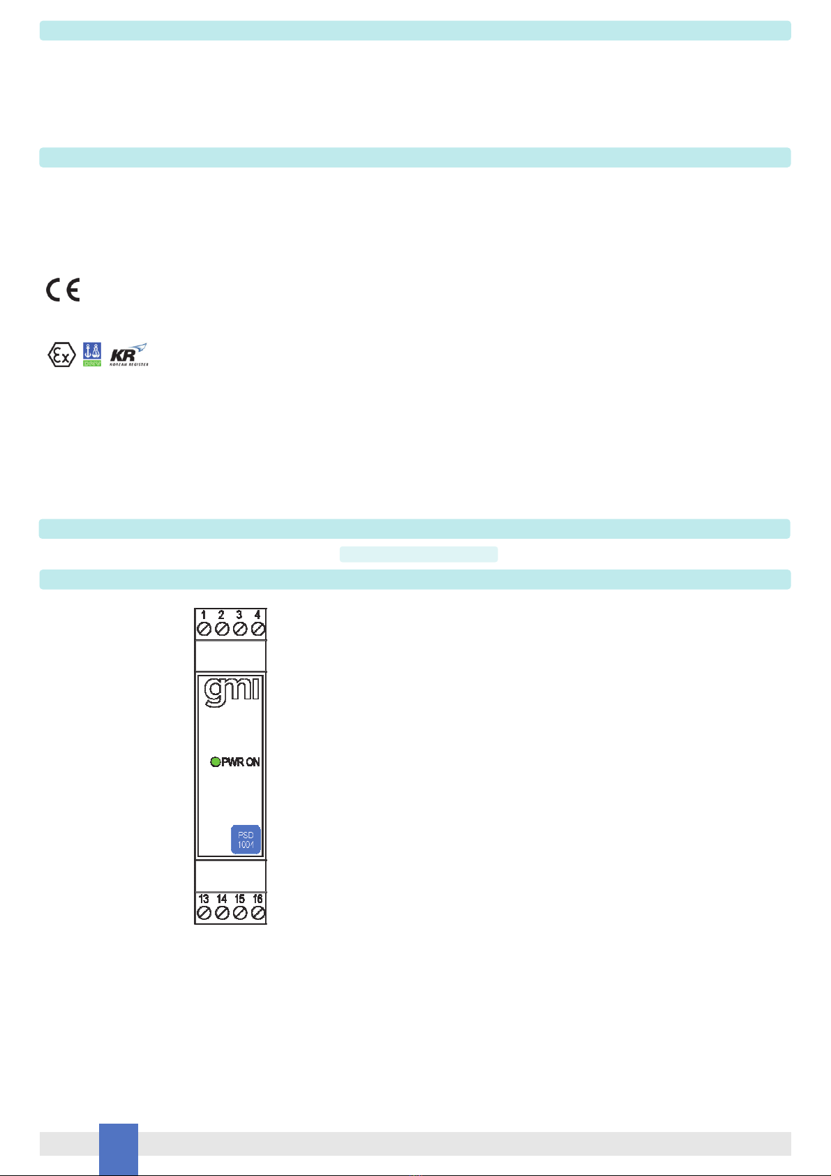
PSD1004 provides fully floating 5 VDC supply to drive Intrinsically Safe loads, typically transmitter or display unit located in Hazardous Area. PSD1004 has remote sensing capability to
compensate line resistance voltage drop-out, connect the sense terminals near the load at the output terminals for better performance and stabilization. If the line resistance is low,
connecting the sense terminals is not mandatory (the voltage stabilization is done internally to the module). Presence of supply power is displayed by a green signaling LED.
Installation
PSD1004 is an I.S. power supply housed in a plastic enclosure suitable for installation on T35 DIN Rail according to EN50022.
PSD1004 unit can be mounted with any orientation over the entire ambient temperature range, see section “Installation in Cabinet” and "Installation of Electronic Equipments in Cabinet"
Instruction Manual D1000 series for detailed instructions.
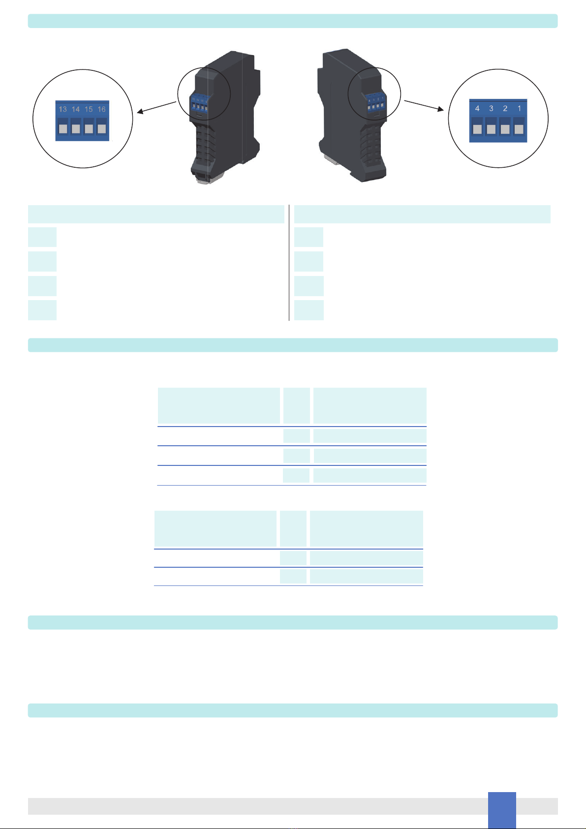
Electrical connection of conductors up to 2.5 mm² are accommodated by polarized plug-in removable screw terminal blocks which can be plugged in/out into a powered unit
without suffering or causing any damage.
The wiring cables have to be proportionate in base to the current and the length of the cable.
On the data sheet and enclosure side a block diagram identifies all connections.
Identify the function and location of each connection terminal using the wiring diagram on the corresponding data sheet, as an example:
Connect input power positive at terminal “1” or “3” and negative at terminal “2” or “4” (two terminals are provided for daisy chain connection if required to supply two PSD1004
with a single Associated Apparatus).
Connect positive output at terminal “13” and negative output at terminal “16”.
Connect sense terminal, if required, at terminal “14” positive and terminal “15” negative.
Note that junction point must be near as possible to the load.
Intrinsically Safe conductors must be identified and segregated from non I.S. and wired, in accordance to the relevant national or international installation standards
(e.g. IEC/EN60079-14 Electrical apparatus for explosive gas atmospheres - Part 14: Electrical installations in hazardous areas (other than mines), BS 5345 Pt4, VDE 165,
ANSI/ISA RP12.06.01 Installation of Intrinsically Safe System for Hazardous (Classified) Locations, National Electrical Code NEC ANSI/NFPA 70 Section 504 and 505,
Canadian Electrical Code CEC), make sure that conductors are well isolated from each other and do not produce any unintentional connection.
The enclosure provides, according to EN60529, an IP20 minimum degree of mechanical protection (or similar to NEMA Standard 250 type 1) for indoor installation, outdoor installation
requires an additional enclosure with higher degree of protection (i.e. IP54 to IP65 or NEMA type 12-13) consistent with the effective operating environment of the specific installation.
Units must be protected against dirt, dust, extreme mechanical (e.g. vibration, impact and shock) and thermal stress, and casual contacts.
If enclosure needs to be cleaned use only a cloth lightly moistened by a mixture of detergent in water.
Electrostatic Hazard: to avoid electrostatic hazard, the enclosure of D1014 must be cleaned only with a damp or antistatic cloth.
Any penetration of cleaning liquid must be avoided to prevent damage to the unit. Any unauthorized card modification must be avoided.
Start-up
Before powering the unit check that all wires are properly connected, particularly their polarity, also check that Intrinsically Safe conductors and cable trays are segregated (no direct
contacts with other non I.S. conductors) and identified either by color coding, preferably blue, or by marking. Check conductors for exposed wires that could touch each other causing
dangerous unwanted shorts. Turn on power, the “power on” green led must be lit, check the supply voltage generated by PSD1004 is 5 Vdc.
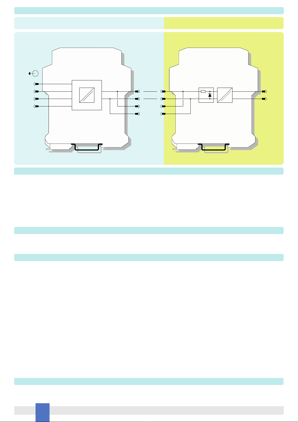
Function Diagram
MODEL PSD1001C
+ 13
- 14
3 +
4 - Supply
Out
=
=
+ 15
- 16
MODEL PSD1004
O + 13
S + 14 1 +
2 -
=
=
S - 15
O - 16 3 +
4 -
PSU1003
HAZARDOUS AREA ZONE 0, GROUP IIB T4 SAFE AREA, ZONE 2, GROUP IIC T4
Table of contents
Other GMI Power Supply manuals
Popular Power Supply manuals by other brands

TDK-Lambda
TDK-Lambda HFE2500-S1U instruction manual

BEL
BEL TCP3500-048G Series Installation instruction

Newcastle Systems
Newcastle Systems PowerSwap Nucleus MINI owner's manual

Puls
Puls CS5.241-C1 installation manual

Pulsar
Pulsar 276V/5A/2x17Ah/LCD manual

TDK-Lambda
TDK-Lambda GWS250 Series instruction manual