GMI PSD1220 User manual

PSD1220 & PSD1220-098 - SIL 3 Power Supply, 24Vdc, 20 A, Zone 2, DIN Rail Mounting G.M. International ISM0370-3
SIL 3 Power Supply PSD1220 and PSD1220-098
24Vdc, 20 A, Zone 2
DIN Rail Mounting
PSD1220 and PSD1220-098
INSTRUCTION MANUAL
G.M. International s.r.l.
20852 Villasanta MB Italy

PSD1220 & PSD1220-098 - SIL 3 Power Supply, 24Vdc, 20 A, Zone 2, DIN Rail Mounting G.M. International ISM0370-3
2
General Description:
The Power Supply types PSD1220 and PSD1220-098 are anodized aluminum unit.
The Power Supply provides 24Vdc, 20 A output. PSD1220 or PSD1220-098 unit can be paralleled, with load sharing circuits, which distribute current load equally to each power supply
to increase reliability and reduce internal power dissipation.
The Power Supply accepts AC power input sources with nominal voltage range 110 to 240 Vrms (± 10%). Therefore lower limit is 100 Vrms and upper limit is 264 Vrms.
The PSD1220-098 unit has got the same AC, DC, Fault and Current Sharing connectors used in the PSD1210 power supply module, for easy model to model replacement.
Overvoltage protection:
3 independent overvoltage protections:
1 voltage limiting loop at 28.5 Vdc and 1+1 crowbars at 29 Vdc.
High load fuses breaking capability:
In case of short circuit on the load, the Power supply system delivers a very high peak current (about 500 Amp) for a duration of 0.5 ms.
This characteristic ensures the instant breakage of the protective fuse or circuit breaker. Because of the very short peak current duration, other equipment connected to the load are not
affected by the failure event and continue to operate without interruption.
Functional Safety Management Certification:
G.M. International is certified by TUV to conform to IEC61508:2010
part 1 clauses 5-6 for safety related systems up to and included SIL3.
General characteristics
Index
SIL 3 Power Supply PSD1220 and PSD1220-098 24Vdc, 20 A, Zone 2, DIN Rail Mounting
General Characteristics................................................................................................................................................................. 2
Ordering Information .....................................................................................................................................................................2
Features........................................................................................................................................................................................ 2
Technical Data .............................................................................................................................................................................. 3
Active Ideal Diode-OR circuit - Output voltage setting, Fault indications ..................................................................................... 4
Warning......................................................................................................................................................................................... 4
Storage.......................................................................................................................................................................................... 4
Disposal......................................................................................................................................................................................... 4
Functional Diagram for PSD1220..................................................................................................................................................5
Functional Diagram for PSD1220-098 ..........................................................................................................................................6
Installation Procedure - 1st step ................................................................................................................................................... 7
Installation Procedure - 2nd step (only for single PSD1220 or PSD1220-098 unit)...................................................................... 9
Installation Procedure - 2nd step (only for PSD1220 or PSD1220-098 units in parallel/redundant configuration) - Section A... 10
- Section B... 11
FSM
SIL 3
Ordering Information
Model: PSD1220
Model: PSD1220-098
Features
SIL 3 for NE Load according IEC 61508:2010, with one PSD1220 / PSD1220-098 module or more PSD1220 / PSD1220-098 modules in redundant configuration
(see ISM0371 for more information).
SIL 2 / SIL3 for ND Load according IEC 61508:2010, with two or more PSD1220 / PSD1220-098 modules in redundant configuration (see ISM0371 for more
information).
Systematic capability SIL 3.
Power factor correction.
PSD1220-098 has the same AC, DC, Fault and Current Sharing connectors used in PSD1210 power supply module, for easy model to model replacement.
Installation in Zone 2.
EMC Compatibility to EN61000-6-2, EN61000-6-4.
ATEX, IECEx, TÜV Certifications.
TÜV Functional Safety Certification.
Type Approval Certificate DNV for maritime applications (pending).
Highly regulated output of 24 Vdc, 20 A.
Under and over voltage alarm monitoring.
3 over voltage redundant protections.
Redundant parallel connections with load sharing.
Reduces Power dissipation (in parallel/redundant configuration) by replacing a Schottky diode with Mosfet Active Ideal Diode.
Better than 93% efficiency @230 Vac input, full load and full output voltage range.
High load fuse breaking capability without interrupting operations.
Conformal coated on all boards for durability and protection.

PSD1220 & PSD1220-098 -SIL 3 Power Supply, 24Vdc, 20 A, Zone 2, DIN Rail MountingG.M. International ISM0370-3 3
Technical Data
Supply:
AC Input voltage: nominal 110 to 240 Vrms (±10 %), with frequency range 48 to 62 Hz.
Power Factor Correction (AC input, full load): 0.97 typ.@230Vac, 0.995 typ.@115Vac
Efficiency (full load, full Vout range): better than 93% @230Vac and 91% @115Vac.
Efficiency (50% full load, full Vout range): better than 91% @230Vac, 90% @115Vac.
Max. internal power dissipation (full load, 24 Vout): 35W @230Vac, 43W @115Vac.
Max. internal power dissipation (50% full load): 24W @230Vac, 28W @115Vac.
Max. AC input current (sinusoidal at full load): 4.8A @ 100Vac & full Vout range; 4.4A @ 110Vac & full Vout range; 2.2A (24Vout), 2.3A (25Vout), 2.4A (26Vout) @ 240Vac.
Inrush current: 15.7 Apeak @ 264Vac, 13 Apeak @ 230Vac, 5.2 Apeak @ 115Vac.
AC connection (for PSD1220): push-in spring connection terminal block suitable for 6mm2wires.
AC connection (for PSD1220-098): plug-in screw connection terminal block suitable for 4mm2wires.
Isolation:
Input to Output isolation: 2500 Vrms (routine test).
Input to Ground isolation: 1500 Vrms (routine test).
Ground to Output isolation: 500 Vrms (routine test).
Output or Ground to Fault contact isolation: 500 Vrms (routine test).
Output:
Voltage: 24 Vdc factory setting (adjustable range 23.6÷26.1 Vdc by front panel trimmer).
Regulation: 0.4% for a 100 % load change.
Stability: 0.03 % for a 20 % input line voltage change.
Max. Ripple: ≤300 mVpp.
Output current: 20 A (on full output voltage range and 230 Vac input). Parallel connection for redundancy with load sharing capability within ±2.5 % of output voltage setting.
Output current limitation: 22A @ 24Vout, 21A @ 25 & 26 Vout. Protected to short circuit.
Output power: up to 520 W @ 26 Vdc output and 230 Vac input.
Max. Output Rise Time (after AC Input supplying): ≤2.4 sec.
Dynamic Response: 1.5 ms for 10-90% load change (overshoot ±2% of Vout setting).
DC connection (for PSD1220): push-in spring connection terminal block suitable for 6mm2wires.
DC connection (for PSD1220-098): plug-in screw connection terminal block suitable for 4mm2wires.
Hold-up time at full load: 20 msec (AC input).
Overheat protection: double overheat protection on the 1st and 2nd internal stages.
Over voltage protection: output limited to 28.5 Vdc plus two redundant crowbars for over voltage protection at 29 Vdc.
Power good signaling:
Output good: 22 V ≤Vout ≤28 V (see page 4 for more information).
Signaling: voltage free SPST normally energized relay (contact closed), de-energize in over/under voltage conditions (contact open).
Contact Rating: 2 A 50 Vac 100 VA, 2 A 24 Vdc 48 W (resistive load).
Connection (for PSD1220): push-in spring connection terminal block suitable for 1.5mm2wires.
Connection (for PSD1220-098): plug-in screw connection terminal block suitable for 2.5mm2wires.
Compatibility:
CE mark compliant, conforms to Directive:
2014/34/EU ATEX, 2014/30/EU EMC, 2014/35/EU LVD, 2011/65/EU RoHS.
Environmental conditions:
Operating temperature limits: -40 to +60°C de-rated linearly 75-80% load above 50°C; see Output Current & Power vs. Ambient Operating Temperature diagrams on this page.
Relative humidity limits: 95 %, up to 55°C.
Transport, storage temperature limits: - 45 to + 85 °C. Max altitude: 2000 m a.s.l.
Safety Description:
ATEX: II 3G Ex ec nC ic IIC T4 Gc.
IECEx: Ex ec nC ic IIC T4 Gc.
Approvals
BVS 18 ATEX E 004 X conforms to EN60079-0, EN60079-7, EN60079-11, EN60079-15.
IECEx BVS 18.0004X conforms to IEC60079-0, IEC60079-7, IEC60079-11, IEC60079-15.
TUV Certificate No. C-IS-272994-01 SIL 3 / SIL 2 conforms to IEC61508:2010 Ed. 2.
TÜV Certificate No. C-IS-236198-09, SIL 3 Functional Safety Certificate conforms to IEC61508:2010 Ed.2, for Management of Functional Safety.
Mechanical:
Mounting: EN/IEC60715 TH 35 DIN-Rail, into a cabinet.
Weight: 1.8 Kg (2 Kg with packaging).
Location: Safe Area or Zone 2, Group IIC T4 installation.
Protection class: IP 20, Open Type.
Dimensions: see drawings page 7.
Maximum Output Current & Power vs. Ambient Operating Temperature

PSD1220 & PSD1220-098 - SIL 3 Power Supply, 24Vdc, 20 A, Zone 2, DIN Rail Mounting G.M. International ISM0370-3
4
Reasons for using an Ideal Diode-OR Controller circuit, in N+1 redundant power supply applications with high availability systems
High availability systems often employ power supply modules connected in parallel to achieve redundancy and enhance system reliability.
ORing diodes have been a popular means of connecting these supplies at a point of load. The disadvantage of this approach is the forward voltage drop and resulting efficiency loss.
This drop reduces the available supply voltage and dissipates significant power.
Replacing Schottky diodes with N-channel MOSFETs reduces power dissipation and eliminates the need for expensive heat sinks or large thermal layouts in high power applications.
In the Ideal Diode-OR Controller circuit (active ideal diode), the voltage across source and drain is monitored by the IN and OUT pins, and GATE pin drives the MOSFETs to control
their operation. In effect the MOSFET source and drain serve as the anode and cathode of an ideal diode.
In the event of a power supply failure, for example if the output of a fully loaded supply is suddenly shorted to ground, reverse current temporarily flows through the MOSFETs that are
ON. This current is sourced from any load capacitance and from the other supplies. The active ideal diode quickly responds to this condition turning off the MOSFETs in about 0.5µs,
thus minimizing disturbance and oscillations to the output bus.
Using ORing diodes, to parallel two, or more, 24VDC power supply modules for redundancy, one Schottky diode is used for each module. The voltage drop across the diode can reach
about 0.8 V at 20 A, this means about 16 W dissipation for each module. Then, if two 20 A paralleled modules are used for full 20 + 20 A redundancy, a total power of about 32 W is
dissipated for this purpose. This reduces efficiency, reliability and increases space for heat sinks. Moreover, in case of module failure, diodes take time to recover and consequently
they do not preserve the load from transients during the backup operation.
To avoid all these problems G.M. International has introduced, in the new PSD1220 or PSD1220-098 Power Supply System, the use of active ideal diodes.
The MOSFETs resistance for active ideal diodes is about 1 mΩresulting in 0.4 W dissipation for each power module. Then, if two 20 A paralleled modules are used for full
20 + 20 Amp redundancy, a total power of about 0.8 W is dissipated for the purpose resulting in about forty times less dissipation compared to Schottky diodes solution.
This increases efficiency, reliability, availability and reduces space for heat sinks.
This circuit provides also very smooth voltage switchovers without oscillations with fast turnoff, minimizing reverse current transients.
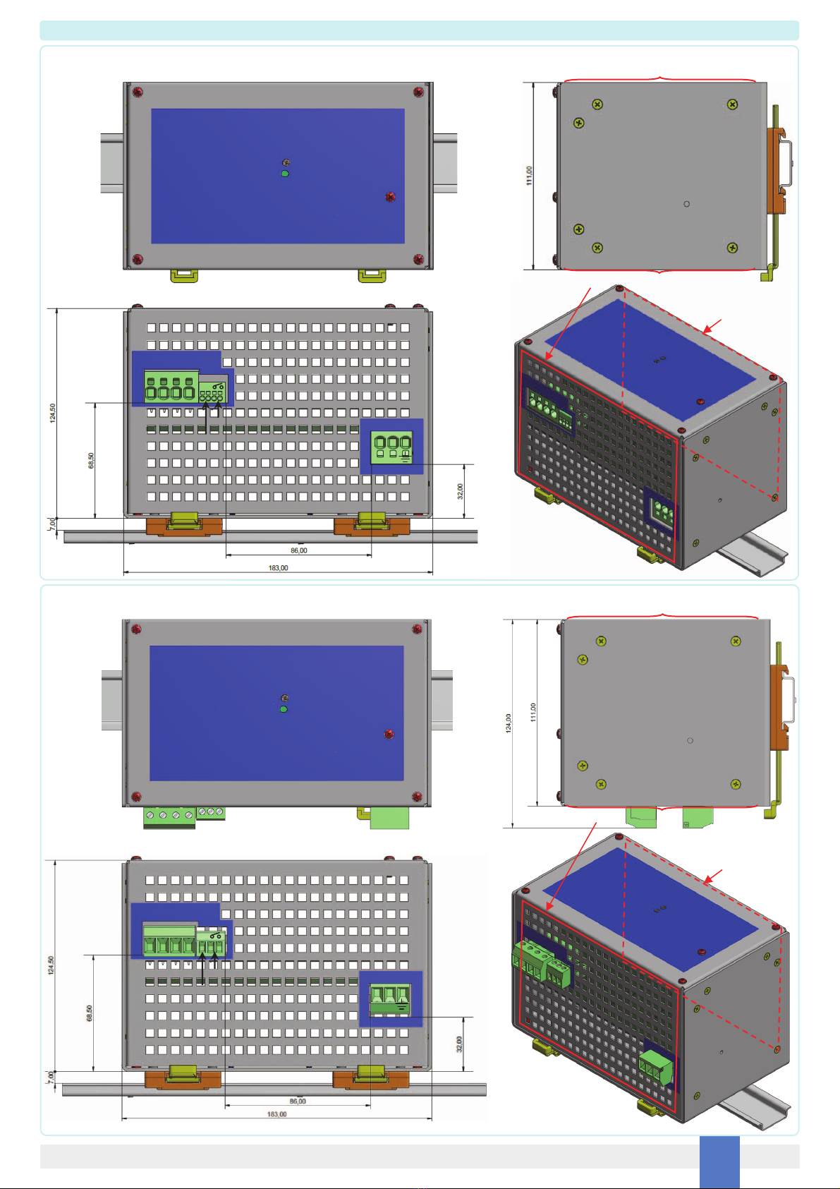
Output voltage setting - Fault indications
The output voltage can be set from 23.6 to 26.1 Vdc by a front panel trimmer.
Under voltage threshold is set to 22 V, while Over voltage threshold is set to 28 V.
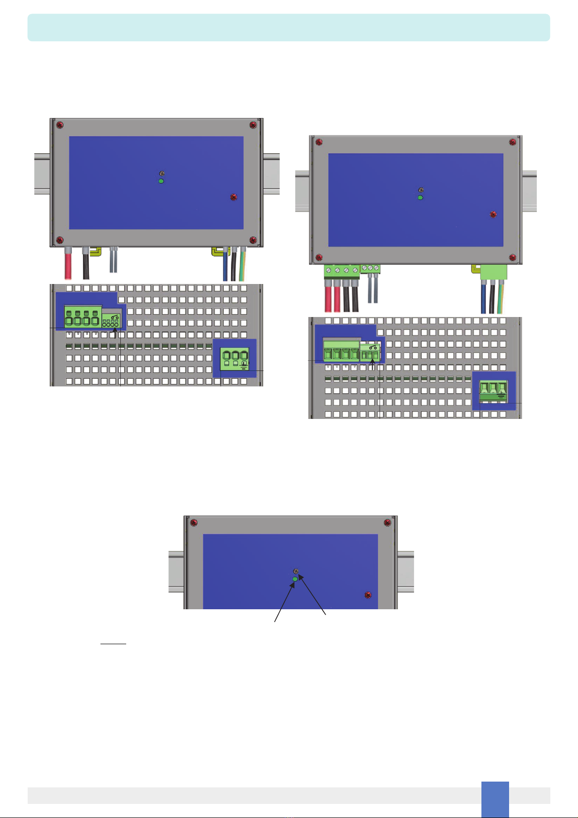
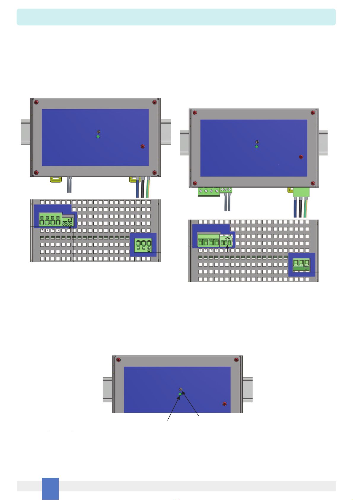
A front panel power ON green LED signals that mains voltage is applied to the power module and normal DC output voltage is present on DC output terminal block.
Power module Fault conditions are signaled by opening contact of NE relay (in normal condition contact is closed) on the “Fault” terminal block. Faults can be:
Under voltage Vout < 22 V.
Over voltage Vout > 28 V.
In absence of under / over voltage fault, the green Power ON LED is ON if output voltage is within 22 V - 28 V range
If output voltage goes below 22 V, the green Power ON LED blinks and remains steady for values lower than 22.5 V.
If output voltage goes over 28 V, the green Power ON LED is OFF and remains steady for values higher than 27.5 V.
After under / over voltage fault, coming back to normal condition, the green Power ON LED is ON if output voltage is within 22.5 V - 27.5 V range.
Warning
Storage
Disposal
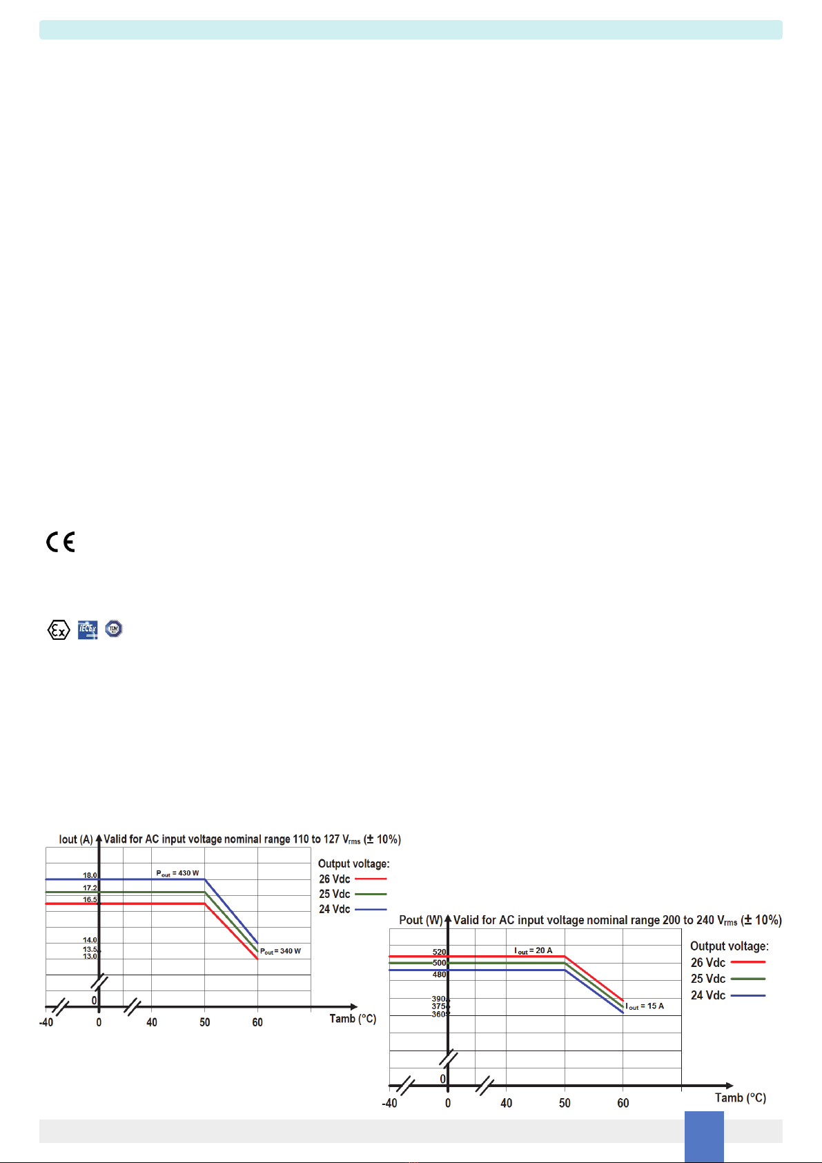
PSD1220 and PSD1220-098 are isolated Switching Power Supply units located in Safe Area or Zone 2, Gas Group IIC, Temperature T4 Hazardous Area within the specified
operating temperature limits -40°C ≤Tamb ≤+60°C and mounting conditions.
Read installation manual before operating the unit. Failure of proper installation or use of the equipment may damage the unit or cause severe personal injury.
PSD1220 and PSD1220-098 must be installed, wired, operated and maintained only by qualified personnel, in accordance to the relevant national/international installation
standards (e.g. IEC/EN60079-14 Explosive atmospheres - Part 14: Electrical installations design, selection and erection), following established installation guide lines.
PSD1220 and PSD1220-098 must be placed in an enclosure with IP4X protection degree when used in locations providing adequate protection against the entry of solid foreign
objects or water, capable of impairing safety, or be placed in an enclosure with IP54 protection degree for other locations. Substitution of components may impair suitability for
Zone 2.
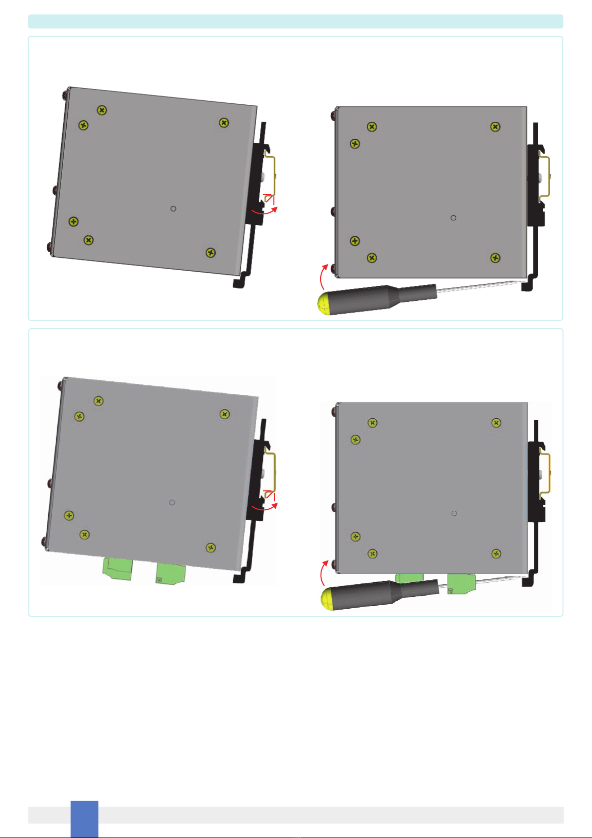
Explosion Hazard: to prevent ignition of flammable or combustible atmospheres, disconnect power and wait that green power-on LED is OFF before servicing or unless area is
known to be nonhazardous. Remove power before opening the case.
Clean only with dry cloth.
Green Power ON LED of power supply unit: check that green LED is OFF before disconnecting power supply.
Failure to properly installation or use of the equipment may risk to damage the unit or severe personal injury. The unit cannot be repaired by the end user and must be returned
to the manufacturer or his authorized representative. Any unauthorized modification must be avoided.
If after an incoming inspection the unit is not installed directly on a system (parts for spare or expansion with long storage periods) it must be conveniently stocked.
Stocking area characteristics must comply with the following parameters:
Temperature -40 to +70 °C, the -45 to +80 °C is meant for limited periods, -10 to +30 °C is preferred.
Humidity 0 to 95 %, 0 to 60 % humidity is preferred.
Vibration: no prolonged vibration should be perceivable in the stocking area to avoid loosening of parts or fatigue ruptures of components terminals.
Pollution: presence of pollutant or corrosive gases or vapors must be avoided to prevent corrosion of conductors and degradation of insulating surfaces.
The product should not be disposed with other wastes at the end of its working life. It may content hazardous substances for the health and the environment, to prevent possible harm
from uncontrolled waste disposal, please separate this equipment from other types of wastes and recycle it responsibly to promote the sustainable reuse of material resources.
This product should not be mixed with other commercial wastes for disposal.

PSD1220 & PSD1220-098 -SIL 3 Power Supply, 24Vdc, 20 A, Zone 2, DIN Rail MountingG.M. International ISM0370-3 5
Function Diagram for PSD1220
SAFE AREA or ZONE 2 GROUP IIC T4
PSD1220, dual AC supply, 1 redundant 20 A Output.
two modules connected in parallel to provide full redundancy on AC lines (AC1 and AC2) and one 20 A redundant output.
+
-
PSD1220, single AC supply, 1 redundant 20 A Output.
two modules connected in parallel to provide one 20 A redundant output.
+
-

PSD1220 & PSD1220-098 -SIL 3 Power Supply, 24Vdc, 20 A, Zone 2, DIN Rail Mounting G.M. International ISM0370-3
6
Function Diagram for PSD1220-098
SAFE AREA or ZONE 2 GROUP IIC T4
PSD1220-098, dual AC supply, 1 redundant 20 A Output.
two modules connected in parallel to provide full redundancy on AC lines (AC1 and AC2) and one 20 A redundant output.
+
-
PSD1220-098 PSD1220-098
PSD1220-098, single AC supply, 1 redundant 20 A Output.
two modules connected in parallel to provide one 20 A redundant output.
+
-
PSD1220-098 PSD1220-098
In this application, for each PSD1220-098, double wiring (on positive and negative output poles) is suggested between DC output connector and DC bus.

PSD1220 & PSD1220-098 -SIL 3 Power Supply, 24Vdc, 20 A, Zone 2, DIN Rail MountingG.M. International ISM0370-3 7
Installation Procedure - 1st step: Installation on DIN-Rail into a cabinet of PSD1220 and PSD1220-098
The PSD1220 must only be installed on a DIN-Rail as oriented in the following drawing. All dimensions are in millimeters (mm).
Right side view
The PSD1220-098 must only be installed on a DIN-Rail as oriented in the following drawing. All dimensions are in millimeters (mm).
Right side view
Bottom side view
AC Input
DC Output
Fault contact
Current Sharing Bus
+ + – – CSB
N L
Bottom side view
AC Input
DC Output
Fault contact
Current Sharing Bus
+ + – –
CSB
N L
RIGHT
LEFT
Front view UP
BOTTOM
PSD1220
Vout adjust trimmer
PWR On LED
RIGHT
LEFT
Front view UP
BOTTOM
PSD1220-098
Vout adjust trimmer
PWR On LED
Not cover up-side output flows of air grid
Not cover down-side input flows of air grid
Not cover up-side
output flows of air grid
Not cover up-side output flows of air grid
Not cover down-side input flows of air grid
Not cover up-side
output flows of air grid

PSD1220 & PSD1220-098 -SIL 3 Power Supply, 24Vdc, 20 A, Zone 2, DIN Rail Mounting G.M. International ISM0370-3
8
Installation Procedure - 1st step: PSD1220 and PSD1220-098 mounting on or removing from DIN-Rail
PSD1220
Mounting:
To mount the power supply module on 35 mm DIN-Rail, hook one side of the mounting
feet over the rail’s lip and press the module down firmly until fixed (see Fig.1).
Removing:
To remove a power supply module from the mounting rail, insert a blade screwdriver in
both mounting feet and lever (see Fig. 2).
Fig. 1
Push to
engage
Right side view Right side view
Pull the power supply module upwards
and remove from DIN-Rail
Fig. 2
PSD1220-098
Mounting:
To mount the power supply module on 35 mm DIN-Rail, hook one side of the mounting
feet over the rail’s lip and press the module down firmly until fixed (see Fig.3).
Removing:
To remove a power supply module from the mounting rail, insert a blade screwdriver in
both mounting feet and lever (see Fig. 4).
Fig. 3
Push to
engage
Right side view Right side view
Pull the power supply module upwards
and remove from DIN-Rail
Fig. 4

PSD1220 & PSD1220-098 -SIL 3 Power Supply, 24Vdc, 20 A, Zone 2, DIN Rail MountingG.M. International ISM0370-3 9
Installation Procedure - 2nd step (only for single PSD1220 or PSD1220-098 unit): Wiring of AC input, DC output, Fault contact output and
start up of power supply unit
RIGHT
LEFT
UP
BOTTOM
PSD1220
Vout adjust trimmer
PWR On LED
RIGHT
LEFT
UP
BOTTOM
PSD1220-098
Vout adjust trimmer
PWR On LED
Front view
AC Input
DC Output
Fault contact
+ + – –
N L
Bottom side view
Bottom side view
AC Input
DC Output
Fault contact
+ + – –
N L
The following images shows the wiring of AC input, DC output, Fault contact output terminal blocks for a single PSD1220 or PSD1220-098, not used in parallel/redundant configuration.
The unit must receive AC mains by means of a magnetic circuit breaker or switch with the following features:
B or C characteristic 8÷10 Amps when nominal low input voltage 110÷120 Vac ±10% is used;
B or C characteristic 4÷6 Amps when nominal high input voltage 220÷240 Vac ±10% is used.
AC line internal fuses are not user replaceable. The unit cannot be repaired by the end user and must be returned to the manufacturer or his authorized representative.
PSD1220-098 has got plug-in screw connection terminal blocks (which are extractable):
- for AC input terminal block, cable stripping length is 7 mm and
use a typical cable section of AWG15 (maximum AWG11 or 4 mm2);
- for DC output terminal block, cable stripping length is 7 mm and
use a typical cable section of AWG12 (maximum AWG11 or 4 mm2);
- for Fault contact output terminal block, cable stripping length is 7 mm and
use a typical cable section of AWG18 (maximum AWG14 or 2.5 mm2).
For each terminal block, tighten its screws with maximum 0.6 Nm torque.
PSD1220 has got plug-in spring connection terminal blocks (which are not extractable):
- for AC input terminal block, cable stripping length is 15 mm and
use a typical cable section of AWG15 (maximum AWG10 or 6 mm2);
- for DC output terminal block, cable stripping length is 15 mm and
use a typical cable section of AWG11 (maximum AWG10 or 6 mm2);
- for Fault contact output terminal block, cable stripping length is 10 mm and
use a typical cable section of AWG18 (maximum AWG16 or 1.5 mm2).
In addition, could be useful the following tools to press spring during cable connection:
- for AC input and DC output terminal blocks, use 3.5 x 0.6 mm flat-blade screwdriver;
- for Fault contact output terminal block, use 2.5 x 0.4 mm flat-blade screwdriver.
RIGHT
LEFT
UP
PSD1220 or PSD1220-098
Vout adjust trimmer
PWR On LED
Front view
Trimmer for output voltage adjusting
(use a little cross head isolated screwdriver)
Power ON
green LED
Start up:power the AC line to turn on PSD1220 or PSD1220-098 unit: Power ON green LED, on front panel, is ON and 24 Vdc (factory setting)
output voltage is present on DC output terminal block.
See page 4 for more information about Power ON green LED signalling.
The output voltage can be measured on DC output terminal block by means of a voltmeter, positioning its leads with touch prods on
terminal block screws (for PSD1220-098) or on terminal block springs (for PSD1220).
If it is required to set an output voltage value different from factory setting (24 Vdc), use the trimmer for output voltage adjusting.
Turn the trimmer clockwise (to the right) to increase output voltage (max. 26.1 Vdc) or turn the trimmer counterclockwise (to the left) to
decrease output voltage (min. 23.6 Vdc).

PSD1220 & PSD1220-098 -SIL 3 Power Supply, 24Vdc, 20 A, Zone 2, DIN Rail Mounting G.M. International ISM0370-3
10
Installation Procedure - 2nd step (only for PSD1220 or PSD1220-098 units in parallel/redundant configuration) - Section A:
Wiring of AC input, Fault contact output and pre-start up of power supply unit
RIGHT
LEFT
UP
BOTTOM
PSD1220
Vout adjust trimmer
PWR On LED
RIGHT
LEFT
UP
BOTTOM
PSD1220-098
Vout adjust trimmer
PWR On LED
Front view
AC Input
DC Output
Fault contact
+ + – –
N L
Bottom side view
Bottom side view
AC Input
DC Output
Fault contact
+ + – –
N L
The following images shows the wiring of AC input and Fault contact output terminal blocks for each PSD1220 or PSD1220-098 unit, used in parallel/redundant configuration with other
units (maximum 10 pieces).
Each unit must receive AC mains by means of a magnetic circuit breaker or switch with the following features:
B or C characteristic 8÷10 Amps when nominal low input voltage 110÷120 Vac ±10% is used;
B or C characteristic 4÷6 Amps when nominal high input voltage 220÷240 Vac ±10% is used.
The AC circuit breaker or switch separates each unit from other ones when they are connected to the same AC mains.
AC line internal fuses are not user replaceable. The unit cannot be repaired by the end user and must be returned to the manufacturer or his authorized representative.
To guarantee full redundance configuration from the input to the output of the whole power system (composed by two or multiple of two units, with a maximum of 10 units), it’s necessary
to use two AC mains (AC1 and AC2) with different Lines and Neutrals but the same Earth Ground connection. Half units of whole power system are connected to AC1 mains while the
other ones are connected to AC2 mains. However, each unit must receive AC1 or AC2 mains by means of a magnetic circuit breaker, which separates each unit from other ones.
At page 5 (for PSD1220) or 6 (for PSD1220-098), it’s shown a functional diagram of two units, used in parallel/redundant configuration with single or double AC mains.
PSD1220-098 has got plug-in screw connection terminal blocks (which are extractable):
- for AC input terminal block, cable stripping length is 7 mm and
use a typical cable section of AWG15 (maximum AWG11 or 4 mm2);
- for Fault contact output terminal block, cable stripping length is 7 mm and
use a typical cable section of AWG18 (maximum AWG14 or 2.5 mm2).
For each terminal block, tighten its screws with maximum 0.6 Nm torque.
PSD1220 has got plug-in spring connection terminal blocks (which are not extractable):
- for AC input terminal block, cable stripping length is 15 mm and
use a typical cable section of AWG15 (maximum AWG10 or 6 mm2);
- for Fault contact output terminal block, cable stripping length is 10 mm and
use a typical cable section of AWG18 (maximum AWG16 or 1.5 mm2).
In addition, could be useful the following tools to press spring during cable connection:
- for AC input terminal blocks, use 3.5 x 0.6 mm flat-blade screwdriver;
- for Fault contact output terminal block, use 2.5 x 0.4 mm flat-blade screwdriver.
RIGHT
LEFT
UP
PSD1220 or PSD1220-098
Vout adjust trimmer
PWR On LED
Front view
Trimmer for output voltage adjusting
(use a little cross head isolated screwdriver)
Power ON
green LED
Pre-Start up:power the AC mains to turn on PSD1220 or PSD1220-098 unit: Power ON green LED, on front panel, is ON and 24 Vdc (factory setting)
output voltage is present on DC output terminal block.
See page 4 for more information about Power ON green LED signalling.
The output voltage can be measured on DC output terminal block by means of a voltmeter, positioning its leads with touch prods on terminal
block screws (for PSD1220-098) or on terminal block springs (for PSD1220).
Use the front panel trimmer for output voltage adjusting. Turn the trimmer clockwise (to the right) to increase output voltage (max. 26.1 Vdc)
or turn the trimmer counterclockwise (to the left) to decrease output voltage (min. 23.6 Vdc).
Warning: for correct current sharing operation between units, the power supply modules must have output voltages calibrated within ± 0.3 V.
Finally, unpower AC mains, turning off PSD1220 or PSD1220-098 unit.
The following sub-step (pre-start up) must not be executed if each PSD1220 or PSD1220-098 output voltage factory setting to 24 Vdc is corrected for your applications.
Instead, execute this sub-step (pre-start up) if it’s necessary to set up a different value for each PSD1220 or PSD1220-098 output voltage in the range 23.6 to 26.1 Vdc.
For each PSD1220 or PSD1220-098 used in parallel/redundant configuration, execute the following sub-step, where only one unit at time is powered by AC mains, while other units are
in shutdown state by opening their AC input circuit breakers.

PSD1220 & PSD1220-098 -SIL 3 Power Supply, 24Vdc, 20 A, Zone 2, DIN Rail MountingG.M. International ISM0370-3 11
Start up of whole power system:after wiring of the DC output lines and Current Sharing bus for each unit, power AC mains.
Therefore, each PSD1220 or PSD1220-098 unit turns on and the whole power system can drive the loads connected to the DC output lines.
Installation Procedure - 2nd step (only for PSD1220 or PSD1220-098 units in parallel/redundant configuration) - Section B:
Wiring of DC output, Current Sharing bus and start up of whole power system
At this step AC mains is unpowered.
The following images shows the wiring of DC output and Current Sharing bus terminal blocks for each PSD1220 or PSD1220-098 unit, used in parallel/redundant configuration with
other units.
For correct current sharing operation, all PSD1220 or PSD1220-098 units used in parallel/redundant configuration must have their current sharing bus terminal blocks connected
together by wiring.
At page 5 (for PSD1220) or 6 (for PSD1220-098), it’s shown a functional diagram of two units, used in parallel/redundant configuration, where DC output and Current Sharing bus
connections are shown.
PSD1220-098 has got plug-in screw connection terminal blocks (which are extractable):
- for DC output terminal block, cable stripping length is 7 mm and
use a typical cable section of AWG12 (maximum AWG11 or 4 mm2);
- for Current Sharing bus terminal block, cable stripping length is 7 mm and
use a typical cable section of AWG18 (maximum AWG14 or 2.5 mm2).
For each terminal block, tighten its screws with maximum 0.6 Nm torque.
PSD1220 has got plug-in spring connection terminal blocks (which are not extractable):
- for DC output terminal block, cable stripping length is 15 mm and
use a typical cable section of AWG11 (maximum AWG10 or 6 mm2);
- for Current Sharing bus terminal block, two equivalent poles are available for easy
daisy chain connection with other two units. Cable stripping length is 10 mm and
use a typical cable section of AWG18 (maximum AWG16 or 1.5 mm2).
In addition, could be useful the following tools to press spring during cable connection:
- for DC output terminal blocks, use 3.5 x 0.6 mm flat-blade screwdriver;
- for Current Sharing bus terminal block, use 2.5 x 0.4 mm flat-blade screwdriver.
RIGHT
LEFT
UP
BOTTOM
PSD1220
Vout adjust trimmer
PWR On LED
RIGHT
LEFT
UP
BOTTOM
PSD1220-098
Vout adjust trimmer
PWR On LED
Front view
AC Input
DC Output
Fault contact
+ + – –
N L
Bottom side view
Current Sharing Bus
CSB
Bottom side view
AC Input
DC Output
Fault contact
+ + – –
N L
Current Sharing Bus
CSB
This manual suits for next models
1
Table of contents
Other GMI Power Supply manuals