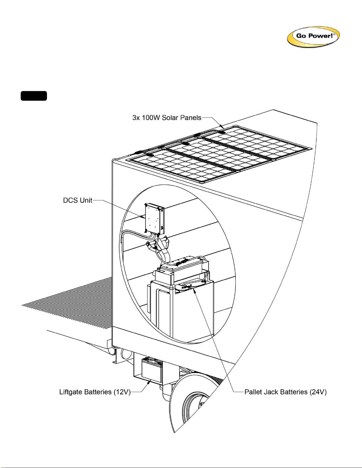
Go Power 300W User manual

Go Power! OEM Install Guide: 300W Dual Charging System
PROPRIETARY AND CONFIDENTIAL
© 2018 Valterra Products, LLC (Go Power!) 82675-E –INSTALL GUIDE, 300W DUAL CHARGING SYSTEM
Go Power!. 201 - 710 Redbrick Street, Victoria, BC Canada V8T 5J3 | Tel: +1.866.247.6527 | Fax: +1.866.607.6527 | Email: info@gpelectric.com
1 GENERAL
The Dual Charging System is designed to increase the life and performance of your liftgate and pallet jack batteries by providing a clean,
quiet and sustainable power source. The auto-switching functionality of the DCS unit allows for easy switching between charging the
liftgate and pallet jack.
This manual will aid in the process of installing the Go Power! Solar Kit. Please read and understand this manual before
installation. Review all figures included in this guide for the easiest and safest installation.
NOTE

Go Power! OEM Install Guide: 300W Dual Charging System
PROPRIETARY AND CONFIDENTIAL
© 2018 Valterra Products, LLC (Go Power!) 82675-E –INSTALL GUIDE, 300W DUAL CHARGING SYSTEM
Go Power!. 201 - 710 Redbrick Street, Victoria, BC Canada V8T 5J3 | Tel: +1.866.247.6527 | Fax: +1.866.607.6527 | Email: info@gpelectric.com
2 DISCLAIMERS
IMPORTANT: Please follow installation and wiring instructions exactly as outlined to ensure safety. We recommend installation by a
technician or professional electrician to ensure adherence to relevant electrical codes. We have made every reasonable effort to ensure
the accuracy of the instructions in this manual, but Go Power! does not guarantee that the information is error free, nor do we make any
other representation, warranty or guarantee that the information is accurate, correct, reliable or current. For additional information please
see www.gpelectric.com.
DISCLAIMER: This kit has been engineered for use in a mobile application. Any variance by the end-user is solely of their own discretion.
Valterra Power LLC (Go Power!) assumes no responsibility for improper installation in accordance with any laws and regulations
governing: cottage, residential or commercial applications. Go Power! disclaims liability for any direct, indirect or incidental damages
caused by, or in case of, installation not performed following the instructions and cautions in this manual. Go Power! will refuse requests
for exchanges or returns, resulting from the purchase and installation of items which do not comply with local codes. To avoid such
concerns Go Power! recommends installation by a professional electrician or technician. Examples that are shown within this manual are
for illustrative purposes only.
WARNING: The solar panels must be securely fastened only to a rigid surface on your truck/trailer roof. Failure to
do so could cause the panels to lift, flex and separate from the roof while in transit which could cause significant
damage, fire and/or injury.
3 CAUTIONS
Disconnect all power
sources before attempting
installation
Electricity can be very dangerous. Installation should be performed only by a licensed
electrician or qualified personnel.
Solar panel safety
Photovoltaic panels generate DC electricity when exposed to sunlight or other light
sources. Contact with the electrically active parts of the panel, such as terminals, can
result in burns, sparks and lethal shock whether the panel is connected or disconnected.
When panels are connected in series, voltages are additive. Consequently, a system
assembled from photovoltaic panels can produce high voltages, which constitute an
increased hazard. Do not touch terminals while panel is exposed to light. Cover the
panel face completely with opaque material to halt the production of electricity when
installing or working with panels or wiring.
Battery and wiring safety
Observe all safety precautions of the battery manufacturer when handling or working
around batteries. When charging, batteries produce hydrogen gas, which is highly
explosive. Work in a well-ventilated area and use caution when making or removing
electrical connections. Ensure wires are disconnected from their power sources when
wiring. Do not expose battery to open flame, cigarettes or sparks. Shield skin and eyes
from battery acid.
Ensure all connections are tight and secure. Loose connections may generate sparks
and heat. Be sure to check connections one week after installation to ensure they are
still tight.
Work safely
Wear protective eyewear and appropriate clothing during installation. Use extreme
caution when working with electricity and when handling and working around batteries.
Use properly insulated tools only.
Observe correct polarity at
all times
Reverse polarity of the battery terminals or solar terminals may damage the controller.
Do not exceed the voltage
and current ratings of the
Solar Controller
The total voltage of the solar system is the sum of the open circuit current of the solar
panels in series. The voltage of the array is the rated open circuit voltage of the solar
panels and is not to exceed 85V.
The system current (Imp) is not to exceed 20A.

Go Power! OEM Install Guide: 300W Dual Charging System
PROPRIETARY AND CONFIDENTIAL
© 2018 Valterra Products, LLC (Go Power!) 82675-E –INSTALL GUIDE, 300W DUAL CHARGING SYSTEM
Go Power!. 201 - 710 Redbrick Street, Victoria, BC Canada V8T 5J3 | Tel: +1.866.247.6527 | Fax: +1.866.607.6527 | Email: info@gpelectric.com
FIGURE 1
FIGURE 2
FIGURE 3
FIGURE 5
FIGURE 4
4 PLANNING
1. Move the pallet jack inside the truck/trailer to a suitable location
for charging, remove the cover for the pallet jack batteries and
disconnect the negative connection.
2. Turn off any accessories or equipment, including connection(s) to
the truck/tractor and disconnect all negative battery connections
from the liftgate batteries.
3. Determine the location for solar panel installation. Usually the
panels are mounted on the roof above the dual charging system
(DCS) unit to keep the wire run as short as possible.
4. Plan out wire routing before permanently mounting the solar
panel, DCS unit or any wiring. In many installations it is better to
mock up the whole installation before adhering the panels.
•Leave a gap of 1”between panels to allow for expansion
and contraction and to ensure solar cells are not covered
by 4Evaseal Tape.
•Ensure that all wiring is protected from rough or sharp
edges.
•Must use isopropyl alcohol or any other de-greaser. Must
ensure the solar panel location is completely clean. This
surface must be dry and above 45⁰F/8⁰C before adhering
the panel to the trailer roof.
•The location for DCS unit should be inside the
truck/trailer.
5 SOLAR PANELS
1. Remove the thin protective layer from the top surface of the panel.
2. Peel back a small portion (~5”) of the nonstick layer of the
adhesive backing tape (Figure 1) on the top or bottom of the solar
module. Place the side of the panel with the exposed adhesive in
the desired panel location.
3. Now that your panel is in position, remove the remainder of the
nonstick layer. Press down on the panel. Apply even pressure to
the entire panel to ensure it is properly adhered to the trailer roof.
4. Apply 4Evaseal Tape over the perimeter of the panel. Ensure
solar cells are not covered. If using tape, ensure good adhesion
around entire perimeter of solar panel. (Figure 2)
5. Repeat steps 1–4 for each panel. Locate panels adjacent to each
other.
6. Use the MC4 cables that are connected to the solar panel junction
box. Connect the positive MC4 connector to the negative
connector of the adjacent panel. This will connect the panels in
series and compound the output voltage of the panel. Connect
the 3ft. MC4 extension harness to the free connector of the
furthest panel from where the solar extension will be routed from.
(Figure 3)
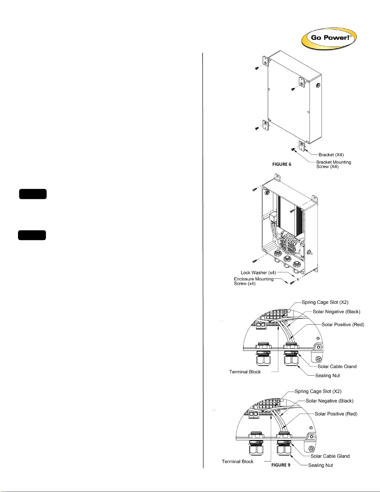
7. Connect the solar extension harness to the unused positive and
negative connectors on the panel and 3ft. MC4 extension
harness. Secure all harnessing to roof using 4Evaseal Tape, high-
bond adhesive, for example Sikaflex 221, or fasteners. (Figure 4)
8. Route the harness down the trailer to the DCS unit. If available,
use an existing conduit or channel. (Figure 5)
9. Cover solar panels with opaque material or the boxes they came
in to halt the production of electricity while installing solar wiring
to the DCS unit in Part 3.
NOTE

Go Power! OEM Install Guide: 300W Dual Charging System
PROPRIETARY AND CONFIDENTIAL
© 2018 Valterra Products, LLC (Go Power!) 82675-E –INSTALL GUIDE, 300W DUAL CHARGING SYSTEM
Go Power!. 201 - 710 Redbrick Street, Victoria, BC Canada V8T 5J3 | Tel: +1.866.247.6527 | Fax: +1.866.607.6527 | Email: info@gpelectric.com
FIGURE 8
FIGURE 9
FIGURE 6
FIGURE 7
6 DUAL CHARGING SYSTEM UNIT
1. Route the liftgate battery harness from the liftgate batteries to the
desired location of the DCS unit. Ensure the ring terminals can
reach the battery terminals, but do not attach at this time.
2. Find a location within the truck/trailer where the unit can be
mounted. Ensure this location meets the following criteria:
a. Close enough to where the pallet jack can be stored for
charging when not in use (within reach of pallet jack battery
harnesses).
b. High enough on the wall to avoid impact damage from pallet
jack operations.
c. Within reach of solar and liftgate battery harnesses.
d. Solar disconnect easily accessible.
3. Loosen the 4 screws for the cover of the unit and remove the
hardware bag.
4. Install the 4 brackets to the back surface of the unit using the 4
thread-locking machine screws (blunt end). (Figure 6)
•Ensure the screws are installed through the slotted
feature with the bracket lip held firmly against the unit
housing for proper support.
5. Mount the unit to the wall vertically using 4 of the self-tapping
screws (pointed end) and lock washers. (Figure 7)
•The self-tapping screws are designed for use with sheet
metal. Alternate fasteners may be used for increased
mounting strength or for other wall compositions.
6. Ensure the solar disconnect switch on the right side of the unit is
in the off position.
7. Route the solar extension harness to unit. Cut the harness so it
can easily reach, with at least 1ft of excess length.
8. Cut back the split tube from the harness so the solar wires can be
inserted through the solar cable gland (right) and the split tube is
as close to the gland as possible. (Figure 8)
9. Cut the solar wires so they can be installed into the closest vacant
terminal blocks. Ensure the wires will not interfere when installing
the unit cover back on.
10. Strip back the solar wire insulations 3/8” (10mm). Use a small flat
screwdriver, inserted into the spring cage slot, as a lever to
disengage/engage the wire clamping mechanism and insert the
bare wire into the terminal block. Ensure the solar positive wire
(red) is inserted into the red terminal block and the negative wire
(black) is inserted into black terminal block. (Figure 8)
11. Restrain the solar cable gland using a thin 1” wrench (crowsfoot
or open end) and tighten the sealing nut to 70 in. lbs. (max) using
a second 1” wrench.
12. Install a tie wrap around the cut end of the solar harness split tube
near the cable gland and securely tighten.
13. Repeat steps 7-12 for the liftgate battery harness, but with wires
inserted through middle cable gland, positive wire (red) inserted
into right terminal block and negative wire (black) inserted into left
terminal block (Figure 9), and cable gland and sealing nut
restrained and tightened with 1-1/16” wrenches.
NOTE
NOTE

Go Power! OEM Install Guide: 300W Dual Charging System
PROPRIETARY AND CONFIDENTIAL
© 2018 Valterra Products, LLC (Go Power!) 82675-E –INSTALL GUIDE, 300W DUAL CHARGING SYSTEM
Go Power!. 201 - 710 Redbrick Street, Victoria, BC Canada V8T 5J3 | Tel: +1.866.247.6527 | Fax: +1.866.607.6527 | Email: info@gpelectric.com
FIGURE 11
FIGURE 10
FIGURE 12
14. Mount the pallet jack battery extension harness from the unit to
the wall using the loop clamps and remaining lock washers and
self-drilling screws to ensure any harness strain is relieved by the
loop clamps and not the unit. (Figure 10)
15. Connect the pallet jack batteryharness to the pallet jack batteries.
Attach the red wire to the positive terminal on one side of the
battery bank and the black wire to the negative terminal on the
opposite side of the battery bank to ensure even charging. (Figure
11)
16. Route the pallet jack battery harness from the battery bank to a
location where the connector is accessible for frequent connecting
and disconnecting. (Figure 11)
17. Ensure the pallet jack disconnect switch (24V) on the left side of
the unit is in the off position.
18. Connect the pallet jack battery harness to the pallet jack battery
extension harness from the unit. (Figure 12)
19. Complete the connection from the unit to the liftgate batteries by
attaching the red wire to the positive terminal and the black wire
to the negative terminal. Note, if installing to multiple liftgate
batteries, connect as shown on pallet jack to ensure even
charging. (Figure 13)
20. Install any cable mounts, tie wraps or other wire management
parts (not included) to ensure the solar and battery harnesses are
properly strain relieved and clear from sharp edges and potential
damage from pallet jack operations.
21. Complete the connection from the unit to the solar panels by
turning on the solar disconnect switch. To ensure the solar panels
are charging the batteries, a clamp-on ammeter is required.
Ensure the solar panels are in the sunlight (opaque material
removed). Clip the ammeter around the positive wire of the liftgate
battery harness between the unit and the liftgate batteries.
Activate the liftgate for one cycle. Note, the solar charge controller
in the unit can take up to one minute to start charging, so there
may be a delay before current flow is registered on the ammeter.
22. To activate the second charging function, complete the
connection from the unit to the pallet jack batteries by turning on
the pallet jack disconnect switch (24V). Clip the ammeter around
the positive wire of the pallet jack battery harness between the
unit and the pallet jack batteries.
23. To reactivate the liftgate charging function, disconnect the pallet
jack battery harnesses by unmating the connectors.
24. Reinstall the covers of the unit and batteries after testing of both
charging functions is complete
LED Indications & Warning Functions
Table of contents
Other Go Power Batteries Charger manuals