Thank you for purchasing this product.
This TT685F camera flash applies to Fuji series cameras and is
compatible with TTL autoflash. With this TTL compatible flash, your
shooting will become simpler. You can easily achieve a correct flash
exposure even in complex light-changing environments. This
camera flash features:
● GN60 (m ISO 100, @200mm). 22 steps from 1/1 to 1/128.
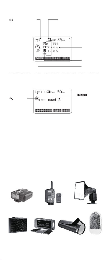
● Fully support Fuji series TTL camera flash. Workable as Master or
Slave unit in a wireless flash group.
● Use dot-matrix LCD panel to make clear and convenient
operations.
● With built-in 2.4GHz wireless remote system to support
transmitting and receiving.
● Provided multiple functions, include HSS (up to 1/8000s), second-
curtain sync, FEC, etc.
● Use optional FT-16S to adjust flash parameters & trigger the flash.
● Stable consistency and color temperature with good even lighting.
● Support with firmware upgrade.
Foreword
Compatible Camera Models
• This table only lists the tested camera models, not all Fuji cameras. For the
compatibility of other camera models, a self-test is recommended.
• Rights to modify this table are retained.
A
B
C
X-Pro2, X-T20 , X-T2 , X-T1
X-Pro1 , X-T10 , X-E1 , X-A3
X100F, X100T
Fuji cameras are divided into three kinds according to their
different controlling ways to camera flash:
Compatible camera models & functions support
A
B
C
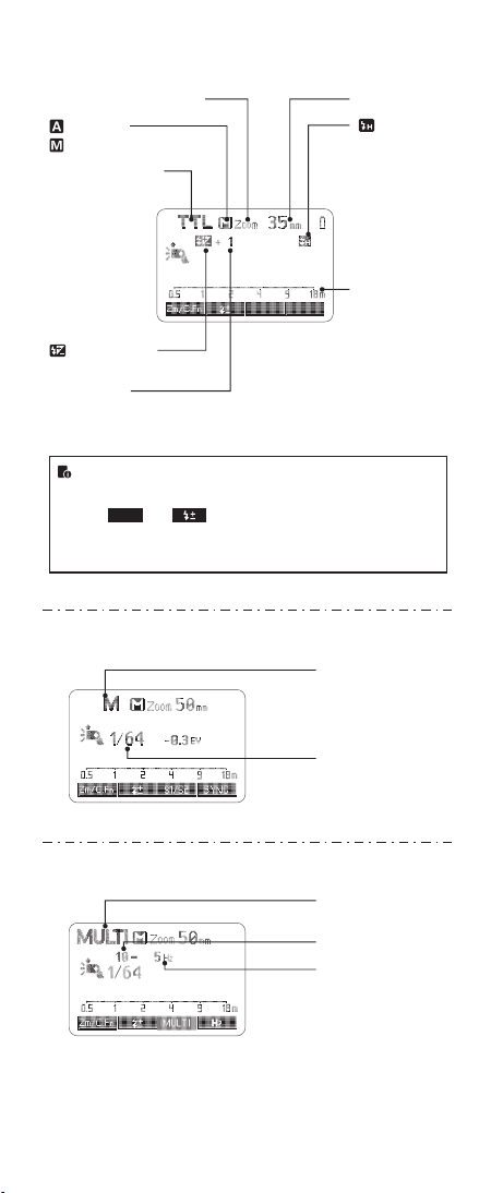
Camera Flash
TTL Flash M Manual Flash Multi
Strobo
-scopic
Flash
Stan-
dard REAR HSS(FP)REAR HSS(FP)
√ √ √ √ √ √ √
2.4G Wireless Control
√ √ √
√ √ √ √ √ √ √
√ √ √ √ √ √ √
√ √ √
√ √ -- √ √ -- √
-- -- -- -- -- -- -- --
A
B
C
AF-assist Beam
√
--
--
camera
Stan-
dard
TTL Flash M Manual Flash Multi
Strobo
-scopic
Flash
Stan-
dard REAR HSS(FP)REAR HSS(FP)
Stan-
dard
1. X 100T do not have second curtain sync (REAR) function.
2. The AF assist beam will light up when the shutter is at low speed (<200).
- 25 - - 26 -
Always keep this product dry. Do not use in rain or in damp
conditions.
Do not disassemble. Should repairs become necessary, this
product must be sent to an authorized maintenance center.
Keep out of reach of children.
Stop using this product if it breaks open due to extrusion, falling
or strong hit. Otherwise, electric shock may occur if you touch
the electronic parts inside it.
Do not fire the flash directly into the eyes (especially those of
babies) within short distances. Otherwise visual impairment
may occur.
Do not use the flash unit in the presence of flammable gases,
chemicals and other similar materials. In certain circumstance,
these materials may be sensitive to the strong light emitting
from this flash unit and fire or electromagnetic interference may
result.
Do not leave or store the flash unit if the ambient temperature
reads over 50℃. Otherwise the electronic parts may be
damaged.
Turn off the flash unit immediately in the event of malfunction.
Warning