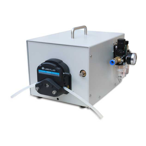
Golander pump CT3000F User manual

CT3000F Intelligent Dispensing Gear Pump
Operating Manual

Contents
Safety Precautions...............................................................................1
1 Introduction.......................................................................................2
2 Functions and Features.....................................................................2
3 Specifications....................................................................................3
4 Components and Connectors............................................................4
5 Display Panel and Operating Keypads...............................................5
5.1 Keypad ...................................................................................5
5.2 LCD Touch Screen Display......................................................6
5.3 System Settings....................................................................11
6 External Control Interface................................................................17
7 Operation Instructions.....................................................................18
7.1 Before Operation...................................................................18
7.2 Power Connection.................................................................18
7.3 Install pump head and tubing.................................................18
7.4 First Run Wizard ...................................................................20
7.5 Flow Rate Calibration ............................................................21
7.6 Working Mode.......................................................................25
7.7 External Control Mode...........................................................29
7.8 Communication Mode............................................................31
7.9 Footswitch.............................................................................32
8 Maintenance...................................................................................34
8.1 Warranty ...............................................................................34
8.2 Regular Maintenance ............................................................34
8.3 Malfunction Solutions ............................................................34
9 Dimensions.....................................................................................36
10 Naming Rule.................................................................................37
11 Suitable Pump Heads....................................................................37

Golander CT3000F Dispensing Gear Pump
1
Safety Precautions
Danger
•Please use the correct AC power voltage source shown on the
sticker attached tothe equipment to avoid any damage. Please do
not open the case. It may cause malfunction or electric shock. For
maintenance, please contact the manufacturer or distributor
directly.
•To install or remove the pump head, please first turn off the power
supply. Handle the flange of the pump head carefully and refrain
from using pliers to clamp it, as this may cause inner core
displacement or even permanent damage to the pump.
Warning
•Tubing breakage may result in fluid being spayed from the pump.
Take appropriate measures to protect the operator and
equipment.
•Always remove power from the pump before attempting any
maintenance or cleaning operation.
•Remove power from the pump before connecting or
disconnecting the external control device or communication
interface.
•The pump is equipped with a grounded plug, and it must remain
well–grounded at all times.
•This product is not designed for, nor intended for use in patient-
connected applications, including, but not limited to, medical and
dental use.
•Avoid any foreign bodies, including sealant or Teflon tape, from
entering the pump when sealing the tubing. Only remove the two
covers on the pump head when installing a connector or tubing,
•It is strongly recommended that when using the pump, especially
for the inlet, the tubing size should correspond to the pump's

Golander CT3000F Dispensing Gear Pump
2
capacity to avoid cavitation caused by inadequate fluid leading to
abnormal wear. Under no circumstances should the pressure
between the inlet and outlet exceed 20 bar / 290 psi.
•It is strongly recommended to add a filter to the pump's inlet to
filter out particles larger than 10 um to prevent abnormal wear and
tear of internal components. Ensure the filter surface area is large
enough to avoid pressure loss in the loop. Regularly check the
filter to ensure it functions effectively. If a vacuum gauge is
installed after the filter, and the vacuum increases by more than
0.1 bar, clean or replace the filter.
•The gear pump can only transfer liquid in one direction.
1Introduction
CT3000F is a high-performance, low-noise micro gear pump, providing a
speed range from 50 to 3000 rpm, with a 1 rpm resolution. Its brushless
servo motor and stainless-steel magnetic drive pump head enable the
continuous and smooth transfer of fluids. The color LCD touch screen
offers an intuitive and clear display, while the various working modes
make it suitable for a wide variety of uses. Equipped with a standard
MODBUS RS485 interface, the pump can be easily controlled by external
devices, such as computers, human-machine interfaces, or PLCs.
2Functions and Features
•Compatible with variable pump heads
•Suitable for high-viscous and high-pressure liquid transfer
•Minimal pulsation and low noise operation
•Magnetic coupling drive, easy maintenance
•Brushless servo drive, high efficiency, maintenance free
•Color LCD display, touch screen
•Displays and controls flow rate
•Multiple working modes
•Includes a flow calibration wizard for accuracy
•Intelligent temperature control

Golander CT3000F Dispensing Gear Pump
3
•External signal controls start/stop/dispensing; external analog
signal adjusts speed
•RS485 MODBUS communications interface
•Stainless steel case
3Specifications
Pump Head MS204, MS209, MS213
(PEEK gear material)
Communication
RS485, supports Modbus communication
protocol
Display
Color LCD display
Flow Range
15-2700 mL/min
Speed Range
50-3000 rpm/min
Speed Resolution
1rpm
Liquid Viscosity
≤200cSt
Particle Size
≤10um
Operation
Keypad and touchscreen
Control Mode
Flow Mode, Time Dispense, Volume
Dispense, Copy Dispense
Display Mode Color LCD
External Control
5V (12V/24V optional) to control Start/Stop
0-5V (0-10V,4-
20mA optional) to control
speed
Power Supply
AC 100-240V, 50Hz/60Hz
Consumption
<150W
Working Environment Temperature 0-40°C, humidity <80%
Dimensions (LxWxH) 320x150x237mm (12.6x5.9x9.3inch)
Drive Weight
5.5kg (12.1lbs)
P Standard
IP31

Golander CT3000F Dispensing Gear Pump
4
4Components and Connectors
Handle
Control Pane
Pump Head Holder
Magnetic Coupling Drive
Pump Head
Sticker
External Control Port
Power Switch
Power Plug
Cooling Fan
Figure 1. Components and Connectors

Golander CT3000F Dispensing Gear Pump
5
5Display Panel and Operating Keypads
Display key
Prime Key
LCD touch screen
Start/Stop
Working mode
Figure 2. Display Panel
5.1 Keypad
START/STOP Key. Press to start or stop the drive.
DISP
DISPLAY Key. Use to switch the display mode.
PRIME Key. Press to operate the pump at the maximum
allowable speed. Press again to return to the previous state.
MODE key. When the drive is not running, use this key to change
the working mode.
MODE

Golander CT3000F Dispensing Gear Pump
6
5.2 LCD Touch Screen Display
15.00mL/min
+ -
MS204 50 RPM
AB C D E
FG
H
I J K L M N
Flow 25ºC
Figure 3. Main Display Screen
5.2.1 A - Keypad Lock
Press the icon to lock/unlock the keypad. When the keyboard is
locked, a user cannot modify the control mode and system parameters.A
Password can be set to unlock the keypad, preventing accidental
changes to the system parameters.
Keypad locked
Keypad unlocked
Figure 4. Keypad Lock

Golander CT3000F Dispensing Gear Pump
7
5.2.2 B - Tone Button
Press the icon to turn on/off the key tone.
Tone on
Tone off
Figure 5. Key Tone
5.2.3 C - Control Mode
Press the icon to access the Control Mode window, where you can
choose from four available control modes as shown below:
Control Mode
Internal Ctrl
Current Ctrl
Foot Ctrl
Voltage Ctrl
Figure 6. Control Mode
•Internal Ctrl - Internal Control Mode. Operate the pump using the
keypad and touch screen.
•Foot Ctrl- Footswitch Control Mode. Footswitchcontrols start/stop,
while utilizing the keypad and touch screen for other operations.
•Current Ctrl- Current Control Mode. An external 4-20mA analog
current signal controls the rotating speed, and a logic level signal
controls start/stop. The keypad is disabled in this mode.
•Voltage Ctrl - Voltage Control Mode. An external 0-5V or 0-10V
analog voltage signal controls the rotating speed, and a logic

Golander CT3000F Dispensing Gear Pump
8
level signal controls start/stop. The keypad is disabled in this
mode.
Internal Control
Mode Footswitch
Control Mode Current Control
Mode Voltage Control
Mode
Figure 7. Control Mode Icon
5.2.4 D - Quick Settings
Press the icon to access the quick setting interface to reset the
accumulated liquid volume and the time. Under the fluid volume dispense
mode, time dispense mode and copy dispense mode, there are five
groups of preset data. Use the Prev key and Next key to select the
desired group. The settings displayed on the main screen will adjust
accordingly.
Quick Settings
Return
Cumulative Volume Clear
Cumulative Cycles Clear
Quick Settings
Return
Cumulative Volume Clear
Cumulative Cycles Clear
No.1: 5.000 mL 001.0s
6.000 mL/min 1 T
NextPrev
Flow Mode
Other Modes
Figure 8. Quick Settings
5.2.5 E - System Settings
Press this icon to access the System Settings menu and change the
parameters shown on the screen.

Golander CT3000F Dispensing Gear Pump
9
5.2.6 F - Flow Rate Setting
It displays the current flow rate setting. When the drive is not running,
press it to input the desired value in the pop-up window. Please pay
attention to the range of the value and flow rate unit.
1 -3
2
.
7
4
8
->
65
9
0
ESC
OK
0.9
Max:9.0ml/min Min:0.6ul/min
Figure 9. Flow Rate Setting
5.2.7 G - Flow Rate Unit
It shows the current flow rate unit, mL/min.
5.2.8 H - Fine Adjustment Button
When the drive is running, utilize the fine adjustment button to adjust the
flow rate in real time. Briefly press the button or button to
increase or decrease the flow rate. Hold down the buttons for rapid value
adjustment.
5.2.9 I - Communication State
It displays the current state of RS485 communication.
Communication
connected
Communication
disconnected
Figure 10. Communication State

Golander CT3000F Dispensing Gear Pump
10
5.2.10 J - Running state
It shows the current operational status. When the drive is not running, the
following icon will be displayed.
Figure 11. Drive Stopped
Upon initiation of the drive, the icon transforms into an animated
illustration as depicted below:
Figure 12. Running Animation
5.2.11 K - Pump Head Model
It shows the current configured pump head model. For instance, "MS204"
denotes the MS204 pump head.
5.2.12 L - Working Mode
It shows the current working mode, such as Flow Mode, Volume
Dispense Mode, Time Dispense Mode, or Copy Dispense Mode.
5.2.13 M - Speed or Cumulative Cycles
It shows the current speed or cumulative dispense cycles, switchable by
pressing the MODE key. In the event that the speed exceeds the
maximum allowable speed, it will display U_Overflow.Conversely, if the
speed falls below the minimum allowable speed, it will display
D_Overflow. The cumulative cycles can be reset within the Quick
Settings menu.
5.2.14 N - Internal Temperature or Cumulative Volume
It shows the internal temperature of the drive or cumulative volume that
the pump has delivered. The cumulative volume can be reset within the
Quick Settings menu.

Golander CT3000F Dispensing Gear Pump
11
5.3 System Settings
When the drive is not running, press the icon to access the System
Settings menu.
Figure 13. System Settings
5.3.1 Setup
Configure the general parameters as shown below.
General Settings
PumpHead
IrDA
Language
Remote
Com
Other
Return
Figure 14. General Settings
•PumpHead - Choose the model of the installed pump head.

Golander CT3000F Dispensing Gear Pump
12
Pump Head Setup
MS204
OK
MS204
MS209
MS213
Please choose pump head.
Figure 15. Pump Head Select
•Language - Choose the display language as English only.
•IrDA - Activate or deactivate the infrared control function.
IrDA Setup
Return
This function is to turn on/off
IrDA control.
Enable
Figure 16. IrDA Setup
•Remote
This setting enables the external control mode, which includes the
options of Logic Level control mode or Pulse control mode. When set
to Logic Level, the pump's state will change upon closure or opening
of an external switch. This mode is intended for use with a maintained
switch. When set to Pulse, the pump's state will change upon the
switch being closed and then opened again. This mode is designed
for use with a normally open momentary switch.

Golander CT3000F Dispensing Gear Pump
13
Remote Control
OK
Please choose remote control
by logic level or pulse input.
Pulse
Figure 17. Remote Control Mode
•Com
This setting pertains to RS485 MODBUS communication and includes
parameters such as baud rate, transmission mode, and pump
address. To modify the address, click on the address number
displayed on the screen, then input the desired value in the pop-up
window. Restart the pump to apply the modified settings..
Baud(bps):
Return
Mode:
4800
19200
9600
38400
Pump No. 1
Computer
PLC
Figure 18. Communication Settings
•Other
Set up the acceleration time of the drive to start from 0 to the
maximum speed.

Golander CT3000F Dispensing Gear Pump
14
Other Setup
Return
0 to max speed time 0.5 s
Figure 19. Anti-Drip Settings
5.3.2 Calibrate
Ensure accurate display of the current flow rate/volume by conducting the
Flow Rate Calibration.
Note: Calibration is necessary for precise flow rate display.
MS204 Calibration
Return
15.00 mL/min
96.01 mL
Next
Suggested testing vol>96.01mL
To reach 0.5% precision.
Figure 20. Flow Rate Calibration
5.3.3 Password
This function enables the setup of a password to secure the keypad and
prevent accidental parameter changes. The default password is empty.

Golander CT3000F Dispensing Gear Pump
15
Please enter a password
Set
1
Del Enter
8765432
9 F
EDCBA
0
Figure 21. Password
5.3.4 Info
This section provides comprehensive information about the pump.
Information
FlowCurve
SysInfo WorkInfo
Defaults
Return
Figure 22. Information
•Flowcurve - To show the flow curve of the pump head (not
currently applied).
•SysInfo - Provides details such as software version, memory size,
operating temperature, etc.

Golander CT3000F Dispensing Gear Pump
16
System Information
Return
Software : V1.0 2015-01
Hardware : 16M FLASH
Speed : 1RPM±0.5%
Temperation : 25ºF
Figure 23. System Information
•Defaults
This feature resets the pump to its factory settings. Restart the pump
to apply the new settings. Additionally, the system can be restored to
its factory settings by simultaneously pressing the
DISP
and
MODE
when powering on the pump, then releasing the keys after the beep.
Factory Reset
Return
Warning! The system will be
restored to factory default settings.
Reset
Figure 24. Factory Reset
•Workinfo
It shows essential information including the total power-on time,
running time, and power cycles.

Golander CT3000F Dispensing Gear Pump
17
Work Information
Return
Open time: 0 D 9 H 58 M
Run time: 0 D 1 H 25 M
SN:?D4MM6F=
OpenCounter: 00000153 T
Figure 25. Work Information
5.3.5 Return
To return to the main display screen.
6External Control Interface
1 2 3 4 5 6 7 8
910 11 12 13 14 15
DB15
Mark
Note
1
ADC_W
Positive of external analog input
2
B
Communication interface, B pole of RS485
3
A
Communication interface, A pole of RS485
4
VCC_W
External DC power input
5
DAC
Analog voltage signal output
6
7
8
COM
Ground of external power
9
AGND
Negative of analog signal input

Golander CT3000F Dispensing Gear Pump
18
10 +12V Positive of internal +12V power source
11
GND
Ground of Internal power source
12
13
RS_W
External start/stop signal input
14
15
RS
Start/stop signal output
7Operation Instructions
7.1 Before Operation
1) Please check the packing slip to verify that everything is intact and
undamaged in the package. If there are any issues, please reach out
to the manufacturer or distributor for assistance.
2) Carefully read through the provided instructions to familiarize
yourself with the setup and operation process.
3) Allow for at least 200 mm of space behind the pump during
operation to ensure proper ventilation.
7.2 Power Connection
Before connecting the power, ensure that the voltage requirements
specified on the pump's sticker are met. Follow these steps:
Connect the power cord to the rear power connector of the pump. Insert
the opposite end of the power cord into an appropriate electrical outlet.
Activate the power by using the switch located at the rear of the pump.
pump.
7.3 Install pump head and tubing
7.3.1 Install pump head
1) Place the pump head into the designated pump head holder,
ensuring that the entrance remains horizontal.
2) Align the pump head with the bracket's mounting holes. Secure
the pump head onto the bracket using the provided M3x8 mm
Table of contents
Other Golander pump Water Pump manuals

Golander pump
Golander pump WT300F User manual

Golander pump
Golander pump KZ25 User manual
Golander pump
Golander pump BT100S User manual

Golander pump
Golander pump WT600F-65 User manual

Golander pump
Golander pump BT103S User manual

Golander pump
Golander pump FG600S User manual
Golander pump
Golander pump DT15-14 User manual
Golander pump
Golander pump BT103S User manual

Golander pump
Golander pump BQ80S V2 User manual

Golander pump
Golander pump WG600S User manual