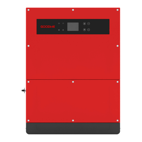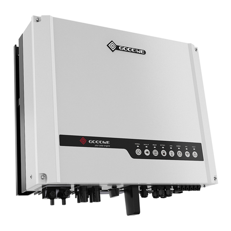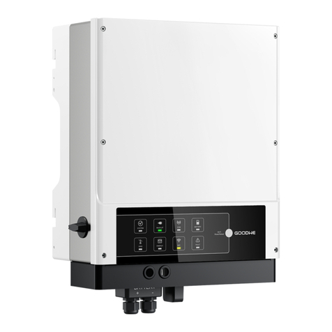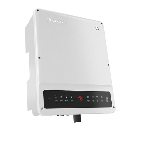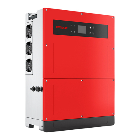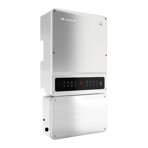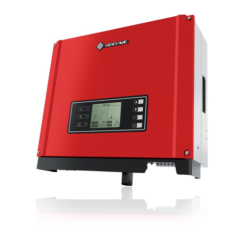
The DNS series inverter of Jiangsu GOODWE Power Supply Technology Co, Ltd. (hereinafter
referred to as GOODWE) strictly conforms to related safety rules in design and test. Safety regula-
tions relevant to the location shall be followed during installation, commissioning, operation and
maintenance. Improper operation pose a risk of electric shock or damage to equipment and
property. (DNS Dual-MPPT, Single-Phase)
• Installation and connection of inverters must be performed by qualified personnel, in compli-
ance with local electrical standards, regulations and the requirements of local power authorities
and/or companies.
• To avoid electric shock, DC input and AC output of the inverter must be disconnected for at least
5 minutes before performing any installation or maintenance.
• The temperature of some parts of the inverter may exceed 60℃ during operation. To avoid being
burnt, do not touch the inverter during operation. Let it cool before touching it.
• Keep children away from the inverter.
• Do not open the front cover of the inverter, except operating the wiring terminal (as instructed in
this manual). Touching or changing components without authorization may cause injury to
people, damage to inverters and annulment of the warranty.
• Static electricity may damage electronic components. Appropriate methods must be adopted to
prevent such damage to the inverter; otherwise the inverter may be damaged and the warranty
annulled.
• Ensure the output voltage of the proposed PV array is lower than the maximum rated inut voltage
of the inverter; otherwise the inverter may be damaged and the warranty annulled.
• When exposed to sunlight, the PV array generates dangerous high DC voltage. Please operate
according to our instructions, or it will result in danger to life.
• PV modules should have an IEC61730 class A rating.
• If the equipment is used in a way not specified by the manufacturer, the protection provided by
the equipment's design may be impaired.
• To completely isolate the equipment: switch off the DC switch, disconnect the DC terminal, and
disconnect the AC terminal or AC breaker.
• Insert or pull the AC and DC terminals when the inverter is powered on is prohibited.
• If there are more than 3 PV strings on input side, additional fuse installation will be suggested.
• An earthing photovoltaic system requires the connection of an Arc fault detector on DC side.
• The inverter can exclude the possibility of DC residual currents to 6mA in the system, where an
external RCD is required in addition to the build=in RCMU, type A RCD must be used to avoid
tripping.
• The PV- is not grounded as default configuration.
3 Product Introduction
3.1 Inverter Overview
To ensure IP65, inverters must be sealed well, please install the inverters within one day
after unpacking. Please seal all used terminals / holes, any unused terminals / holes are
not allowed to be kept open. Make sure that there is no risk of water or dust entering
terminals / holes.
GOODWE provides standard manufacture warranty to inverter products, which will be delivered
with the product. We also provide prepaid warranty extension solution to our customer. You can
find the details about the terms and solutions from official website: https://en.goodwe.com/war-
ranty.asp.
Item
1
2
3
4
5
6
7
8
9
10
11
Name
PV Input Terminal
DC Switch
Communication Module Port
Communication Cable Port
AC Output Terminal
LED
LCD
Button
Ground Terminal
Mouting Plate
Heat Sink
1 2 3 4 5 76 8 9 10 11
Description
For PV string connection
During normal operation, it can shut down the inverter after
it is disconnected from the grid by the AC breaker.
For 4G/LAN/GPRS communication; RS485 communication
For CT/DRED/RSD Communication
For AC cable connection
Display the state of the inverter
Operation data viewing and parameter configuration.
For configuration and viewing parameters.
Connect the invter to the ground and avoid electric hazard.
Hang the inverter on the wall.
For heat dissipation.
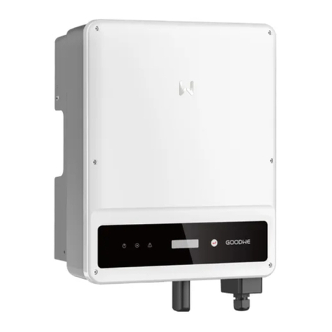
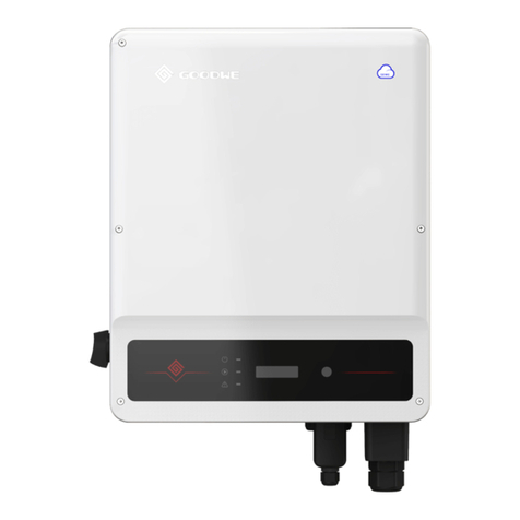
1. PV Input Terminal 2. DC Switch 3.
WiFi/4G/LAN/GPRS Communication
Module Port or RS485
Communication Cable Port
4.
DRED/CT/Remote Shut
down Communication
Cable Port
5. AC Output
Terminal 6. LED
7. LCD 8. Button 9. PE Terminal
10. Mounting Plate 11. Heat Sink
03 04
