OPERATION
1. Check reel for correct operation by slowly pulling out the hose. A “clicking” noise will be
heard every half revolution of the drum.
2. To latch the reel, pull out the hose and allow it to retract after hearing the first second or third
“ click”.
3. To unlatch, slowly pull out the hose until the “clicking” noise stops, then let the hose retract
until the hose stop rests against the hose guide.
Note: To avoid damage to the reel, always hold on to the hose while it is rewinding.
4. Periodically check the hose condition for wear or damage, and check the swivel fitting for
leakage. Replace any worn, damaged, or leaking parts.
Adjustment of Spring Tension
1. Pull out approximately 6ft or 2m of hose and allow the drum to latch.
2. Remove hose stopper from hose, and feed hose back through guide.
3. Wrap the pulled hose one time around the drum to increase tension or un-wrap hose one
time from drum to decrease tension.
4. Re-insert hose through guide, and install stopper onto hose end.
5. Unlatch the Drum and check tension. Pull hose from reel, and adjust stopper position if
necessary.
Replacement of Swivel Seal
1. Turn off and disconnect supply line from swivel inlet.
2. Remove swivel assembly from reel axle.
3. Remove clip from swivel, and take apart. Note: You may want to remove swivel from reel
hose end, but this is not necessary unless a new swivel is being installed.
4. Replace the seals and reassemble swivel.
5. Use Teflon type or thread sealant on swivel thread fitting, reconnect the swivel thread fitting
with axle.
6. Re-connect inlet supply line.
7. Run pressure test and check whether leak or not at each connection.
Replacement of Hose
1. Turn off supply to reel.
2. Pull out all the old hose and lock the reel in this position.
Cation: Make sure reel drum is securely locked and cannot rotate back.
3. Remove two hose clamps from hose.
4. Carefully disconnect hose from swivel joint on side of reel, or male fitting in axle center and
remove old hose.
5. Feed new hose through guide and opening in drum, and connect to swivel. Re-install two
hose clamps, on inside and outside of drum flange. Install stopper on other end of hose in
the same position as before.
6. Carefully release the drum latch, and slowly allow the hose to wind onto the reel.
Note: Final spring adjustment is accomplished by adding or removing wraps of hose around
the drum. (Details see spring tension adjustment).
Spring Canister Warning
If the rewind spring fails for any reason: For safety reasons, the manufacturer strongly
recommends the replacement of the spring canister be carried out by a professional mechanic.
E3
TECHNICAL
DETAILS
SAFETY
PRECAUTIONS
INSTALLATIONOPERATION
LIMITED
WARRANTY
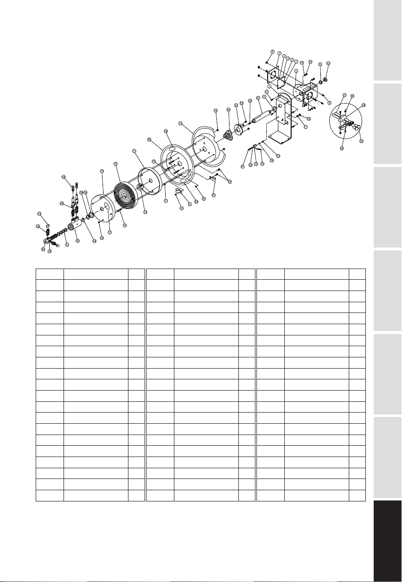
EXPLODED AND
PARTS LIST
TROUBLE
SHOOTING