(1) Pull out some hose and let reel latch.
(2) Remove the bolts that attach the guide roller bracket to the support post.
(3) Rotate guide roller bracket to correct position, replace bolts, and tighten.
3. Using the four holes in the base, mount the reel in the desired location. Be sure to use
appropriate hardware and tighten securely.
4. Apply Teflon tape or pipe sealant to supply line threads, attach to reel inlet and tighten. The
other end of incoming line can now be connected to desired supply source.
5. If hose has been supplied with reel: Apply Teflon tape or pipe sealant to outlet fitting on reel
hose, then attach to desired tool, or nozzle. Check connection for leakage, also check hose
reel for correct operation. See: Operation section.
6. If hose stopper adjustment is required, pull hose from reel and allow to latch at desired
length. Loosen stopper bolts, and slide stopper to a position close to the hose guide. Tighten
stopper bolts, and unlatch the reel.
INSTALLATION of Hose
1. Securely stabilize the reel.
2. Facing the swivel fitting side of reel: Turn the drum clockwise, by hand, until the rewind
spring is tight, and drum has latched. As an extra precaution while installing new hose,
secure drum in the latched position.
3. Insert end of the hose through guide roller bracket, and feed through the opening in the
center of the drum hub.
4. Screw fitting into swivel and tighten. Note: To avoid damage to the swivel, use a wrench to
support the swivel fitting while tightening the hose.
5. Attach hose stopper on the other end of hose, near the outlet fitting.
6. Carefully release drum latch, and slowly allow hose to wind onto the reel.
Note: Final spring tension adjustment is accomplished by adding wraps of hose around the
drum (to increase tension) or taking off wraps of hose (to decrease tension). Refer to:
Adjustment of Spring Tension.
OPERATION
1. Check reel for correct operation by slowly pulling out the hose. A “clicking” noise will be
heard every half revolution of the drum.
2. To latch the reel, pull out the hose and allow it to retract after hearing the first second or third
“ click”.
3. To unlatch, slowly pull out the hose until the “clicking” noise stops, and then let the hose
retract until the hose stop rests against the hose guide.
Note: To avoid damage to the reel, always hold on to the hose while it is rewinding.
4. Periodically check the hose condition for wear or damage, and check the swivel
fitting for leakage. Replace any worn, damaged, or leaking parts.
E2
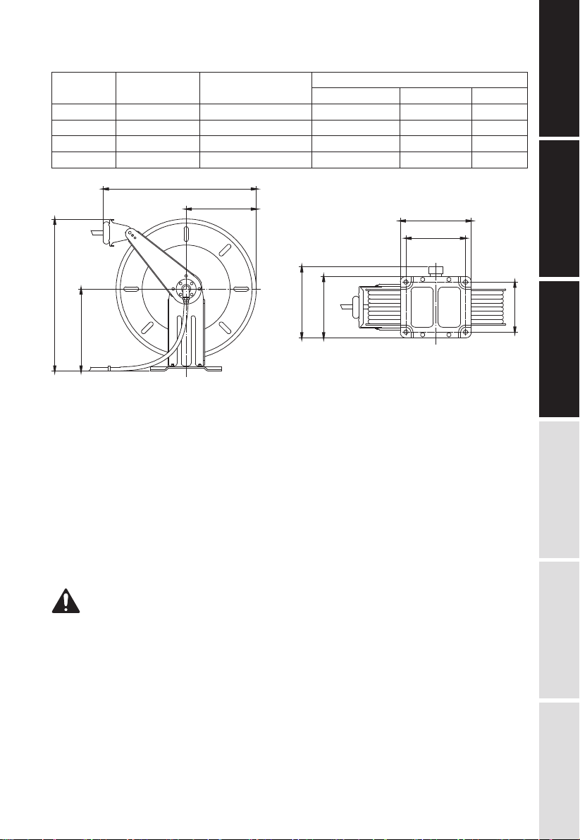
TECHNICAL
DETAILS
SAFETY
PRECAUTIONS
OPERATION
LIMITED
WARRANTY
EXPLODED AND
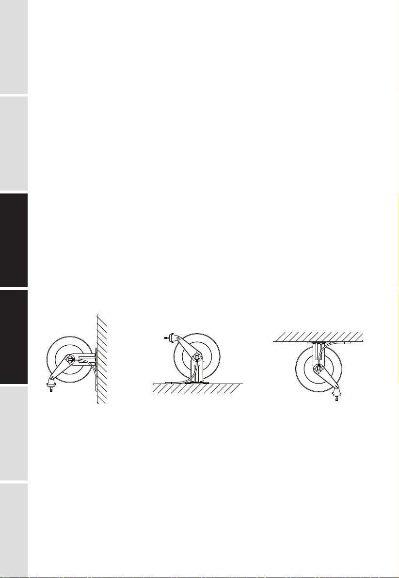
PARTS LIST INSTALLATION
Wall Floor Ceiling
Figure 2