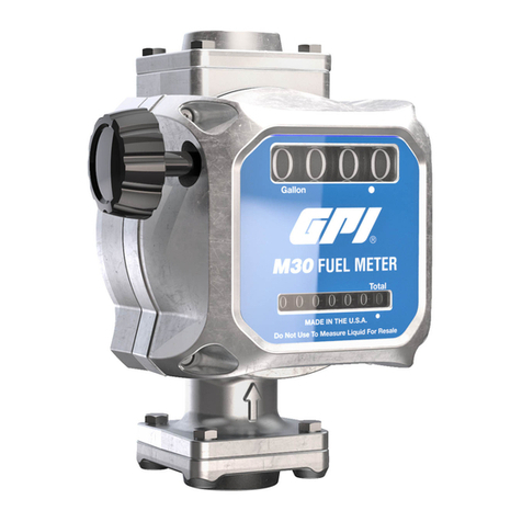
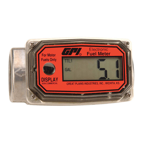
GPI MR 5-30 Series User manual

General Information....................2
Installation ..................................3
Operation....................................3
Calibration ..................................4
Maintenance...............................5
Troubleshooting..........................6
Specications .............................7
Illustrated Parts List....................8
TABLE OF CONTENTS
SAVE THESE INSTRUCTIONS
MR 5-30 or MR 5-30N Series
Fuel Meter
Owner’s Manual
To the owner…
Congratulations on receiving your GPI
MR 5-30 Meter. We are pleased to provide
you with a meter designed to give you
maximum reliability and efciency.
Ourbusinessisthedesign,manufactureand
marketingofliquidhandling,agriculturaland
recreationalproducts.Wesucceedbecause
we provide customers with innovative,
reliable, safe, timely and competitively-
priced products. We pride ourselves in
conducting our business with integrity and
professionalism.
We are proud to provide you with a quality
product and the support you need to obtain
years of safe, dependable service.
Great Plains Industries, Inc. is a member
of the Petroleum Equipment Institute.
Victor Lukic, President
Great Plains Industries, Inc

2
GENERAL INFORMATION
The purpose of this manual is to
assist you in installing, operating
and maintaining your mechanical
fuel meter. Please take a few mo-
ments to read these instructions
beforeinstallingandoperatingyour
fuel meter.
SAFETY INSTRUCTIONS
The following safety alert symbols
are used in this manual.
DANGER
DANGER indicates a hazardous
situation which, if not avoided, will
result in death or serious injury.
WARNING
WARNING indicates a hazardous
situation which, if not avoided, could
result in death or serious injury.
CAUTION
CAUTION indicates a hazardous
situation which, if not avoided, may
result in minor or moderate injury.
It is your responsibility to:
• know and follow applicable
national, state and local safety
codespertainingtoinstallingand
operatingelectricalequipmentfor
use with ammable liquids.
• know and follow all safety precau-
tions when handling petroleum
fuels
• ensure that all equipment opera-
tors have access to adequate
instructions concerning safe
operation and maintenance.
1. This meter is designed for use
only with thin viscosity petro-
leum fuels such as gasoline,
gasoline/ethanolblendsatlevels
designated as "gasohol" (E10
maximum),dieselandkerosene.
2. Do not use this equipment for
dispensing any uids other than
those for which it was designed.
To do so may damage the meter
and will void the warranty.
3. DANGER Observe precau-
tions against re or explosion
when dispensing fuel. Do not
operatethemeterinthepresence
ofanysourceofignitionincluding
running or hot engines, lighted
cigarettes, or gas or electric
heaters.
4. WARNING Any components
such as hose, nozzle, or pump
added to your meter must be
staticallygroundedandapproved
for use with petroleum fuels.
5. WARNING Avoid prolonged
skincontactwithpetroleumfuels.
Use protective goggles, gloves,
andapronsincaseofaccidental
splashing or spillage. Change
saturatedclothingandwashskin
contactareaspromptlywithsoap
and water.
The MR 5-30 Mechanical Fuel
Meter is designed for the eld mea-
surementofthinviscositypetroleum
fuelsonlyandintendedforusewith
pump systems in the 5 to 30 GPM
or 19 to 114 LPM ow range (not
intended for gravity ow systems).
Using mechanical gears, these
meters translate ow data from a
nutating disk into calibrated units
which are indicated on the face
of the meter. This meter is factory
calibratedfordieselfuel.Fieldcali-
brationfeatureisavailableforother
uids, see Calibration section.

3
FIGURE 1
INSTALLATION
Before installing your meter, review
the safety instructions given above.
Examine your meter to make sure
therearenovisiblesignsofshipment
damage.Planyour meter installation
byreviewingthefollowingprocedures.
Your system must be mounted on a
vented tank. If the tank is unvented,
your local dealer or distributor can
supply a pressure cap.
Ifthemeterislocatedinarigidpiping
system where the uid is trapped
(for example, by gravity, valves or
nozzles) thermal expansion of the
uid can create pressure spikes that
can damage a meter.
Install a thermal relief valve or oth-
erwise allow for thermal expansion
of the uid.
Prior to installation, determine the
tting angle desired and whether
horizontal or vertical orientation is
required.
Rotate Fittings
To rotate inlet and/or outlet ttings,
remove the two nuts and bolts that
secure each tting. Rotate the tting
tothedesiredorientation.Makesure
theO-ringisfullyseated.Tightenthe
nuts and bolts snugly.
C
hange Orientation
1. Pulltheknobtoremovefromunit.
Remove screws that hold bezel
in place and set aside.
2. Removethetwoscrewsthathold
thefaceplateinplaceandremove
faceplate. (Figure 1)
FIGURE 2
3. Remove two screws to release
thecounterassembly.(Figure2)
4. Removethe bevel gear from the
centerofthecoverplate.Remove
the eight pairs of nuts and bolts
thatholdthecoverplateassembly
in place.
5. Nowyoucanrotatethecoverplate
to the desired orientation. Reas-
semble in reverse order, making
sure the O-ring is fully seated.
Torque eight nuts and bolts to
60 - 72 in-lb.
Meter Installation
1. Remove protective plugs from
the meter inlet and outlet ports.
2. Wrapthreadedmaleconnections
with thread tape or use a pipe
sealant compound compatible
withpetroleumfuels.Werecom-
mend thread sealant at the inlet
tting in horizontal orientation.
3. Install the meter on the pump us-
ing an appropriately sized nipple.
The meter’s ow path is marked on
the housing exterior with an arrow
pointing toward the outlet port.
4. Installothersystemcomponents
on the meter and tighten snugly.
OPERATION
ALWAYSFOLLOWSAFETYPRE-
CAUTIONS WHEN OPERATING
THIS EQUIPMENT. REVIEW THE
SAFETY INSTRUCTIONS. Before
each use, visually check the meter
toensureitissecurelyconnectedto

4
othersystemcomponentsandthere
isnoleakage.Promptlywipespilled
fuel from the meter’s exterior and
other system components.
The large meter display represents
theBatchTotalforeachfueldelivery.
Before dispensing, reset the Batch
Total to zero by turning the knob.
(Figure 3)
owrate is used. When topping
off the calibration container, use
a quick-open and quick-close
methoduntilthemarkisreached.
4. Comparethemeterdisplaytothe
quantity in the container. If the
meter display does not register
the quantity on the container,
adjust the meter by performing
the following:
a) Gain access to the re-
cessed calibration screw
by turning the calibration
screw cover and seal coun-
terclockwise. Remove the
cover and nylon washer.
(Figure 4)
FIGURE 3
FIGURE 4
The small display represents the
CumulativeTotalofallfueldeliveries
and cannot be reset.
CALIBRATION
Themeterisaccuratelycalibratedat
the factory for use with diesel fuel.
Due to differences in viscosity and
owrates, the meter may require
recalibrationtomeasureotherfuels
or to adjust for inaccuracies.
1. Purgeairfromthemeterandfuel
system by dispensing fuel into a
container until a full ow occurs.
Close the nozzle.
2. Resetthemetercountertozeroby
turning the reset knob. (Figure 3)
3. Pumpintoagraduatedcalibration
container to a specied quantity.
For the greatest accuracy, be
sure the container is placed on
a level surface and a consistent
b) If the meter registered less
than the quantity in the
container, turn the calibra-
tion screw clockwise. If the
meter registered more than
the amount in the container,
turn the calibration screw
counterclockwise.
5. Empty the calibration container
and repeat steps 2 to 4 until the
meter registers the quantity in
the container.
6. Install the nylon washer and
calibration screw cover.

5
MAINTENANCE
The meter’s strainer should be
cleaned at regular intervals, espe-
cially when low ow is detected.
Clean or Replace Strainer
1. Removethenutsandboltsatthe
inlet tting. Remove the tting,
O-ring, and strainer.
2. Using a ne brush, clean the
strainer. Replace the strainer as
necessary.
3. Wipe clean the inlet, housing,
and O-ring groove. Coat the O-
ringwithoilorlightgrease.Make
sure the O-ring is fully seated.
Replace the strainer.
4. Position the inlet tting in the
desired orientation and tighten
thenutsandboltsto60-72in-lb.

6
TROUBLESHOOTING
Symptom Probable Cause Corrective Action
A. Meter counter does 1. Broken counter assembly. Replace counter.
not operate. (Nor-
mal fuel delivery) 2. Foreign material in counter Remove and clean counter
assembly or nutator assembly. assembly or nutator assembly.
3. Broken nutator disc pin or Install new nutator assembly.
defective nutator assembly.
4. Missing or worn bevel gear. Replace bevel gear.
B. Meter counter does 1. Clogged strainer in meter. Clean or replace strainer.
not operate.
(Little or no fuel ow) 2. Other system components Check all system components
malfunctioning. tank to nozzle for clogs and/or
malfunctions.Repairasnecessary.
3. Foreign material in nutator Remove and clean nutator
assembly. assembly.
C. Fuel leakage. 1. Leakage at counter drive shaft. Replace coverplate assembly.
2. Leakage between coverplate Remove coverplate and inspect
and housing. for damaged, missing or
incorrectly seated seal. Replace
as required.
3. Leakage at ttings. Remove ttings and inspect for
damaged, missing or incorrectly
seatedseals.Replaceasrequired.
4. Leakage at threads. Remove meter and reseal all
threaded connections with
thread tape or pipe thread
sealing compound approved
for use with ammable liquids.

7
SPECIFICATIONS
Gallon Models Litre Models
Unit of Measure U.S. Gallon Litre
Flow Range 5 to 30 GPM 19 to 114 LPM
Operating Temperature -20° F to 125° F -29° C to 52° C
Typical Accuracy ± 2% ± 2%
Type Nutating Disc Nutating Disc
Housing Material Aluminum Aluminum
Maximum Working Pressure 50 PSIG 3.4 bar
Inlet/Outlet Fitting Size 3/4"*, 1" or 1-1/2" 3/4"*, 1" or 1-1/2"
Threads NPT NPT or BSPP*
Maximum Batch Total 999.9 9999
Maximum Cumulative Total 9,999,999.9 99,999,999
Approximate Ship Weight 8.1 lbs. 3.7 kg
Maximum Dimensions: Width: 8.0 inches 20.3 cm
Height: 7.0 inches 17.8 cm
Depth: 6.0 inches 15.2 cm
*Not available on ENP model.
Note: Accuracyis factory calibrated usingdieselfuel.Field Calibration is available on allmodels.

8
ILLUSTRATED PARTS LIST
Kits and Accessories
126530-09 Seal Kit - includes one housing O-ring and two tting O-rings
126530-59 Seal Kit - ENP model
126530-08 Nutator Assembly Kit - includes hardware
126530-58 Nutator Assembly Kit - ENP model
126530-06 Bevel Gear Kit
126530-04 Gallon Counter Assembly Kit - includes counter assembly
and hardware
126530-05 Litre Counter Assembly Kit - includes counter assembly
and hardware
126530-02 GallonFaceplateKit-includesfaceplate,decalandhardware
126530-52 Gallon Faceplate Kit - ENP model
126530-03 Litre Faceplate Kit - includes faceplate, decal and hardware
126530-01 Bezel Kit -includes hardware
126530-07 Knob Assembly Kit
126530-12 Fitting Kit for 3/4-inch NPT(2 Fittings,2 Fitting O-Rings, 1
strainer and hardware)
126530-13 Fitting Kit for 3/4-inch BSPP (2 Fittings, 2 Fitting O-Rings,
1 strainer and hardware)
126530-14 Fitting Kit for 1-inch NPT, (2 Fittings, 2 Fitting O-Rings,
1 strainer and hardware)
126530-64 Fitting Kit for 1-inch NPT, ENP model
ENP model includes stainless hardware for wetted components. The housing is ENP and the
seals are Fluorocarbon instead of Nitrile.
B
C
D
A
Part No. Description
A
B
C
D
E
F
E
F
G
H
G
H
I
J

9
Kits and Accessories, continued
Kit
No. Part No.Description
I
J
126530-15 Fitting Kit for 1-inch BSPP (2 Fittings, 2 Fitting O-Rings,
1 strainer and hardware)
126530-16 Fitting Kit for 1-1/2 inch NPT (2 Fittings, 2 Fitting
O-Rings, 1 strainer and hardware)
126530-66 Fitting Kit for 1-1/2 inch NPT, ENP model
126530-17 Fitting Kit for 1-1/2 inch BSPP (2 Fittings, 2 Fitting
O-Rings, 1 strainer and hardware)
126530-67 Calibration Screw Kit - includes screw, washer O-ring
& cover
126530-10 Hardware Kit - includes O-rings, strainer, nuts & screws
126530-60 Hardware Kit - ENP model
This manual suits for next models
1
Table of contents
Other GPI Measuring Instrument manuals
Popular Measuring Instrument manuals by other brands

Teledyne Analytical Instruments
Teledyne Analytical Instruments 3020 P operating instructions

Mitutoyo
Mitutoyo ID-F125 user manual

Endress+Hauser
Endress+Hauser Liquistation CSF33 operating instructions

Sealey
Sealey TA090 instructions

Victor
Victor VC6243 user manual

Chauvin Arnoux
Chauvin Arnoux MEMO TD80 quick start