www.globalplasmasolutions.com
Power Supply Installation and Wiring
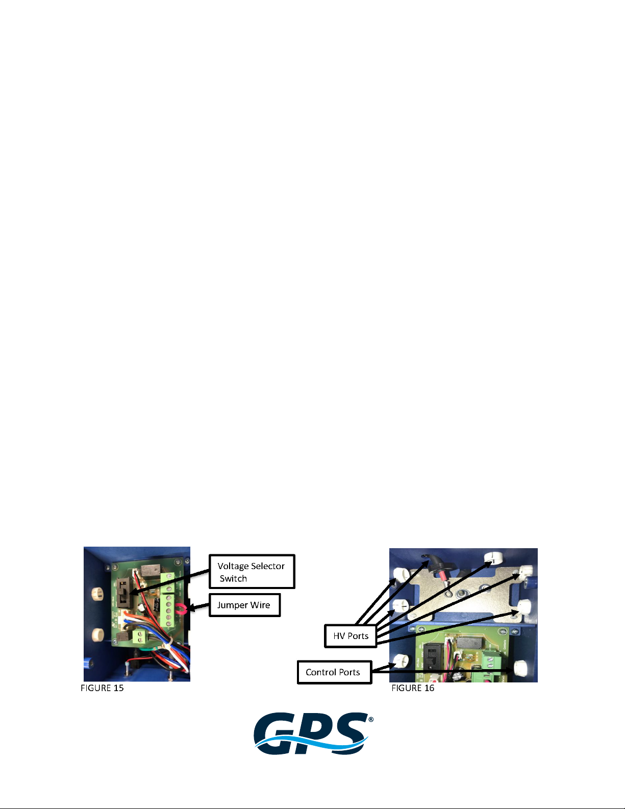
WARNING – DO NOT CONNECT POWER UNTIL VOLTAGE SELECTOR SWITCH INSIDE HOUSING IS CONFIRMED TO BE IN THE
CORRECT POSITION FOR THE PRIMARY POWER BEING APPLIED (See FIGURE 15).
The GPS-iMOD system requires a total of 15 watts to power up to 4 GPS-iMODs at any length. The power supply will
accept 24VAC, 115VAC or 208-240VAC at 50HZ or 60HZ. CAUTION!! The power supply has an internal voltage selector
switch set to 115VAC from the factory, as shown in FIGURE 15. If 24VAC or 208-240VAC is required, move the selector
switch to the proper position as shown on the circuit board or inside cover of the power supply lid. DO NOT APPLY
POWER until the switch position matches the power supplied. Based on voltage input or local codes, the 3-prong
plug may be cut o and the three wires are as follow: White = Neural, Black = 24V, 110V or 208-240V (based on switch
position) and Green = Ground. THE FACTORY ATTACHED WHITE POWER CORD MUST BE RETAINED WHERE IT
ENTERS THE iMOD POWER SUPPLY HOUSING. REMOVING THIS POWER CORD WILL VOID THE WARRANTY.
Follow all local and national electrical and building codes.
NOTE: The power supply must be grounded for all input voltages. If connecting to 24VAC power, the green grounding wire
or green grounding lug on the power supply housing must be connected to ground. A grounded common will not suce as
adequate power supply grounding.
1. The power supply may be mounted to the internal or external wall of the air handler.
2. Find a location within reach of the high voltage cable extending from the GPS-iMOD. Remove the 4 screws
securing the lid of the power supply.
3. Mount the power supply to the wall using sheet metal screws through the mounting tabs on the power
supply.
4. One HV port in the high voltage (HV) section will be left open for attachment of the HV supply wire. Refer
to FIGURE 16. Based on the jobsite specic wiring route, access to the right, left or top side may be desired.
Remove the plug from the port desired and ll the port not used with the spare plug. DO NOT RUN
HIGH VOLTAGE INPUT WIRES THROUGH THE CONTROL PORTS AND DO NOT RUN CONTROL WIRING
THROUGH HIGH VOLTAGE (HV) PORTS! REFER TO FIGURE 16.
5. Remove the top nut from the HV screw (FIGURE 17). DO NOT REMOVE THE BOTTOM NUT! Remove the plastic
nut (FIGURE 18) from the end of the high voltage cable. Next, push the HV wire through the desired port and
place the plastic nut back over the HV cable. Place the electrical eye connector over the HV screw and tighten
down the top nut to secure. If there are multiple bars connected, place all electrical eye connectors under the
top nut prior to tightening. Push the HV connector into the HV port and tighten the plastic nut to secure in
place (FIGURE 19). Once all connections are made, replace lid or proceed to connect the control wiring.