Graco 115123 Datasheet

Instructions-Parts List
Lubrication
Controller, 24V
Used to control and monitor automatic lubrication systems. For professional use only.
Not for use in explosive atmospheres.
Part No. 115123
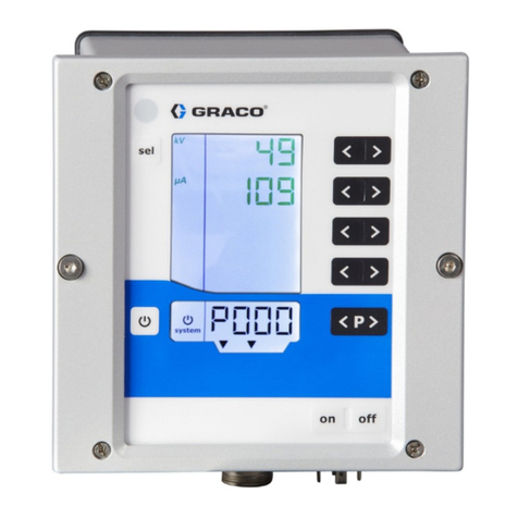
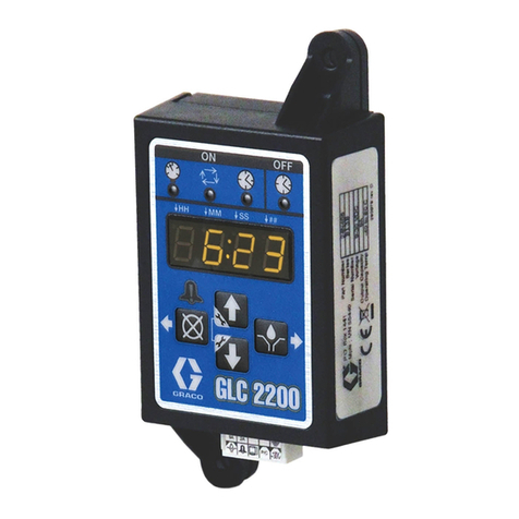
This Lubrication Controller is designed to control and monitor most single–line parallel automatic lubrication systems.
All configuration parameters are electronically stored in a System Set–Up Menu and a Time Menu (see page 7),
which eliminates the need to set dip switches or jumpers.
Table of Contents
Warnings . . . . . . . . . . . . . . . . . . . . . . . . . . . . . . . . . . . 2
Installation . . . . . . . . . . . . . . . . . . . . . . . . . . . . . . . . . . 4
Setup . . . . . . . . . . . . . . . . . . . . . . . . . . . . . . . . . . . . . . 6
Operation. . . . . . . . . . . . . . . . . . . . . . . . . . . . . . . . . . . 8
Alarm Codes . . . . . . . . . . . . . . . . . . . . . . . . . . . . . . . . 8
Troubleshooting . . . . . . . . . . . . . . . . . . . . . . . . . . . . . . 9
Accessories and Kits . . . . . . . . . . . . . . . . . . . . . . . . . . 9
Technical Data. . . . . . . . . . . . . . . . . . . . . . . . . . . . . . 10
Dimensions . . . . . . . . . . . . . . . . . . . . . . . . . . . . . . . . 10
Mounting Hole Layout . . . . . . . . . . . . . . . . . . . . . . . . 10
Graco Standard Warranty . . . . . . . . . . . . . . . . . . . . .12
Graco Information . . . . . . . . . . . . . . . . . . . . . . . . . . . 12
Important Safety Instructions
Read all warnings and instructions in this
manual. Save these instructions. Also
see system manual 309015
8852A
308950C
ENG
C3001IE

Symbols
2308950C
Symbols
Warning Symbol
This symbol alerts you to the possibility of serious injury or death if youdo not follow the instructions.
This symbol alerts you to the possibility of serious injury
or death if you do not follow the instructions.
Caution Symbol
This symbol alerts you to the possi bility of serio us injury or dea th if you do not follow the instruc tions.
This symbol alerts you to the possibility of damage to or
destruction of equipment if you do not follow the
instructions.
WARNING CAUTION
WARNINGWARNINGWARNING
WARNING
INSTRUCTION
S
EQUIPMENT MISUSE HAZARD
• Disconnect the power before servicing and before you remove the cover.
• Do not touch electrical components inside the Lubrication Controller; you could get an electric shock
or damage the circuits.
• This equipment is for professional use only.
• Read all instruction manuals, tags, and labels before operating the equipment.
• Use the equipment only for its intended purpose. If you are not sure, call your Graco distributor.
• Do not alter or modify this equipment. Use only genuine Graco parts and accessories. Modifying
parts can cause a malfunction and result in serious bodily injury.
• Check equipment daily. Repair or replace worn or damaged parts immediately.
•Connect to a proper electrical power source. See the Technical Data section on page 10.
•Comply with all applicable local, state, and national fire, electrical, and safety regulations.
• Use only alarm and control devices that are compatible with the electrical requirements of this unit.

Installation
308950C 3
Installation
The installation shown in Fig. 1 is only a guide for selecting and installing system components. Contact your Graco
distributor for assistance in planning a system to suit your needs.
Key:
A Main air supply
B Filter/Regulator/Lubricator assembly
B1 Filter
B2 Regulator
B3 Lubricator
C Air solenoid valve
D Pump module
E Ignition switch
G High-pressure lubricant supply lines
H Injector banks
J Lubrication controller
FIG. 1: Typical Installation _____________________________________________________________________
A
B1 B2 B3 C
D
GHH
J
8853A
E
Low Reservoir
Level Switch
User Provided
Pressure Switch
For System Control
Remote Alarm Device
(Light or Horn)
User Provided
Optional 1 amp
fused line for
Remote Alarm Device
24V
Battery
Controller Capabilities

Installation
4308950C
Installation
Installing the Lubrication Controller
1. Select a flat surface upon which to install the Lubri-
cation Controller, and drill mounting holes according
to the Mounting Hole Layout on page 10.
2. Remove Lubrication Controller cover, and secure
the junction box using four #6 screws (not provided).
3. Connect solenoid valve leads to terminals 4(-) and
6(+) (output).
4. Fig. 2. Step optional for use of external alarm.
Terminals 7 and 8 are a normally open, voltage–free
switch, available as a switching device for an exter-
nal alarm circuit. Connect fused (+) power supply
(not supplied) to terminal 8. Connect terminal 7 to
external alarm. Ground external alarm to complete
circuit.
5. This step is optional.
Connect terminals 9 and 11 to a normally–open
pressure switch installed in system lubricant supply
line for pressure–controlled system shutdown.
NOTE: The pressure switch, upon detecting the pre-
set pressure, will send a signal to the Lubrication
Controller to deactivate the air solenoid valve, which
will deactivate the pump.
6. This step is optional.
Connect terminals 12 and 13 to a normally–open
low–level switch (user provided).
NOTE: Upon detection by a low–level sensor, the
Lubrication Controller will activate the alarm condi-
tion.
7. This step is optional
Connect terminals 14 and 15 to a normally open
switch. Closing of the switch will suspend Lubrica-
tion Controller operation. Reopening of the switch
will resume Lubrication Controller function from the
point at which operation was suspended.
8. Connect the power leads from an isolated power
supply. Connect terminal 3 to the negative (-) lead
(ground), and connect terminal 2 to the positive (+)
lead.
9. Replace the Lubrication Controller cover.
CAUTION
This Lubrication Controller is not designed to be
operated in a caustic environment
CAUTION
Use only the pre-drilled holes under the cover fas-
teners to mount the timer. Failure to use the desig-
nated mounting holes could cause circuit board
damage.
CAUTION
Do not ground any lead for the pressure switch or
the low level switch. Circuit board damage may
result.
FIG. 2_______________________________________
8855A
24V
max.
Light
1-amp Fuse
External
Alarm Device
24V 1 amp. max.
CAUTION
If using the low level indication feature, the lubrica-
tion controller will remain in alarm mode and will not
function until the low level switch is opened by refill-
ing the fluid reservoir. Failure to correct the low level
condition will result in interruption of the automatic
lube system which could lead to premature bearing
failure.
AUTOMATIC SYSTEM ACTIVATION
Do not connect power to timer if the pump power
supply is on, unless activation of the automatic lubri-
cation system is intended. This device is an auto-
matic timing device that activates the output circuit
(air solenoid valve) upon power connection or upon
exit of the programming function. Ignoring this warn-
ing could lead to serious injury including fluid injec-
tion and amputation due to activation of connected
system components.
Installation
308950C 5
Electrical Connections and Circuit Details
ELECTRIC SHOCK HAZARD
Before you install or remove the Lubrication Control-
ler from the system, disconnect and isolate all power
supplies.
CAUTION
110 volt and 220 volt power is not supported at this
time.
8855A
8854A
See diagram below for
terminal identification.
Optional circuit (if using
remote alarm)
Ignition Switch
24V
Battery
External
Alarm
24V
1 Amp.
Max.
24V Air
Solenoid
Black indicates not used
Optional Devices
Normally
Open
Pressure
Switch
Normally
Open
Fluid Level
Switch
Suspend Timer
Device (Ignition Switch)
Open Circuit=Timer
Functions
Closed Circuit
Timer is Suspended
1 A Fuse

Setup
6308950C
Setup
PUMP ON light: Indicates that the Lubrication Controller is in the Pump On mode, and the device (air solenoid valve)
connected to terminals 4 and 6 should be receiving power.
Display: TIMER light on: Display indicates time remaining in hours and minutes until the next Pump On cycle.
PUMP ON light on: Display indicates time remaining in minutes and seconds in the Pump On cycle.
ALARM light on: Display indicates alarm codes (see page 8).
INDICATOR lights flashing: Display indicates that the Lubrication Controller is counting down to
the next Pump On cycle.
INDICATOR lights steady: Display indicates that the Lubrication Controller is in Suspended
mode, activated by contacts 14 and 15 being close–circuited.
TIMER light: Indicates that the Lubrication Controller is in Timer mode.
UP button: For toggling between options in the System Set–Up Menu. Press this button and the DOWN button at the
same time to enter the System Set–Up Menu.
TIME button: For advancing to the next option in the Time Menu.
DOWN button: For adjusting settings in the Time Menu. Press this button and the UP button at the same time to
enter the System Set–Up Menu.
POWER light: Indicates that power to the Lubrication Controller is on.
RESET button: For resetting an alarm malfunction. Resets to the start of a lube cycle -- pushing this button activates
Lubrication Controller to open solenoid and start pump. Will activate a manual lube cycle and resets pause interval.
LOW LEVEL light: Indicates that the reservoir fluid level is low.
ALARM light: Indicates that an alarm is activated.
8858A
Pump ON light
Display
TIMER light
UP button
TIME button
DOWN button
POWER light
INDICATOR light
ALARM light
LOW LEVEL light
RESET button

Setup
308950C 7
Setup
System Set-Up Menu
The System Set–Up Menu is used to configure the type of pump and automatic lubricating system that is connected
to the Lubrication Controller. The modes in the System Set–Up Menu progress in the order shown in the table below.
To access the System Set–Up Menu, press the UP and DOWN buttons simultaneously, and hold them down for two
seconds.
Time Menu
The Time Menu is used to adjust the Pump On cycle and Pause Interval. The modes in the Time Menu progress in
the order shown in the table below.
To access the Time Menu, press and hold the TIME button for two seconds.
AUTOMATIC SYSTEM ACTIVATION
Do not connect power to timer if the pump power
supply is on, unless activation of the automatic lubri-
cation system is intended. This device is an auto-
matic timing device that activates the output circuit
(air solenoid valve) upon power connection or upon
exit of the programming function. Ignoring this warn-
ing could lead to serious injury including fluid injec-
tion and amputation due to activation of connected
system components.
Parameter Description Screen Display Operation
Lubrication system
type
Pressure–switch–controlled on
single–line systems Press the UP button to toggle
between the two options.No pressure–switch–control,
just timer
Press the TIME button to accept the change. Press the RESET button to cancel the change.
Parameter Description Screen Display Operation
Pump On time Indicates the minimum
Pump On time in
minutes : seconds
Maximum: 59:50
Minimum: 00:10
Pump ON light flashing
Press the UP and DOWN buttons
to adjust the setting.
Press and hold the TIME button for two seconds to advance to the next option.
Pause interval Indicates the Pause Interval
between lubrication cycles in
hours : minutes
Maximum: 99:59
Minimum: 00:01
TIMER light flashing
Press the UP and DOWN buttons
to adjust the setting.
Press and hold the TIME button for two seconds to advance to the next option.

Operation
8308950C
Operation
1. Connect power to Lubrication Controller
2. See Setup on page 7 for Lubrication Controller pro-
gramming.
3. Open air supply to air solenoid valve.
4. Activate power to Lubrication Controller to initiate
Pump On cycle. Ensure that PUMP ON light and
POWER light are on and the pump is operational.
5. Ensure that POWER light and TIMER light are on
after Pump On cycle is complete.
Lubrication Controller will automatically activate the
system at programmed intervals.
6. Power will be removed from properly wired system
upon turning off ignition key.
7. To disable automatic lube system, turn off air supply
to solenoid and/or pump.
Alarm Codes
The Lubrication Controller self diagnoses when it is powered up, and alarm codes are shown in the display during
fault conditions. These alarm codes are explained in the table below.
NOTE: for automatic lube system troubleshooting, see manual 309015.
AUTOMATIC SYSTEM ACTIVATION
Do not connect power to timer if the pump power
supply is on, unless activation of the automatic lubri-
cation system is intended. This device is an auto-
matic timing device that activates the output circuit
(air solenoid valve) upon power connection or upon
exit of the programming function. Ignoring this warn-
ing could lead to serious injury including fluid injec-
tion and amputation due to activation of connected
system components.
Alarm Code Description Corrective Action
A01 No parameters set. Set the parameters of the system. See Setup
on page 7.
A02 Level of lubricant is low in the supply container.
Lubrication Controller will not function until the
fluid reservoir is filled.
Add lubricant to the supply container.
NOTE: This alarm requires that your system
has a low–level switch installed.
A04
(PSI mode only)
The system pressure was already high before
the start of the cycle.
Check pressure switch and replace if neces-
sary.
Check to see if system vents properly.
A05
(PSI mode only)
PSI mode: The system did not achieve pressure
during the specified cycle times.
1. Pump On setting for system is too short.
2. Out of lubricant.
3. Broken supply line.
4. Injector malfunction.
5. Pump malfunction.
6. Vent valve malfunction.
Check for and correct lubricant leakage from
any loose fittings or from the pump.
Adjust setting as appropriate. See Time Menu
on page 7.
Fill reservoir.
Fix or replace.
Replace.
Refer to Pump Manual 308883.
Fix or replace.

Troubleshooting
308950C 9
Troubleshooting
Accessories and Kits
Repair Kit 241574
Repair Kit 241574 is available. It contains two junction
box connectors and six rubber grommets, as shown.
24V Air Solenoid 114488
Pressure Switch 115124
Description Problem Solution
Timer fails to activate solenoid No power supplied to solenoid
Solenoid faulty
Timer faulty
Low Level alarm
Power light off: timer is not receiving power.
Verify connections and verify power supply
Power light on: verify solenoid connections
Replace solenoid
Replace timer
Refill reservoir
Pressure switch fails to shut
down system2
Pressure switch incorrectly wired
Pressure switch faulty
Timer faulty
Verify proper connections
Replace pressure switch
Replace timer
8856A
9008A
3/8” npt (3)
Manual
Activation
Button
9146A 1/4” npt(f)

Technical Data
10 308950C
Technical Data
Dimensions Mounting Hole
Layout
Input Contacts
Power . . . . . . . . . . . . . . . . . . . . . . . . . . . . . . . . . . . . . . . . . . . . . . . . . . . . . . . . . . . . . . . . . . . . . . . . . . . 24V D.C.
Power consumption. . . . . . . . . . . . . . . . . . . . . . . . . . . . . . . . . . . . . . . . . . . . . . . . . . . . . . . . . . . . . . . . . . 20 Watts
Control input (optional) . . . . . . . . . . . . . . . . . . . . . . . . . . . . . . . . . . . . . . . . . . . . . Normally open pressure switch
Lubrication level (optional) . . . . . . . . . . . . . . . . . . . . . . . . . . . Normally open level switch, closes upon low level
Outputs
Air solenoid valve (pump control) . . . . . . . . . . . . . . . . . . . . . . . . . . . . . . . . . . . . . . . . . . . . . . . . . . . . . . 24V D.C.
Alarm switch, normally open (optional) . . . . . . . . . . . . . . . . . . . . . . Voltage–free contact, 250V maximum, 1 amp
Protection grade . . . . . . . . . . . . . . . . . . . . . . . . . . . . . . . . . . . . . . . . . . . . . . . . . . . . . . . . . . . . . . . IP55, Nema 12
Operating temperature range . . . . . . . . . . . . . . . . . . . . . . . . . . . . . . . . . . . . . . -13° F to 131° F (-25° C to 55° C)
8852A
8852A
5.2 in.
(132 mm)
5.2 in.
(132 mm)
2.4 in.
(60 mm)
8857A
Drill four
0.14-in.
(3.5-mm)
holes. 3.74 in.
(95 mm)
3.74 in.
(95 mm)

Technical Data
308950C 11

All written and visual data contained in this document reflects the latest product information available at the time of publication.
Graco reserves the right to make changes at any time without notice.
This manual contains English. MM 308950
Graco Headquarters: Minneapolis
International Offices: Belgium, China, Japan, Korea
GRACO INC. P.O. BOX 1441 MINNEAPOLIS, MN 55440-1441
Copyright 1999, Graco Inc. is registered to ISO 9001
www.graco.com
Revised 12/2009
Graco Standard Warranty
Graco warrants all equipment referenced in this document which is manufactured by Graco and bearing its name to be free from defects in
material and workmanship on the date of sale to the original purchaser for use. With the exception of any special, extended, or limited warranty
published by Graco, Graco will, for a period of twelve months from the date of sale, repair or replace any part of the equipment determined by
Graco to be defective. This warranty applies only when the equipment is installed, operated and maintained in accordance with Graco’s written
recommendations.
This warranty does not cover, and Graco shall not be liable for general wear and tear, or any malfunction, damage or wear caused by faulty
installation, misapplication, abrasion, corrosion, inadequate or improper maintenance, negligence, accident, tampering, or substitution of
non-Graco component parts. Nor shall Graco be liable for malfunction, damage or wear caused by the incompatibility of Graco equipment with
structures, accessories, equipment or materials not supplied by Graco, or the improper design, manufacture, installation, operation or
maintenance of structures, accessories, equipment or materials not supplied by Graco.
This warranty is conditioned upon the prepaid return of the equipment claimed to be defective to an authorized Graco distributor for verification of
the claimed defect. If the claimed defect is verified, Graco will repair or replace free of charge any defective parts. The equipment will be returned
to the original purchaser transportation prepaid. If inspection of the equipment does not disclose any defect in material or workmanship, repairs will
be made at a reasonable charge, which charges may include the costs of parts, labor, and transportation.
THIS WARRANTY IS EXCLUSIVE, AND IS IN LIEU OF ANY OTHER WARRANTIES, EXPRESS OR IMPLIED, INCLUDING BUT NOT LIMITED
TO WARRANTY OF MERCHANTABILITY OR WARRANTY OF FITNESS FOR A PARTICULAR PURPOSE.
Graco’s sole obligation and buyer’s sole remedy for any breach of warranty shall be as set forth above. The buyer agrees that no other remedy
(including, but not limited to, incidental or consequential damages for lost profits, lost sales, injury to person or property, or any other incidental or
consequential loss) shall be available. Any action for breach of warranty must be brought within two (2) years of the date of sale.
GRACO MAKES NO WARRANTY, AND DISCLAIMS ALL IMPLIED WARRANTIES OF MERCHANTABILITY AND FITNESS FOR A
PARTICULAR PURPOSE, IN CONNECTION WITH ACCESSORIES, EQUIPMENT, MATERIALS OR COMPONENTS SOLD BUT NOT
MANUFACTURED BY GRACO. These items sold, but not manufactured by Graco (such as electric motors, switches, hose, etc.), are subject to
the warranty, if any, of their manufacturer. Graco will provide purchaser with reasonable assistance in making any claim for breach of these
warranties.
In no event will Graco be liable for indirect, incidental, special or consequential damages resulting from Graco supplying equipment hereunder, or
the furnishing, performance, or use of any products or other goods sold hereto, whether due to a breach of contract, breach of warranty, the
negligence of Graco, or otherwise.
FOR GRACO CANADA CUSTOMERS
The Parties acknowledge that they have required that the present document, as well as all documents, notices and legal proceedings entered into,
given or instituted pursuant hereto or relating directly or indirectly hereto, be drawn up in English. Les parties reconnaissent avoir convenu que la
rédaction du présente document sera en Anglais, ainsi que tous documents, avis et procédures judiciaires exécutés, donnés ou intentés, à la suite
de ou en rapport, directement ou indirectement, avec les procédures concernées.
Graco Information
For the latest information about Graco products, visit www.graco.com.
TO PLACE AN ORDER, contact your Graco distributor or call to identify the nearest distributor.
Phone: 612-623-6928 or Toll Free: 1-800-533-9655, Fax: 612-378-3590
Table of contents
Other Graco Controllers manuals

Graco
Graco Series B Operation manual

Graco
Graco 214706 User manual

Graco
Graco Series B Operation manual

Graco
Graco 217075 Operation manual

Graco
Graco 238889 Operation manual

Graco
Graco SERIES F Operation manual

Graco
Graco 24E025 Operation manual

Graco
Graco LC0250 Parts list manual

Graco
Graco Xtreme-Wrap 26C930 User manual

Graco
Graco 24W482 User manual

Graco
Graco Reactor 2 H-30 Operating instructions

Graco
Graco Series A User manual

Graco
Graco 237160 User manual

Graco
Graco GLC 4400 User manual

Graco
Graco Series B User manual

Graco
Graco C Series User manual

Graco
Graco Series A Parts list manual

Graco
Graco Harrier EZ-Batch User manual

Graco
Graco Matrix PAC 247436 User manual

Graco
Graco GLC 2200 User manual