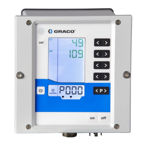
Graco GLC 4400 User manual

Instructions
GLC 4400
Lubrication Controller 313855K
For controlling and monitoring single-line resistive, parallel, series progressive and dual
line, automatic lubrication systems. Not for use in explosive atmospheres!
Part No.: 24B591, Series E: DC Power
Part No.: 24B596, Series E: AC Power
Important Safety Instructions
Read all warnings and instructions in this
manual. Save these instructions.
ti14059
EN

Warnings
2313855K
Warnings
The following warnings are for the setup, use, grounding, maintenance, and repair of this equipment. The exclama-
tion point symbol alerts you to a general warning and the hazard symbol refers to procedure-specific risk. Refer back
to these warnings. Additional, product-specific warnings may be found throughout the body of this manual where
applicable.
WARNING
ELECTRIC SHOCK HAZARD
This equipment must be grounded. Improper grounding, setup, or usage of the system can cause
electric shock.
• Turn off and disconnect power at main switch before disconnecting any cables and before servicing
equipment.
• Connect only to grounded power source.
• All electrical wiring must be done by a qualified electrician and comply with all local and national
codes and regulations.
EQUIPMENT MISUSE HAZARD
Misuse can cause death or serious injury.
• Do not operate the unit when fatigued or under the influence of drugs or alcohol.
• Do not exceed the maximum working pressure or temperature rating of the lowest rated system
component. See Technical Data in all equipment manuals.
• Check equipment daily. Repair or replace worn or damaged parts immediately with genuine manu-
facturer’s replacement parts only.
• Do not alter or modify equipment.
• Use equipment only for its intended purpose. Call your distributor for information.
• Route hoses and cables away from traffic areas, sharp edges, moving parts, and hot surfaces.
• Do not kink or over bend hoses or use hoses to pull equipment.
• Keep children and animals away from work area.
• Comply with all applicable safety regulations.

Component Identification
313855K 3
Component Identification
Keypad, Display, and Icons
Run Mode Functions
Direction Arrows
A Up and Down Arrow Keys: Adjusts contrast.
B Left and Right Arrow Keys: Adjusts brightness.
• Press the LEFT and RIGHT ARROW keys
simultaneously to manually start a pump cycle.
Keypad Icons
NOTE: Keypad Icons are described on Icon’s page 4.
C ENTER Key: Press and hold for 3 seconds. Allows
access to setup.
D RESET Key: Press and hold for 3 seconds. Resets
unit to normal Pump Off state. Also is used to reset
an alarm condition.
E FUNTION LED: See page 4 for a description of
these icons.
F DISPLAY
FIG. 1
!
A
B
C
D
E
F

Component Identification
4313855K
Icon Definitions
The following icons are used throughout this instruction manual and on the Controller’s Run and Setup Screens.
Refer to this table if you are unsure of an Icon’s meaning.
*See Field E, page 3 for location of these Function Icons.
Power on indicator*. When power is supplied to the Lubrication Controller, Green LED illuminates under Function Icon
located above display screen.
Pump On indicator*. When Pump On is running, Yellow LED illuminates under Function Icon located above display
screen. Icon also is displayed on top left side of Prelube Run screens (see page 37).
Pump Off indicator. When Pump Off is running, icon is displayed on top left side of Run screens (see page 38).
Alarm event activated. LED illuminates when an Alarm event occurs. Icon also displays on top right side of Alarm
screen (see page 40).
Brightness adjustment. Use the LEFT/RIGHT Arrow key to adjust display backlight (brighter or darker) (see page 20).
Contrast adjustment. Use the UP/DOWN Arrow key to adjust screen contrast (see page 20).
Low Level Alarm. Icon appears on display screen. Indicates the lubrication fluid level is low.
Change Icon. When icon appears on PIN setup screen, indicates changes can be made to PIN number or new PIN
number can be added.
Lock Icon. Indicates the Setup screens are password protected and require the user to provide the correct PIN number
to access this feature.
Setup mode active. When user is on the Main Setup Screen in the Setup Mode, icon displays on the upper right corner
of the display screen.
Timer mode activated. Displays on right side of screen when a Timer Setup or Run screen is displayed (pages 24, 27,
37 and 38).
Pressure mode activated. Icon displays on right side screen when a Pressure Setup or Run screen is displayed (page
25 and 37).
Pressure mode error. Icon displays on alarm screen to signal the allotted time ran out before the pressure switch was
tripped.
Cycle count mode active*. Yellow LED illuminates under Function Icon located above display screen. Icon also appears
on right side of display screen when a Cycle Setup or Run screen is displayed (page 25 and 38).
Machine count active. Displays on right side of Setup or Run screen when a Machine Count screen is displayed (page
27 and 39).
Machine count error. When icon displays on alarm screen, indicates the set number of machine counts was not
received before time expired (page 39). This would trigger an alarm event.
Cycle switch input error. Icon displays in center of Alarm screen to indicate the allotted time ran out before the
programmed number of cycle switch activations was received (see Alarm Screen, page 40).
Alarm*. Red LED illuminates under symbol located above display screen. Icon also appears on display when no valid
run values have been entered.

Installation
313855K 5
Installation
Typical Installation
The installation shown in FIG. 2 is only a guide for selecting and installing system components. Contact your Graco
distributor for assistance in planning a system to suit your needs.
A Main Air Supply
B Filter/Regulator/Lubricator Assembly
B1 - Filter
B2 - Regulator
B3 - Lubricator
C Air Solenoid Valve
D Pump Module
E Ignition Switch
F High-Pressure Lubricant Supply Lines
G Injector Banks
H Lubrication Controller
J Model 24B591 12/24VDC Power Supply
K Model 24B596 115/230VAC Power Supply
FIG. 2
Controller
Capabilities
!
B1 B2 B3 C
EH
GF
D
Low Reservoir Level
switch (user provided)
Pressure or Cycle Switch
for system control
(user provided
Machine Counts for
System Control
(user provided)
Pressure Switch or Cycle
Switch Alarm
Low Level Alarm
Remote Alarm Device
(Light or Horn)
(user provided)
A
K
J

Installation
6313855K
Installing the Lubrication Controller
1. Select a flat surface to install the Lubrication Con-
troller. Drill mounting holes. Refer to Mounting Hole
Layout provided in the Technical Data section of this
manual, page 42.
2. Remove Lubrication Controller cover and align junc-
tion box with predrilled holes (FIG. 3, (a). Use four,
#6 screws (not provided) to secure junction box to
mounting surface.
*Parts not supplied. To maintain IP69K rating, proper
connectors must be used.
Grounding
The equipment must be grounded. Grounding reduces
the risk of static and electric shock by providing an
escape wire for the electrical current due to static build
up or in the event of a short circuit.
1. Loosen M6 screws from (b).
2. Attach up to 3 ground wires to (b) using appropriate
sized M6 ring terminal (not provided).
3. If more than 3 wires are used, attach necessary
amount of jumpers to other adjacent screw termi-
nals.
AUTOMATIC SYSTEM ACTIVATION HAZARD
Unexpected activation of the system could result in seri-
ous injury, including skin injection and amputation.
This device has an automatic timer that activates the
pump lubrication system when power is connected or
when exiting the programming function. Before you
install or remove the Lubrication Controller from the
system, disconnect and isolate all power supplies and
relieve all pressure.
NOTICE
Pre-drill and use designated mounting holes in Lubrica-
tion Controller box only. Failure to use designated
mounting holes can cause circuit board damage.
FIG. 3
aa
aa
*
FIG. 4
b
jumper motor ground
sensor ground
ground

Installation
313855K 7
System Configuration and Wiring
The System Configuration Diagrams (FIG. 5 - FIG. 7),
Sensor Wiring Diagrams (FIG. 8 - FIG. 10) and Wiring
Diagrams (FIG. 11 - FIG. 16) on the following pages,
show typical Injector, Divider Valve and Dual Line lubri-
cation system configurations.
Refer to Table 1, 2 and 3 to determine the Required Sys-
tem Configuration, Sensor Configuration and Wiring
Diagram to use to setup your system.
Table 4 shows additional (optional) setup configurations
(FIG. 17 - FIG. 19).
Table 1: System Configurations
Table 2: Sensor Wiring Configurations
Table 3: Modes of Operation
Table 4: Optional I/O Wiring Diagrams
System Figure Page
Divider Valve 5 8
Dual Line 6 9
Injector 7 10
Sensor Figure Page
Dry Contact 8 11
Sourcing 9 11
Sinking 10 11
Mode Power Figure Page
Time ON/Time OFF DC 11 12
Time ON/Time OFF AC 12 12
Cycle ON or Pressure
ON/Time OFF DC 13 13
Cycle ON or Pressure
ON/Time OFF AC 14 13
Cycle ON or Pressure
ON/Machine Count
OFF
DC 15 14
Cycle ON or Pressure
ON/Machine Count
OFF
AC 16 14
System Mode Power Supply Wiring
Diagram
Low Level Switch FIG. 17, page 15
External Manual Run FIG. 17, page 15
O.K. Contact Out FIG. 17, page 15
Auxiliary and Low
Level Alarm Out
DC: FIG. 18, page 16
115/230 VAC: FIG. 19, page
16

Installation
8313855K
System Configuration
FIG. 5
GLC 4400
External
Low Level
Alarm
Remote
Manual Run
Machine
Count Switch
Low Level
Switch
Pump
Reservoir
Master Divider Valve
Secondary Divider Valves
Cycle
Switch
Divider Valve System
External O.K.
Pump On/Off
External
Alarm
Cycle
Machine
Count

Installation
313855K 9
FIG. 6
GLC 4400
External
Alarm
Cycle
Machine
Count
External
Low Level
Alarm
External O.K.
Low Level
Switch
Pump
Reservoir
Dual Line System
Cycle
Switch
Bi-flo
Valves
Lubrication Points
Vent
Line
Pump On/Off
Reverser
Remote
Manual Run
Machine
Count Swtich

Installation
10 313855K
FIG. 7
GLC 4400
External
Low Level
Alarm
Remote
Manual Run
Machine
Count Switch
Low Level
Switch
Pump
Reservoir
Injector System
Pressure
Switch
Injectors
Lubrication Points
Vent
Line
Pump On/Off
External O.K. External
Alarm
Cycle
Machine
Count

Installation
313855K 11
System Wiring
NOTE:
• On an AC controller (p/n 24B596), the J7 strip is line (input) voltage but the J6 strip is all 24VDC. On a DC con-
troller (p/n 24B591), the J6 and J7 terminals all carry the input voltage.
• SEN (x) jumper must be field installed.
Input Sensor Wiring:
DRY CONTACT SWITCH
SOURCE SWITCH - 2 or 3 Wire Type
SINK SWITCH - 2 or 3 Wire Type
NOTICE
Do not connect any of the SW+ (13,9,5,1) and SW-
(16,12,8,4) pins together, either directly or via a
switch closure. Doing so will create a short circuit
condition which will disable and potentially damage
the controller.
FIG. 8
FIG. 9
x = sensor input 1,2,3 or 4
1 (SW +)
2 (IN (x))
3 (SEN (x))
4 (SW -)
J6
1 (SW +)
4 (SW -)
J6
x = sensor input 1,2,3 or 4
2 (IN (x))
3 (SEN (x))
FIG. 10
1 (SW +)
4 (SW -)
x = sensor input 1,2,3 or 4
2 (IN (x))
3 (SEN (x))
J6

Installation
12 313855K
Pump ON = Time; Pump OFF = Time
9 - 30VDC
100VAC/240VAC
FIG. 11 *Dry Contact, FIG. 8 shown. For other configuration, see FIG. 9 or FIG. 10.
16 (SW-)
15 (SEN4)
14 (IN4)
13 (SW+)
12 (SW-)
11 (SEN3)
10 (IN3)
9 (SW+)
8 (SW-)
7 (SEN2)
6 (IN2)
5 (SW+)
4 (SW-)
3 (SEN1)
2 (IN1)
1 (SW+)
1(IN)
2(COM)
3(OUT1)
4(COM)
5(OUT2)
6(COM)
7(OUT3)
8(COM)
9(OUT4)
10(OUT4)
11
OUTPUTS -PWR+
J6J7
Air Solenoid
+
+
(Voltage =Battery Voltage)
Pump Solenoid
Ignition Switch
9 - 30 VDC Battery
Manual
Low
Level
Press/
Cycle Count
5A max.
NC
FIG. 12
16 (SW-)
15 (SEN4)
14 (IN4)
13 (SW+)
12 (SW-)
11 (SEN3)
10 (IN3)
9 (SW+)
8 (SW-)
7 (SEN2)
6 (IN2)
5 (SW+)
4 (SW-)
3 (SEN1)
2 (IN1)
1 (SW+)
1(IN)
2(COM)
3(OUT1)
4(COM)
5(OUT2)
6(COM)
7(OUT3)
8(COM)
9(OUT4)
10(OUT4)
11
OUTPUTS -PWR+
J6J7
Air Solenoid
Ignition Switch
Manual
Low
Level
Press/
Cycle Count
100-240 VAC
(Voltage =Line Voltage)
Pump Solenoid
10A max.
NC

Installation
313855K 13
System Wiring
Pump ON = Cycle or Pressure; Pump OFF = Time
9 - 30VDC
100VAC/240VAC
FIG. 13 *Dry Contact, FIG. 8 shown. For other configuration, see FIG. 9 or FIG. 10.
16 (SW-)
15 (SEN4)
14 (IN4)
13 (SW+)
12 (SW-)
11 (SEN3)
10 (IN3)
9 (SW+)
8 (SW-)
7 (SEN2)
6 (IN2)
5 (SW+)
4 (SW-)
3 (SEN1)
2 (IN1)
1 (SW+)
1(IN)
2(COM)
3(OUT1)
4(COM)
5(OUT2)
6(COM)
7(OUT3)
8(COM)
9(OUT4)
10(OUT4)
11
OUTPUTS -PWR+
J6J7
Air or Hydraulic Solenoid
Pump Power or Motor
+
+
Ignition Switch
Manual
Low
Level
Press/
Cycle Count
(Voltage =Battery Voltage)
Pump Solenoid
9 - 30 VDC Battery
Dry Contact Switch
*
5A max.
NC
Electric Vent Valve
FIG. 14 *Dry Contact, FIG. 8 shown. For other configuration, see FIG. 9 or FIG. 10.
10A max.
16 (SW-)
15 (SEN4)
14 (IN4)
13 (SW+)
12 (SW-)
11 (SEN3)
10 (IN3)
9 (SW+)
8 (SW-)
7 (SEN2)
6 (IN2)
5 (SW+)
4 (SW-)
3 (SEN1)
2 (IN1)
1 (SW+)
1(IN)
2(COM)
3(OUT1)
4(COM)
5(OUT2)
6(COM)
7(OUT3)
8(COM)
9(OUT4)
10(OUT4)
11
OUTPUTS -PWR+
J6J7
Ignition Switch
Manual
Low
Level
Press/
Cycle Count
100-240 VAC
(Voltage =Line Voltage)
Pump Solenoid
Dry Contact Switch
*
NC
Air or Hydraulic Solenoid
Pump Power or Motor Electric Vent Valve

Installation
14 313855K
System Wiring
Pump ON = Cycle or Pressure; Pump OFF = Machine
Count
9 - 30VDC
100VAC/240VAC
FIG. 15 Dry Contact, FIG. 8 shown. For other configuration, see FIG. 9 or FIG. 10.
5A max.
16 (SW-)
15 (SEN4)
14 (IN4)
13 (SW+)
12 (SW-)
11 (SEN3)
10 (IN3)
9 (SW+)
8 (SW-)
7 (SEN2)
6 (IN2)
5 (SW+)
4 (SW-)
3 (SEN1)
2 (IN1)
1 (SW+)
1(IN)
2(COM)
3(OUT1)
4(COM)
5(OUT2)
6(COM)
7(OUT3)
8(COM)
9(OUT4)
10(OUT4)
11
OUTPUTS -PWR+
J6J7
+
Ignition Switch
Manual
Low
Level
Press/
Cycle Count
(Voltage =Battery Voltage)
Pump Solenoid
9 - 30 VDC Battery
Dry Contact Switch
Dry Contact Switch
*
*
NC
Air or Hydraulic Solenoid
Pump Power or Motor
+
Electric Vent Valve
FIG. 16 Dry Contact, FIG. 8 shown. For other configuration, see FIG. 9 or FIG. 10.
10A max.
16 (SW-)
15 (SEN4)
14 (IN4)
13 (SW+)
12 (SW-)
11 (SEN3)
10 (IN3)
9 (SW+)
8 (SW-)
7 (SEN2)
6 (IN2)
5 (SW+)
4 (SW-)
3 (SEN1)
2 (IN1)
1 (SW+)
1(IN)
2(COM)
3(OUT1)
4(COM)
5(OUT2)
6(COM)
7(OUT3)
8(COM)
9(OUT4)
10(OUT4)
11
OUTPUTS -PWR+
J6J7
Ignition Switch
Manual
Low
Level
Press/
Cycle Count
100-240 VAC
(Voltage =Line Voltage)
Pump Solenoid
Dry Contact Switch
Dry Contact Switch
*
*
NC
Air or Hydraulic Solenoid
Pump Power or Motor Electric Vent Valve

Installation
313855K 15
System Wiring Options
All Units: Low Level Switch / External Manual Run / O.K. Contact Out
NOTICE
Do not connect any of the SW+ (13,9,5,1) and SW-
(16,12,8,4) pins together, either directly or via a
switch closure. Doing so will create a short circuit
condition which will disable and potentially damage
the controller.
FIG. 17 Dry Contact, FIG. 8 shown. For other configuration, see FIG. 9 or FIG. 10.
16 (SW-)
15 (SEN4)
14 (IN4)
13 (SW+)
12 (SW-)
11 (SEN3)
10 (IN3)
9 (SW+)
8 (SW-)
7 (SEN2)
6 (IN2)
5 (SW+)
4 (SW-)
3 (SEN1)
2 (IN1)
1 (SW+)
1(IN)
2(COM)
3(OUT1)
4(COM)
5(OUT2)
6(COM)
7(OUT3)
8(COM)
9(OUT4)
10(OUT4)
11
OUTPUTS -PWR+
J6J7
Manual
Low
Level
Press/
Cycle Count
O.K. Contact
(Closed =O.K.)
Dry Contact Switch
Dry Contact Switch
*
*
NC

Installation
16 313855K
System Wiring Options: Alarm Out
9 - 30VDC
100/240VAC
FIG. 18
16 (SW-)
15 (SEN4)
14 (IN4)
13 (SW+)
12 (SW-)
11 (SEN3)
10 (IN3)
9 (SW+)
8 (SW-)
7 (SEN2)
6 (IN2)
5 (SW+)
4 (SW-)
3 (SEN1)
2 (IN1)
1 (SW+)
1(IN)
2(COM)
3(OUT1)
4(COM)
5(OUT2)
6(COM)
7(OUT3)
8(COM)
9(OUT4)
10(OUT4)
11
OUTPUTS -PWR+
J6J7
+
Alarm Alarm +9-30V
1 Amp Max
1 A Fuse
+
Low
Level
Alarm +9-30V
1 Amp Max
1 A Fuse
Manual
Low
Level
Press/
Cycle Count
Aux (cycle, pressure, machine count)
NC
FIG. 19
16 (SW-)
15 (SEN4)
14 (IN4)
13 (SW+)
12 (SW-)
11 (SEN3)
10 (IN3)
9 (SW+)
8 (SW-)
7 (SEN2)
6 (IN2)
5 (SW+)
4 (SW-)
3 (SEN1)
2 (IN1)
1 (SW+)
1(IN)
2(COM)
3(OUT1)
4(COM)
5(OUT2)
6(COM)
7(OUT3)
8(COM)
9(OUT4)
10(OUT4)
11
OUTPUTS -PWR+
J6J7
Alarm Alarm 100-240 VAC
1 Amp Max
1 A Fuse
Low
Level
1 A Fuse
Manual
Low
Level
Press/
Cycle Count
Aux (cycle, pressure, machine count)
Alarm 100-240 VAC
1 Amp Max
NC

Application Programming Instructions
313855K 17
Application Programming Instructions
GLC4400 Single Line Parallel Programming
Wiring Information
Advanced Settings to Consider
Notes:
1. If Low Level is not connected, select SKIP.
2. If G3 Pump, select PADDLE.
3. See programming instructions sections of manual
for machine count programming information.
Signal J? +, - Signal J? Pin#
Power J7 1, 2 Pressure
Switch J6 2
Pump J7 3, 4 Low Level J6 6 (opt)
LL Alarm J7 5, 6 (opt) Remote Run J6 10 (opt)
Aux Alarm J7 7, 8 (opt) Machine
Count3J6 14 (opt)
Prelube? ADVANCED -> POWER UP
Lubrication Delay at
Startup? ADVANCED -> POWER UP
Reciprocate Pump? ADVANCED -> PULSED
Recommended ADVANCED-> PIN CODE

Application Programming Instructions
18 313855K
GLC4400 Series Progressive Programming
Wiring Information
Advanced Settings to Consider
Notes:
1. If Low Level is not connected, select SKIP.
2. If G3 Pump, select PADDLE.
3. See programming instructions sections of manual
for machine count programming information.
Signal J? +, - Signal J? Pin#
Power J7 1, 2 Pressure
Switch J6 2
Pump J7 3, 4 Low Level J6 6 (opt)
LL Alarm J7 5, 6 (opt) Remote Run J6 10 (opt)
Aux Alarm J7 7, 8 (opt) Machine
Count3J6 14 (opt)
Prelube? ADVANCED -> POWER UP
Lubrication Delay at
Startup? ADVANCED -> POWER UP
Reciprocate Pump? ADVANCED -> PULSED
Recommended ADVANCED-> PIN CODE

Application Programming Instructions
313855K 19
GLC4400 Time-Based Programming
Wiring Information
Advanced Settings to Consider
Notes:
1. If Low Level is not connected, select SKIP.
2. If G3 Pump, select PADDLE.
3. See programming instructions sections of manual
for machine count programming information.
Signal J? +, - Signal J? Pin#
Power J7 1, 2 Pressure
Switch J6 2
Pump J7 3, 4 Low Level J6 6 (opt)
LL Alarm J7 5, 6 (opt) Remote Run J6 10 (opt)
Aux Alarm J7 7, 8 (opt) Machine
Count3J6 14 (opt)
Prelube? ADVANCED -> POWER UP
Lubrication Delay at
Startup? ADVANCED -> POWER UP
Reciprocate Pump? ADVANCED -> PULSED
Recommended ADVANCED-> PIN CODE

Setup
20 313855K
Setup
When you first turn on power to the Lubrication Control-
ler, the following identification screen displays.
ADisplay Contrast Adjustment: UP and DOWN
Arrows can be used to adjust the display contrast.
BBrightness Adjustment: LEFT and RIGHT Arrows
can be used to adjust the backlight brightness.
NOTE: Contrast and Brightness adjustments can be
made on any Run Screen at any time.
CSoftware (Part Number): 15Y354
D(Software) Version: 1.01.XX
NOTE: The example of the Software Version (D) shown
in FIG. 20 displays “XX” as the last two numerals. On
your Controller’s screen, the “XX” will be replaced by the
current software version numbers.
PIN Mode Enabled
1. To access Setup Mode, hold down the ENTER key
for 3 seconds. The PIN ModeScreen shown in FIG.
21 displays.
NOTE:
• The Pin Mode screen shown in FIG. 21 only displays
when the PIN mode is enabled. For setting up sys-
tems when the PIN mode is not enabled, go to Sys-
tem Setup instructions on page 21.
• Before the PIN Mode screen shown in FIG. 21 can
display, the PIN Mode must be enabled in an previ-
ous setup sequence. See PIN Setup, page 31.
2. The PIN Mode screen in FIG. 21 displays.
NOTE: The PIN Code prompt spaces are initially blank.
3. Use the LEFT / RIGHT arrow to position the cursor
over the first blank PIN Code prompt field (FIG. 21).
4. Use the UP/DOWN arrows to move up and down
through the numbers 0-9 until the first number in the
PIN code is displayed in the field.
5. Use the RIGHT arrow to move the cursor to the next
field.
6. Repeat steps 4 and 5 for each PIN Code prompt
field.
7. When finished, press ENTER.
See Electric Connection Warning, page 7.
FIG. 20
CD
A
B
FIG. 21
Table of contents
Other Graco Controllers manuals

Graco
Graco InvisiPac User manual

Graco
Graco Pro Xpc 24Y307 User manual

Graco
Graco 248921 310798D Parts list manual

Graco
Graco IPH-25 Series Guide

Graco
Graco Series A Parts list manual

Graco
Graco Series B User manual

Graco
Graco GLC 2200 User manual

Graco
Graco 104815 Operation manual

Graco
Graco 25T478 Parts list manual

Graco
Graco 214895 Operation manual

Graco
Graco 26A814 User manual

Graco
Graco Series B Operation manual

Graco
Graco Matrix PAC 247436 User manual

Graco
Graco 24G621 Parts list manual

Graco
Graco 24N468 User manual

Graco
Graco 24F472 Instruction Manual

Graco
Graco 289208 Operation manual

Graco
Graco 24E025 Operation manual

Graco
Graco 115123 Datasheet

Graco
Graco LC0250 Parts list manual