manuals.online logo
Brands
  1. Home
  2. •
  3. Brands
  4. •
  5. Graco
  6. •
  7. Controllers
  8. •
  9. Graco Pro Xpc 24Y307 User manual

Graco Pro Xpc 24Y307 User manual

Other manuals for Pro Xpc 24Y307

1

This manual suits for next models

1

Other Graco Controllers manuals

Graco 217075 Operation manual

Graco

Graco 217075 Operation manual

Graco Series A Parts list manual

Graco

Graco Series A Parts list manual

Graco 237160 User manual

Graco

Graco 237160 User manual

Graco Series B User manual

Graco

Graco Series B User manual

Graco PRECISION MIX 949-999 User manual

Graco

Graco PRECISION MIX 949-999 User manual

Graco GLC 4400 User manual

Graco

Graco GLC 4400 User manual

Graco 238889 Operation manual

Graco

Graco 238889 Operation manual

Graco 15J753 User manual

Graco

Graco 15J753 User manual

Graco SERIES F Operation manual

Graco

Graco SERIES F Operation manual

Graco ProBell 24Z221 Parts list manual

Graco

Graco ProBell 24Z221 Parts list manual

Graco ProMix 2KS Operating instructions

Graco

Graco ProMix 2KS Operating instructions

Graco Harrier EZ-Batch User manual

Graco

Graco Harrier EZ-Batch User manual

Graco 234389 Operation manual

Graco

Graco 234389 Operation manual

Graco 24G621 Parts list manual

Graco

Graco 24G621 Parts list manual

Graco BDS Operation manual

Graco

Graco BDS Operation manual

Graco C Series User manual

Graco

Graco C Series User manual

Graco 24N468 User manual

Graco

Graco 24N468 User manual

Graco 1093 Troubleshooting guide

Graco

Graco 1093 Troubleshooting guide

Graco 289208 Operation manual

Graco

Graco 289208 Operation manual

Graco InvisiPac User manual

Graco

Graco InvisiPac User manual

Graco 24E025 Operation manual

Graco

Graco 24E025 Operation manual

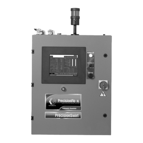
Graco PrecisionFlo XL User manual

Graco

Graco PrecisionFlo XL User manual

Graco ProControl 1KS Instruction Manual

Graco

Graco ProControl 1KS Instruction Manual

Graco Series B Operation manual

Graco

Graco Series B Operation manual

Popular Controllers manuals by other brands

Sunricher SR-ZV9003T3-RGBW-US Installation

Sunricher

Sunricher SR-ZV9003T3-RGBW-US Installation

Ksenia intro Installation and configuration manual

Ksenia

Ksenia intro Installation and configuration manual

Inovance CAN200 Series manual

Inovance

Inovance CAN200 Series manual

Gauzy LC6 FLEX Controller Installation and operation guide

Gauzy

Gauzy LC6 FLEX Controller Installation and operation guide

Viking SLP-1 Technical practice

Viking

Viking SLP-1 Technical practice

CKD KBX-30E-U Series instruction manual

CKD

CKD KBX-30E-U Series instruction manual

Sharp Energy Sun Flux User manual & installation guide

Sharp Energy

Sharp Energy Sun Flux User manual & installation guide

Yamaha RCX40 user manual

Yamaha

Yamaha RCX40 user manual

AB Quality PowerFlex 400 Frames D-H Service bulletin

AB Quality

AB Quality PowerFlex 400 Frames D-H Service bulletin

Yamaha MJC8 owner's manual

Yamaha

Yamaha MJC8 owner's manual

AL-KO ATC operating instructions

AL-KO

AL-KO ATC operating instructions

Savant SmartControl 2 Deployment guide

Savant

Savant SmartControl 2 Deployment guide

GameSir T3S user manual

GameSir

GameSir T3S user manual

Kostal inveor operating manual

Kostal

Kostal inveor operating manual

Emerson Yarway 20-55 Operating and safety instructions

Emerson

Emerson Yarway 20-55 Operating and safety instructions

CoCo ACM-LV24 Quick installation guide

CoCo

CoCo ACM-LV24 Quick installation guide

Brooks SLA5810/20 Installation and operation manual

Brooks

Brooks SLA5810/20 Installation and operation manual

SIGMA TEK SR 011 Technical manual

SIGMA TEK

SIGMA TEK SR 011 Technical manual

manuals.online logo
manuals.online logoBrands
  • About & Mission
  • Contact us
  • Privacy Policy
  • Terms and Conditions

Copyright 2025 Manuals.Online. All Rights Reserved.

Instructions
Pro Xpc™ Auto Controller 333266D
EN
For controlling the Graco Pro Xpc Auto Electrostatic Spray Guns. For professional use only.
Not approved for use in explosive atmospheres or hazardous locations.
Important Safety Instructions
Read all warnings and instructions in this manual and in your
Pro Xpc™ Auto Electrostatic Air Spray Gun manual.
Save these
instructions.
PROVEN QUALITY. LEADING TECHNOLOGY.
Contents
Related Manuals ................................................ 3
Models............................................................... 3
Approved System Components ........................... 3
arnings ........................................................... 4
Introduction........................................................ 6
Controller Features and Options.......................... 6
Installation Options ............................................. 6
Interlocks..................................................... 7
No Integration.............................................. 9
Basic Integration.......................................... 10
PLC Integration............................................ 11
Pre-Installation Steps.......................................... 12
Ventilate the Spray Booth.............................12
Install the Pro Xpc Auto Spray Gun ............... 12
Interlock aterborne Isolation
Enclosure....................................... 12
Mount the Controller ........................................... 13
Location ...................................................... 13
Mounting ..................................................... 13
Grounding ................................................... 14
Controller Connections........................................ 15
Overview..................................................... 15
Connections ................................................ 16
Discrete I/O........................................................ 18
Isolation ...................................................... 18
I/O Grounding.............................................. 18
REMOTE Input Operation............................. 18
REMOTE Output Operation.......................... 18
Signals........................................................ 19
Analog Inputs .............................................. 23
Analog Outputs............................................ 23
Digital Inputs................................................ 24
Digital Outputs............................................. 24
Timing Diagrams.......................................... 24
Controller Display and Features........................... 30
Screen Areas............................................... 30
Icons........................................................... 30
Input Keys and Switches .............................. 31
Additional Features ...................................... 31
Setup................................................................. 33
Setup Screen 0............................................ 35
Setup Screen 1............................................ 35
Setup Screen 2............................................ 36
Setup Screen 3............................................ 36
Setup Screen 4............................................ 37
Setup Screen 5............................................ 37
Setup Screen 6............................................ 37
Setup Screen 7............................................ 37
Setup Screen 8............................................ 38
Setup Screen 9............................................ 38
Setup Screen 10.......................................... 39
Setup Screen 11.......................................... 39
Operation........................................................... 40
System Start-up........................................... 40
Run Screen 1 ..............................................40
Run Screen 2 ..............................................41
Run Screen 3 ..............................................42
Arc Detection............................................... 43
Screen Map........................................................ 45
Error Code Troubleshooting ................................ 48
Repair................................................................ 51
Main Circuit Board or Keypad Membrane
Removal ........................................ 51
Power Board Removal ................................. 53
Software Update.......................................... 54
Parts.................................................................. 55
Dimensions........................................................ 56
Technical Data ................................................... 59
Graco Standard arranty.................................... 60
2333266D
Related Manuals
Related Manuals
Manual
No. Description
332992 Pro Xpc Auto Electrostatic Air Spray
Gun
Models
Controller Description Maximum Gun Voltage Output
24Y307 Pro Xpc Auto Controller, solventborne 100 kV
24Y308 Pro Xpc Auto Controller, waterborne 60 kV
Approved System Components
Specific controllers, guns, and gun power cables must be used together. Refer to the table below for
compatible models.
Controller Gun
Models Gun
Po er
Cables
Product Type Approvals
24Y307 LC1020
LC2020 Solventborne
24Y308 LC1028
LC2028
17H040
17H041
17H042
aterborne
333266D 3
Warnings
Warnings
The following warnings are for the setup, use, grounding, maintenance, and repair of this equipment. The
exclamation point symbol alerts you to a general warning and the hazard symbols refer to procedure-specific
risks. hen these symbols appear in the body of this manual or on warning labels, refer back to these
arnings. Product-specific hazard symbols and warnings not covered in this section may appear throughout
the body of this manual where applicable.
WARNING
FIRE AND EXPLOSION HAZARD
Flammable fumes, such as solvent and paint fumes, in work location can ignite or explode.
Paint or solvent flowing through the system can cause static sparking. To help prevent fire or
explosion:
• Electrostatic equipment must be used only by trained, qualified personnel who understand
the requirements of this manual.
• Ground all equipment, personnel, object being sprayed, and conductive objects in or close to
the spray location. Resistance must not exceed 1 megohm. See
Grounding
instructions.
• Do not use pail liners unless they are conductive and grounded.
•
Stop operation immediately
if static sparking occurs. Do not use equipment until you identify
and correct the problem.
• Check gun resistance and electrical grounding daily.
• Use and clean equipment only in a well ventilated location.
• Never spray or flush solvent at high pressure.
• Always turn the electrostatics off when flushing, cleaning, or servicing equipment.
• Eliminate all ignition sources; such as pilot lights, cigarettes, portable electric lamps, and
plastic drop cloths (potential static arc).
• Do not plug or unplug power cords or turn lights on or off when flammable fumes are present.
• Keep spray location free of debris, including solvent, rags, and gasoline.
• Keep a working fire extinguisher in the work location.
For solventborne systems only:
• Use cleaning solvents with highest possible flash point when flushing or cleaning equipment.
For aterborne systems only:
• Do not spray or clean with flammable materials. Use water-based materials only.
ELECTRIC SHOCK HAZARD
This equipment must be grounded. Improper grounding, setup, or usage of the system can
cause electric shock.
• Turn off and disconnect power at main switch before disconnecting any cables and before
servicing or installing equipment.
• Connect only to grounded power source.
• All electrical wiring must be done by a qualified electrician and comply with all local codes
and regulations.
4333266D
Warnings
WARNING
EQUIPMENT MISUSE HAZARD
Misuse can cause death or serious injury.
• Do not operate the unit when fatigued or under the influence of drugs or alcohol.
• Do not exceed the maximum working pressure or temperature rating of the lowest rated
system component. See
Technical Data
in all equipment manuals.
• Use fluids and solvents that are compatible with equipment wetted parts. See
Technical Data
in all equipment manuals. Read fluid and solvent manufacturer’s warnings. For complete
information about your material, request the Safety Data Sheet (SDS) from distributor or
retailer.
• Turn off all equipment and follow the
Pressure Relief Procedure
when equipment is not in use.
• Check equipment daily. Repair or replace worn or damaged parts immediately with genuine
manufacturer’s replacement parts only.
• Do not alter or modify equipment. Alterations or modifications may void agency approvals
and create safety hazards.
• Make sure all equipment is rated and approved for the environment in which you are using it.
• Use equipment only for its intended purpose. Call your distributor for information.
• Route hoses and cables away from traffic areas, sharp edges, moving parts, and hot surfaces.
• Do not kink or over bend hoses or use hoses to pull equipment.
• Keep children and animals away from work location.
• Comply with all applicable safety regulations.
TOXIC FLUID OR FUMES
Toxic fluids or fumes can cause serious injury or death if splashed in the eyes or on the skin,
inhaled, or swallowed.
• Read the Safety Data Sheet (SDS) to know the specific hazards of the fluids you are using.
• Store hazardous fluid in approved containers, and dispose of it according to applicable
guidelines.
PLASTIC PARTS CLEANING SOLVENT HAZARD
Many solvents can degrade plastic parts and cause them to fail, which could cause serious
injury or property damage.
• Use only compatible water-based solvents to clean plastic structural or pressure-containing
parts.
•See
Technical Data
in this and all other equipment instruction manuals. Read fluid and
solvent manufacturer’s Safety Data Sheet (SDS) and recommendations.
PERSONAL PROTECTIVE EQUIPMENT
ear appropriate protective equipment when in the work location to help prevent serious
injury, including eye injury, hearing loss, inhalation of toxic fumes, and burns. This protective
equipment includes but is not limited to:
• Protective eyewear, and hearing protection.
• Respirators, protective clothing, and gloves as recommended by the fluid and solvent
manufacturer.
333266D 5
Introduction
Introduction
The Pro Xpc Auto Controller is designed exclusively
for controlling a Graco electrostatic spray gun as part
of a paint coating system.
The controller sends power to the gun power supply,
which increases the voltage to the level set at the
controller. The fluid is charged by the spray gun
electrode. The charged fluid is attracted to the
nearest grounded object, wrapping around and
evenly coating all surfaces.
Controller Features and
Options
• The full voltage setting is 100 kV for solventborne
guns and 60 kV for waterborne guns.
• The controller can be flush mounted at the front
plate or wall mounted. See Mounting, page 13.
The Pro Xpc Auto Controller provides the ability to:
• Display and set the voltage and current.
• Create and store spray presets.
• Operate the spray gun remotely via discrete I/O.
The controller has three interlocks. These interlocks
must be satisfied before the system will operate.
Check and follow all National, State, and Local codes
regarding properly interlocking your spray system.
Also see Ventilate the Spray Booth, page 12.
Installation Options
Installation details vary widely depending on the
system requirements. This section shows three
typical installations. They are not actual system
designs. For assistance in designing a system to suit
your particular needs, contact your Graco distributor.
Installing and servicing this equipment requires
access to parts which may cause fire, explosion,
electric shock or other serious injury if work is not
performed properly.
• Do not install or service this equipment unless
you are trained and qualified.
• Be sure your installation complies with national,
state, and local codes for the installation of
electrical apparatus in a Class I, Division 1, or a
Group II, Zone 1 Hazardous Location.
• Comply with all applicable local, state, and
national fire, electrical, and other safety
regulations.
6333266D
Installation Options
Interlocks
Interlocks are required to ensure that the system
is safe to operate. The controller can use internal
or external signals to receive verification that the
conditions the interlocks are monitoring are in a state
that is safe for the system to operate.
Determine how the following interlocks will be used.
The following table shows how to use the Pro
Xpc Auto Controller for each interlock. The table
also explains how to bypass the interlock if the
requirement is being satisfied in another manner.
If other forms of interlock are implemented that
precludetheneedtousethecontrollerinterlocks,the
controller interlocks can be disabled.
Interlock Pin Description
System
Interlock Input power
cord, Pin 3
(wire 3)
If required, use Pin #3 on the Input Power Connection. See Step 2 in
Connections, page 16.
If not required, bypass the interlock by connecting wire 3 to line voltage on the
Input Power cord. The icon will be displayed.
24VDC
Interlock Discrete
I/O cable,
pin 19
If required, Pin #19 on the Discrete I/O Cable Connection is used to indicate the
condition of a 0VDC/24VDC signal being used as an interlock. This pin can be
used to connect to an external device, such as a ventilation interlock signal to
the controller. Input signal values are:
0 (0VDC or GND): Interlock not satisfied; electrostatics cannot be enabled
1 (24VDC): interlock satisfied
If not required, apply a constant 24VDC to Pin #19, or see
Disable Controller Interlocks, page 8 .
Symbol A9 on the display screen (see Screen Areas, page 30) will show that
this signal is satisfied.
SAFE
POSITION
Interlock
Discrete
I/O cable,
pin 18
If required, Pin #18 on the Discrete I/O Cable Connection requires 24VDC to be
applied for electrostatics to turn on. Apply only when the applicator is in SAFE
POSITION. See SAFE POSITION, page 26. If electrostatics are on, removing
24VDC from this pin will not turn off the electrostatics.
If not required, apply a constant 24VDC to Pin #18, or see
Disable Controller Interlocks, page 8 .
SymbolA10onthedisplayscreen(seeScreen Areas, page 30)willshowthat
this signal is satisfied.
333266D 7
Installation Options
Disable Controller Interlocks
If interlock requirements have been satisfied in
your system by means other than the Pro Xpc Auto
Controller, the controller interlocks can be disabled.
1. To disable the system interlock, connect wire 3
on the controller input power cord to line voltage.
The icon will be lit on the display screen.
2. Remove power from the controller.
3. Remove 4 screws and take off the access cover.
4. Locate the interlock switches on the main board.
hen the switches are in the ON position, the
interlocks are considered satisfied.
Switch 1 is the 24VDC Interlock (pin 19 on
the Discrete I/O cable). Switch 2 is the SAFE
POSITIONInterlock(Pin18ontheDiscreteI/O
cable).
Symbols in A9 and A10 (see
Screen Areas, page 30)onthedisplay
screen will show that these signals are satisfied.
ON
GOHO2
Switches shown in OFF position.
8333266D
Installation Options
No Integration
The defining characteristics of a No Integration
installation include:
• No integration of the Pro Xpc Auto Air Spray Gun
or Controller.
• Local operation using the Pro Xpc Auto Controller
interface.
• Interlocks managed independently of the spray
gun installation.
To reduce the risk of fire and explosion, the
controller (B) must be electrically interlocked with
the spray booth ventilation fans to prevent the gun
from operating without ventilation fans operating.
Non-Hazardous Location Hazardous Location
KEY:
A
Pro Xpc Auto Air Spray
Gun
B
Pro Xpc Auto Controller
C
Gun Power Cable
D
Fluid Supply
F
‡
Fluid Hose Ground
Bracket
G
‡
Fluid Bracket Ground
ire
H
‡
Fluid Supply Tube
(Graco-supplied) to gun
fluid inlet, maximum 8 ft
(2.4 m) length
†
Graco aterborne Fluid
Supply Hose, from L to
gun inlet (hose must be
a single, uninterrupted
length).
J
‡
Fluid Supply Hose
K
Pro Xpc Auto Controller
Ground ire
L
Fluid Regulator
M
†
Isolation Enclosure
X
Controller Power Cord
†
aterborne systems only
‡
Solventborne systems only
Typical Installation ith No Integration
333266D 9
Installation Options
Basic Integration
The Discrete I/O cable provides for 19 possible
discrete I/O signals. This example shows a basic
integration, using 6 of the I/O signals. The defining
characteristics of a Basic Integration installation
include:
• Integration of basic gun and controller functions.
• Integration of controller interlocks.
• Local operation of setup and error functions.
The signals used include:
•
Preset Select 1 (Pin #1) and Preset Select 2 (Pin
#2):
Select Preset 2 by applying 24V to Pin #1 and
Ground or no connection to Pin #2.
•
Remote Enable/Disable (Pin #4):
Enable remote
control by applying 24V to Pin #4.
•
Pin # 5:
Use a switched voltage source for Pin #5
to activate/trigger the electrostatics.
•
GND:
Used as ground reference for I/O signals.
•
Interlocks:
See Interlocks, page 7 , for information
on how to set up the required interlocks.
To reduce the risk of fire and explosion, the
controller (B) must be electrically interlocked with
the spray booth ventilation fans to prevent the gun
from operating without ventilation fans operating.
Non-Hazardous
Location
Hazardous Location KEY:
A
Pro Xpc Auto Air Spray Gun
B
Pro Xpc Auto Controller
C
Gun Power Cable
D
Fluid Supply
E
Integration Signals
E1: Discrete I/O Cable pin 1
E2: Discrete I/O Cable pin 4
E3: Discrete I/O Cable pin 5
E4: Discrete I/O Cable pin 18
E5: Discrete I/O Cable pin 19
GND: Discrete I/O Cable pins 8 12 17
F
‡
Fluid Hose Ground Bracket
G
‡
Fluid Bracket Ground Wire
H
‡
Fluid Supply Tube (Graco-supplied) to
gun fluid inlet maximum 8 ft (2.4 m) length
†
Graco Waterborne Fluid Supply Hose
from L to gun inlet (hose must be a single
uninterrupted length).
J
‡
Fluid Supply Hose
K
Pro Xpc Auto Controller Ground Wire
L
Fluid Regulator
M
Discrete I/O Cable
N
†
Isolation Enclosure
X
Controller Power Cord
Typical Installation ith Basic Integration
†
Waterborne systems only
‡
Solventborne systems only
10 333266D