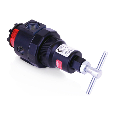
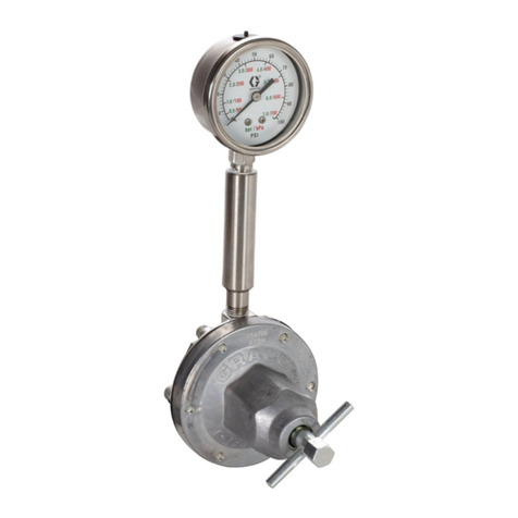
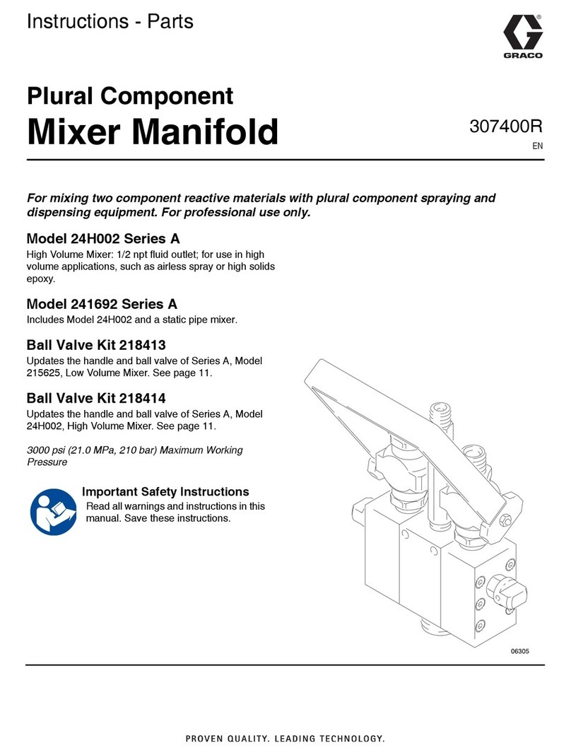
Graco C Series User manual
Other Graco Controllers manuals
Graco
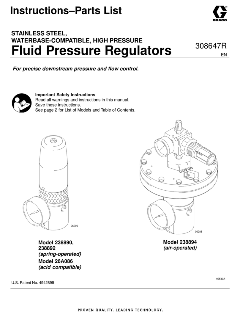
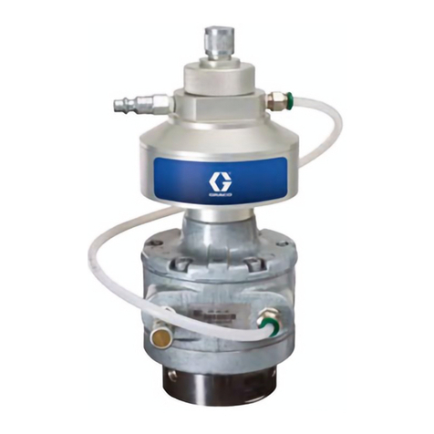
Graco 238889 Operation manual
Graco
Graco 24G621 Parts list manual

Graco
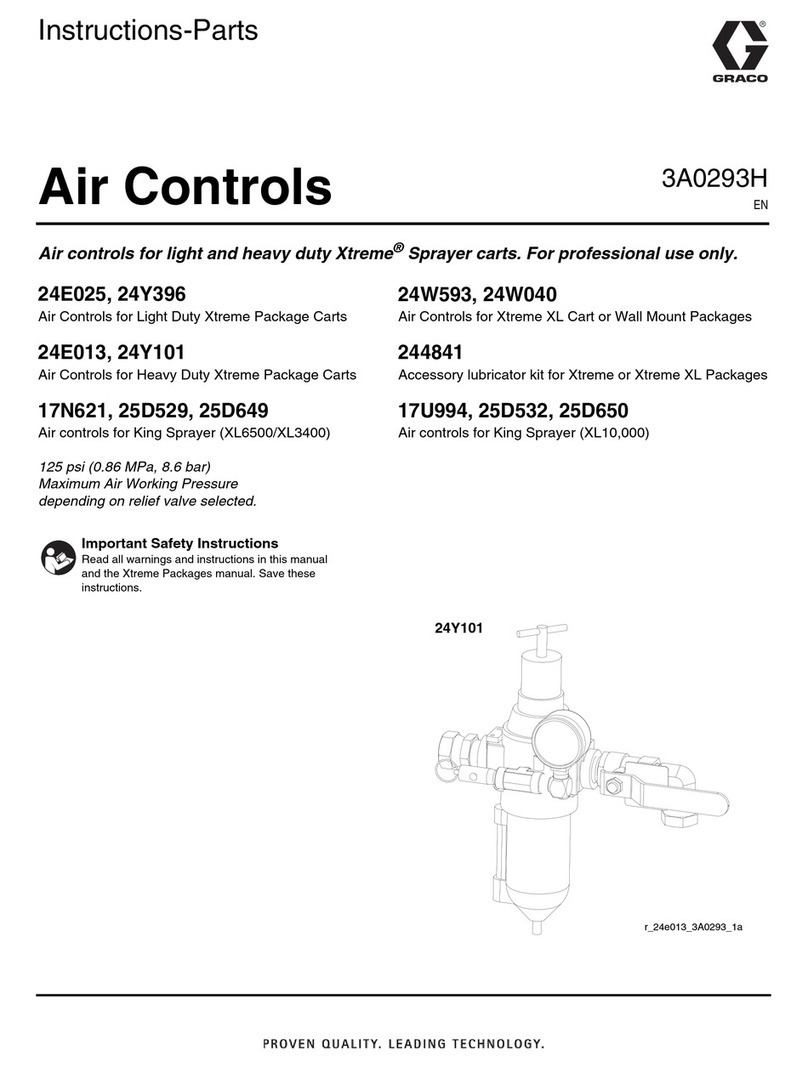
Graco 15J753 User manual
Graco
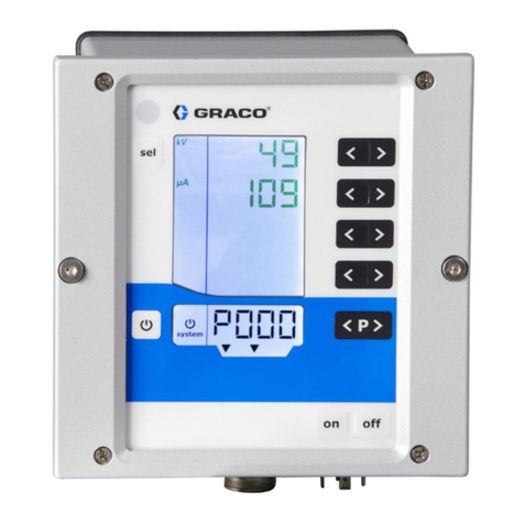
Graco 24E025 Operation manual
Graco
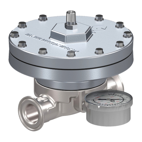
Graco Pro Xpc 24Y307 User manual
Graco
Graco 311595C Parts list manual
Graco
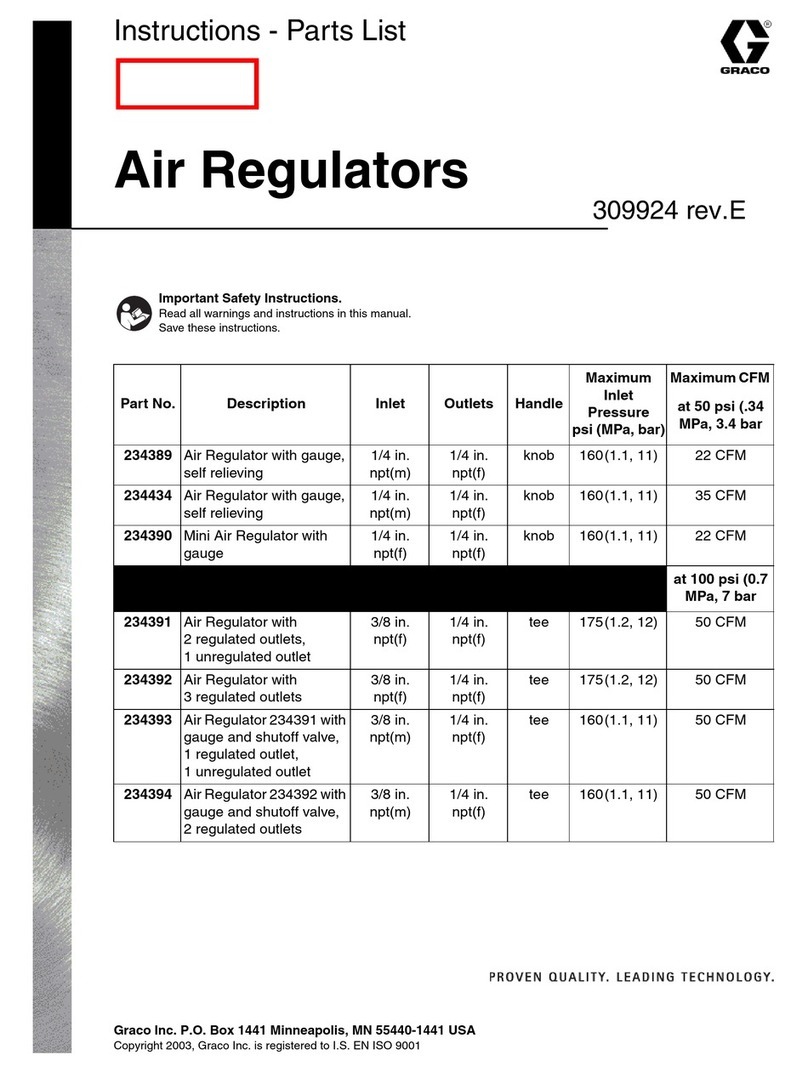
Graco 234389 Operation manual
Graco
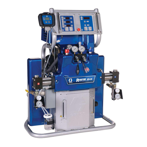
Graco IPH-25 Series Guide
Graco
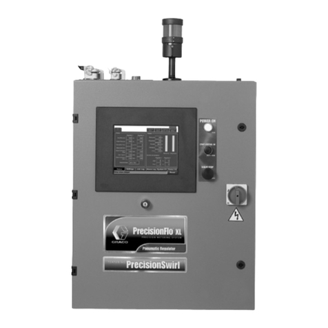
Graco PrecisionFlo XL User manual
Graco
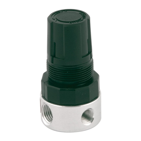
Graco 104815 Operation manual
Graco
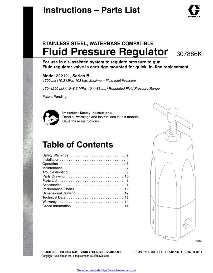
Graco Series B Operation manual
Graco
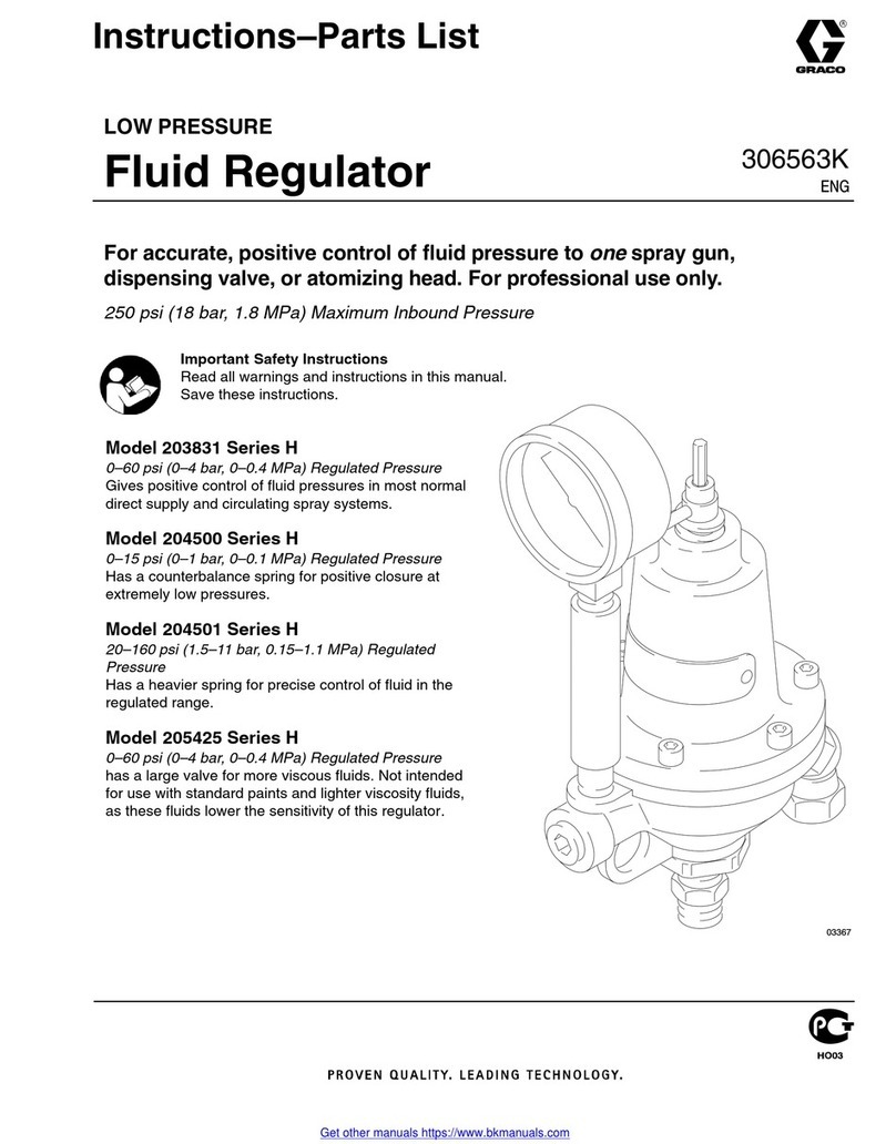
Graco H Series Operation manual
Graco
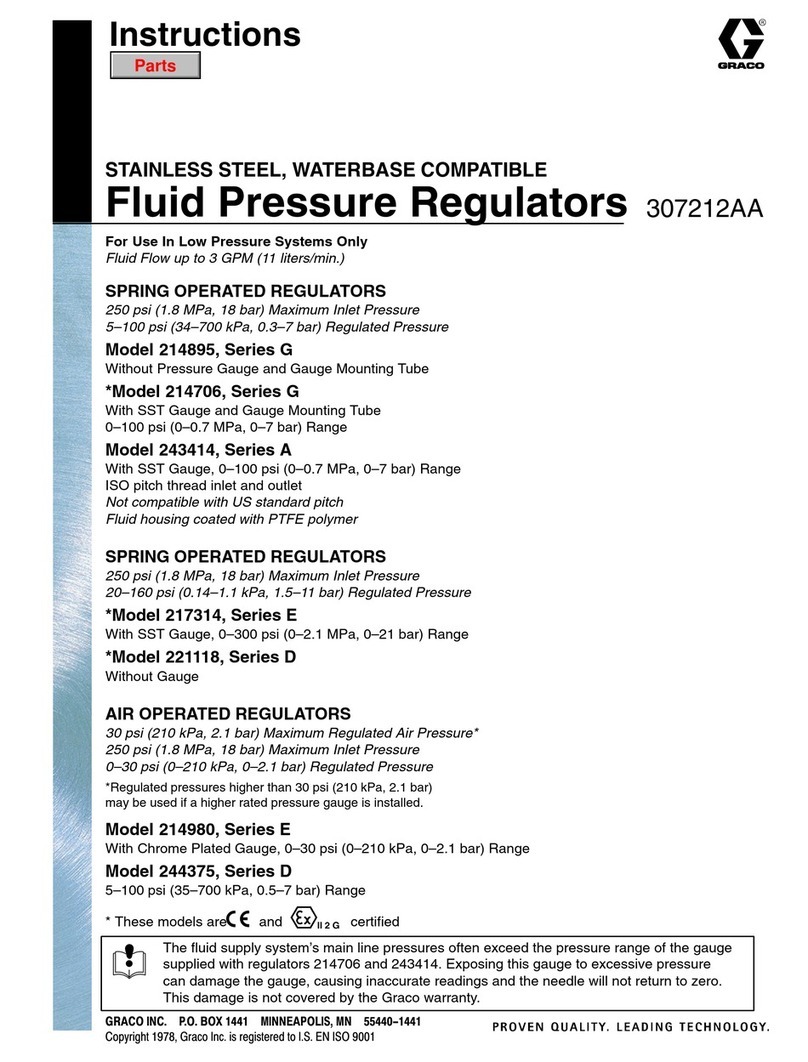
Graco 214706 User manual
Graco
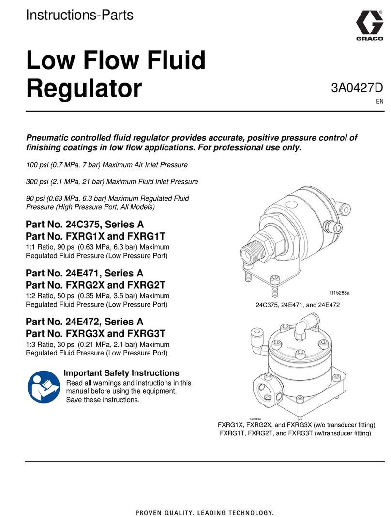
Graco Series A Parts list manual
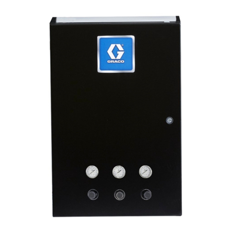
Graco
Graco ProBell 24Z221 Parts list manual

Graco
Graco G Series Operation manual

Graco
Graco Series A Parts list manual
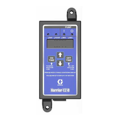
Graco
Graco Harrier EZ-Batch User manual
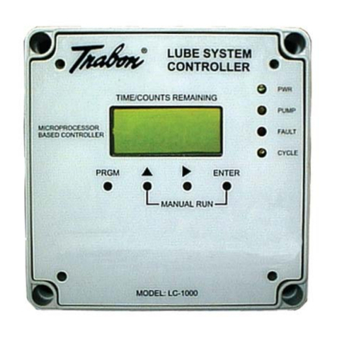
Graco
Graco Trabon LC-1000 User manual
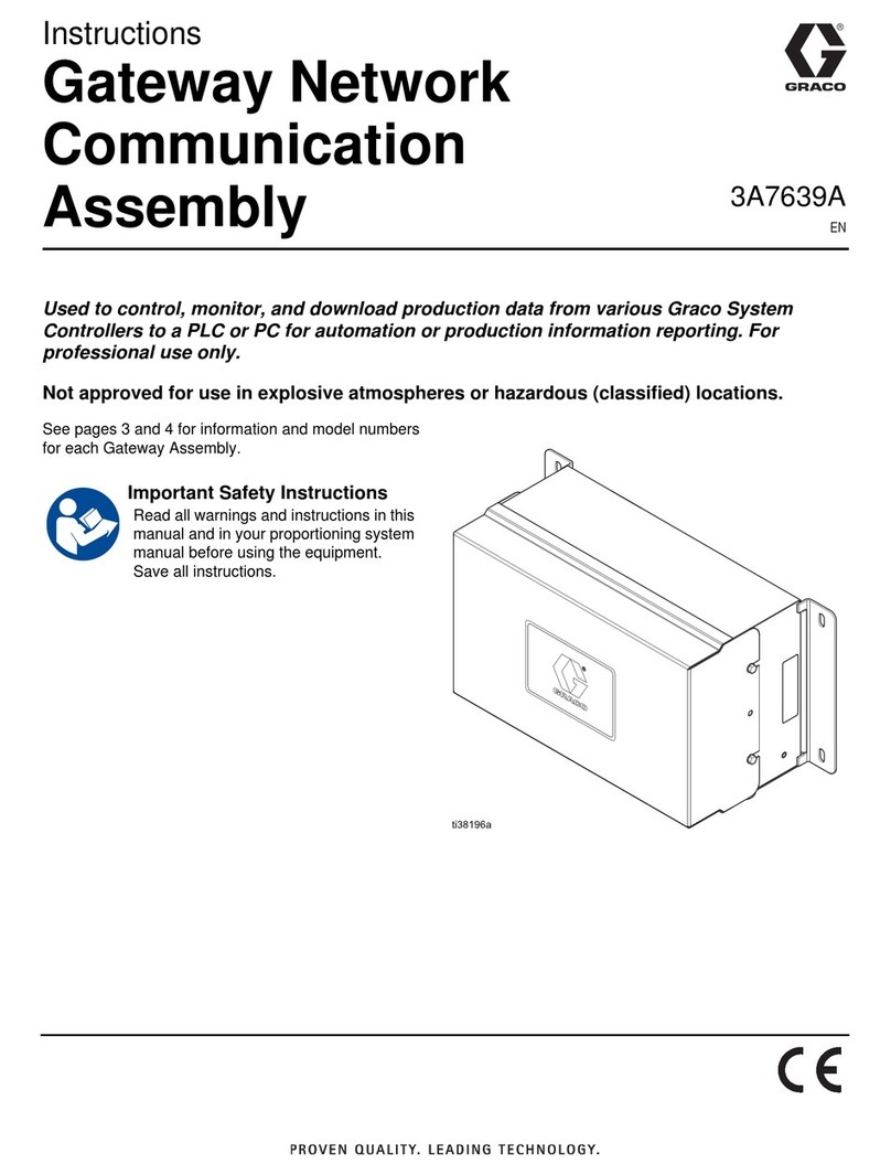
Graco
Graco 3A7639A User manual
Popular Controllers manuals by other brands

Digiplex
Digiplex DGP-848 Programming guide

YASKAWA
YASKAWA SGM series user manual

Sinope
Sinope Calypso RM3500ZB installation guide

Isimet
Isimet DLA Series Style 2 Installation, Operations, Start-up and Maintenance Instructions

LSIS
LSIS sv-ip5a user manual

Airflow
Airflow Uno hab Installation and operating instructions
