Graco Therm-O-Flow 200 Parts list manual

334130L
EN
Instructions-Parts
Therm-O-Flow®200
For applying hot melt sealant and adhesive materials from 200 Liter (55 Gallon) drums. For
professional use only.
Not approved for use in European explosive atmosphere locations.
Maximum Operating Temperature 400°F (204°C)
See page 6 for model information.
See Technical Specifications, page 111, for maximum
working pressures.
Important Safety Instructions
Read all warnings and instructions in this manual
and in related manuals. Save these instructions.
3143485

2334130L
Contents
Warnings . . . . . . . . . . . . . . . . . . . . . . . . . . . . . . . . . 3
Models . . . . . . . . . . . . . . . . . . . . . . . . . . . . . . . . . . . 6
Related Manuals . . . . . . . . . . . . . . . . . . . . . . . . . . . 7
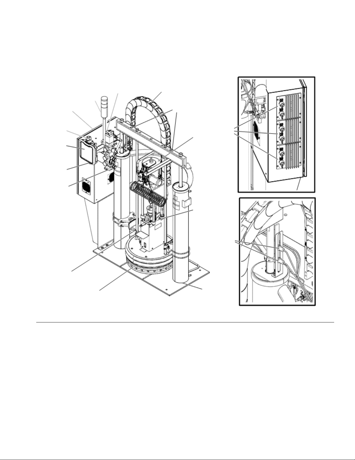
Component Identification . . . . . . . . . . . . . . . . . . . . 8
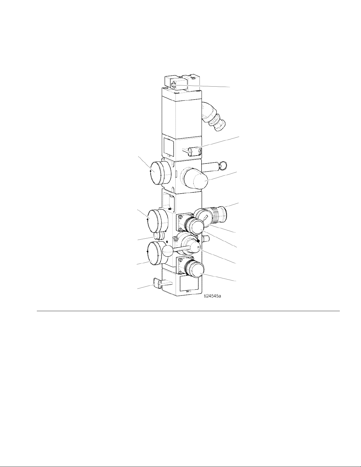
Integrated Air Controls . . . . . . . . . . . . . . . . . . . . 9
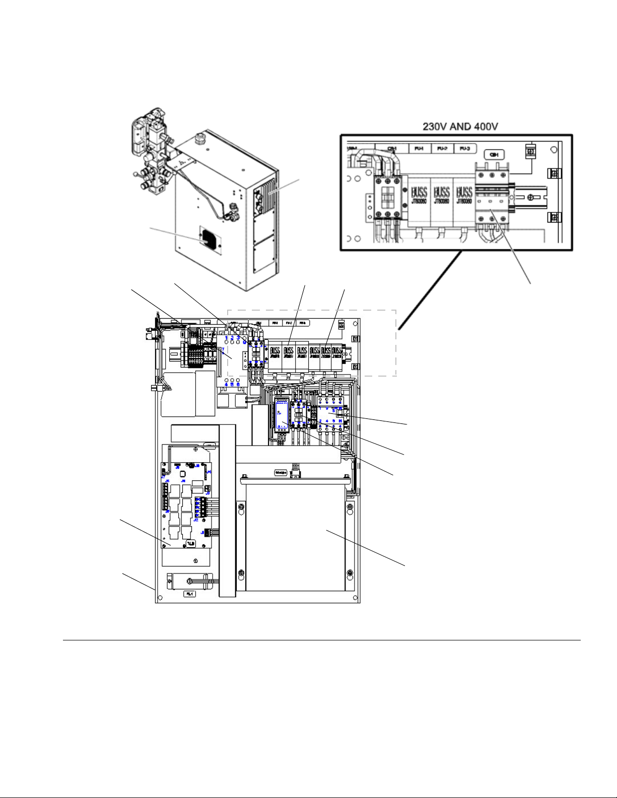
Electrical Control Enclosure . . . . . . . . . . . . . . . 10
Advanced Display Module (ADM) . . . . . . . . . . . 11
Screen Components . . . . . . . . . . . . . . . . . . . . . 13
Overview . . . . . . . . . . . . . . . . . . . . . . . . . . . . . . . . . 14
Air and Fluid Hoses . . . . . . . . . . . . . . . . . . . . . . 14
Heat Control Zone . . . . . . . . . . . . . . . . . . . . . . . 14
Setup . . . . . . . . . . . . . . . . . . . . . . . . . . . . . . . . . . . . 15
Unpack . . . . . . . . . . . . . . . . . . . . . . . . . . . . . . . 15
Location Requirements . . . . . . . . . . . . . . . . . . . 15
Install System . . . . . . . . . . . . . . . . . . . . . . . . . . 15
Install Hydraulic Power Supply . . . . . . . . . . . . . 15
Mechanical Setup . . . . . . . . . . . . . . . . . . . . . . . 16
Install Heated Hose . . . . . . . . . . . . . . . . . . . . . . 17
Connect Multiple Devices . . . . . . . . . . . . . . . . . 18
Connect Power . . . . . . . . . . . . . . . . . . . . . . . . . 19
Grounding . . . . . . . . . . . . . . . . . . . . . . . . . . . . . 20
Connect Secondary System . . . . . . . . . . . . . . . 20
Check Sensor Resistance . . . . . . . . . . . . . . . . . 21
Check Heater Resistance . . . . . . . . . . . . . . . . . 22
Select ADM Settings . . . . . . . . . . . . . . . . . . . . . 23
Connect PLC (Hard Wired Interface Version) . . 25
Operation . . . . . . . . . . . . . . . . . . . . . . . . . . . . . . . . 28
Purge System . . . . . . . . . . . . . . . . . . . . . . . . . . 28
Load Material . . . . . . . . . . . . . . . . . . . . . . . . . . 29
Heat Up System . . . . . . . . . . . . . . . . . . . . . . . . 30
Prime Pump . . . . . . . . . . . . . . . . . . . . . . . . . . . 31
Prime System . . . . . . . . . . . . . . . . . . . . . . . . . . 33
Setback Mode . . . . . . . . . . . . . . . . . . . . . . . . . . 33
Pressure Relief Procedure . . . . . . . . . . . . . . . . 34
Shutdown . . . . . . . . . . . . . . . . . . . . . . . . . . . . . 35
Schedule . . . . . . . . . . . . . . . . . . . . . . . . . . . . . . 35
Change Drums . . . . . . . . . . . . . . . . . . . . . . . . . 36
Troubleshooting . . . . . . . . . . . . . . . . . . . . . . . . . . 37
Light Tower (Optional) . . . . . . . . . . . . . . . . . . . 37
Error Codes . . . . . . . . . . . . . . . . . . . . . . . . . . . . 38
Ram Troubleshooting . . . . . . . . . . . . . . . . . . . . 44
Heated Pump Troubleshooting . . . . . . . . . . . . . 45
Air Motor Troubleshooting . . . . . . . . . . . . . . . . . 45
Repair . . . . . . . . . . . . . . . . . . . . . . . . . . . . . . . . . . . 46
Replace Wipers . . . . . . . . . . . . . . . . . . . . . . . . . 46
Replace Platen RTD . . . . . . . . . . . . . . . . . . . . . 46
Separate the Air Motor and Pump . . . . . . . . . . . 47
Remove Platen . . . . . . . . . . . . . . . . . . . . . . . . . 50
Replace Heater Band and Pump RTD . . . . . . . 50
Replace MZLP Fuse . . . . . . . . . . . . . . . . . . . . . 51
Replace MZLP . . . . . . . . . . . . . . . . . . . . . . . . . . 52
Replace MZLP Daughter Card . . . . . . . . . . . . . 53
Replace AWB . . . . . . . . . . . . . . . . . . . . . . . . . . 54
Replace Power Supply . . . . . . . . . . . . . . . . . . . 54
Replace Fan . . . . . . . . . . . . . . . . . . . . . . . . . . . 55
Replace Transformer . . . . . . . . . . . . . . . . . . . . . 56
Update Software . . . . . . . . . . . . . . . . . . . . . . . . 58
Electrical Schematics . . . . . . . . . . . . . . . . . . . . . . 59
Parts . . . . . . . . . . . . . . . . . . . . . . . . . . . . . . . . . . . . 65
Accessories and Kits . . . . . . . . . . . . . . . . . . . . . . . 89
Wiper Kits . . . . . . . . . . . . . . . . . . . . . . . . . . . . . 89
Applicators and Dispense Valves . . . . . . . . . . . 89
CGM Installation Kit, 25C994 . . . . . . . . . . . . . . 89
Flow Control and Manifolds . . . . . . . . . . . . . . . . 89
Accessory Extension Cables . . . . . . . . . . . . . . . 90
Light Tower Kit, 24W589 . . . . . . . . . . . . . . . . . . 90
Heated Hoses and Fittings . . . . . . . . . . . . . . . . 91
8 Channel Upgrade Kit, 24V755 . . . . . . . . . . . . 93
12 Channel Upgrade Kit, 24V756 . . . . . . . . . . . 95
Appendix A - ADM . . . . . . . . . . . . . . . . . . . . . . . . . 98
General Operation . . . . . . . . . . . . . . . . . . . . . . . 98
ADM Power . . . . . . . . . . . . . . . . . . . . . . . . . . . . 98
Screen Navigation . . . . . . . . . . . . . . . . . . . . . . . 98
Enable, Disable Heating System . . . . . . . . . . . . 98
Icons . . . . . . . . . . . . . . . . . . . . . . . . . . . . . . . . . 99
Operation Screens . . . . . . . . . . . . . . . . . . . . . . 100
Setup Screens . . . . . . . . . . . . . . . . . . . . . . . . . 102
Appendix B - USB Data . . . . . . . . . . . . . . . . . . . . 107
Download . . . . . . . . . . . . . . . . . . . . . . . . . . . . . 107
Access Files . . . . . . . . . . . . . . . . . . . . . . . . . . 107
Upload . . . . . . . . . . . . . . . . . . . . . . . . . . . . . . . 107
USB Logs . . . . . . . . . . . . . . . . . . . . . . . . . . . . 108
System Settings File . . . . . . . . . . . . . . . . . . . . 108
System Language File . . . . . . . . . . . . . . . . . . . 109
Create Custom Language Strings . . . . . . . . . . 109
Dimensions . . . . . . . . . . . . . . . . . . . . . . . . . . . . . . 110
Technical Specifications . . . . . . . . . . . . . . . . . . . 111
Graco Standard Warranty . . . . . . . . . . . . . . . . . . 112

Warnings
334130L 3
Warnings
The following warnings are for the setup, use, grounding, maintenance, and repair of this equipment. The exclama-
tion point symbol alerts you to a general warning and the hazard symbols refer to procedure-specific risks. When
these symbols appear in the body of this manual or on warning labels, refer back to these Warnings. Product-specific
hazard symbols and warnings not covered in this section may appear throughout the body of this manual where
applicable.
WARNING
BURN HAZARD
Equipment surfaces and fluid that is heated can become very hot during operation. To avoid
severe
burns:
• Do not touch hot fluid or equipment.
SPLATTER HAZARD
Hot or toxic fluid can cause serious injury if splashed in the eyes or on skin. During blow off of platen,
splatter may occur.
• Use minimum air pressure when removing platen from drum.
MOVING PARTS HAZARD
Moving parts can pinch, cut or amputate fingers and other body parts.
• Keep clear of moving parts.
• Do not operate equipment with protective guards or covers removed.
• Pressurized equipment can start without warning. Before checking, moving, or servicing equipment,
follow the Pressure Relief Procedure and disconnect all power sources.
ELECTRIC SHOCK HAZARD
This equipment must be grounded. Improper grounding, setup, or usage of the system can cause electric
shock.
• Turn off and disconnect power at main switch before disconnecting any cables and before servicing or
installing equipment.
• Connect only to grounded power source.
• All electrical wiring must be done by a qualified electrician and comply with all local codes and regu-
lations.
TOXIC FLUID OR FUMES HAZARD
Toxic fluids or fumes can cause serious injury or death if splashed in the eyes or on skin, inhaled, or
swallowed.
• Read MSDSs to know the specific hazards of the fluids you are using.
• Store hazardous fluid in approved containers, and dispose of it according to applicable
guidelines.

Warnings
4334130L
THERMAL EXPANSION HAZARD
Fluids subjected to heat in confined spaces, including hoses, can create a rapid rise in pressure
due to
the thermal expansion. Over-pressurization can result in equipment rupture and serious
injury.
• Open a valve to relieve the fluid expansion during heating.
• Replace hoses proactively at regular intervals based on your operating conditions.
SKIN INJECTION HAZARD
High-pressure fluid from dispensing device, hose leaks, or ruptured components will pierce
skin. This
may look like just a cut, but it is a serious injury that can result in amputation. Get
immediate surgical
treatment.
• Engage trigger lock when not dispensing.
• Do not point dispensing device at anyone or at any part of the body.
• Do not put your hand over the fluid outlet.
• Do not stop or deflect leaks with your hand, body, glove, or rag.
• Follow the Pressure Relief Procedure when you stop dispensing and before cleaning, checking, or
servicing equipment.
• Tighten all fluid connections before operating the equipment.
• Check hoses and couplings daily. Replace worn or damaged parts immediately.
FIRE AND EXPLOSION HAZARD
Flammable fumes, such as solvent and paint fumes, in work area can ignite or explode. To help
prevent
fire and explosion:
• Use equipment only in well ventilated area.
• Eliminate all ignition sources; such as pilot lights, cigarettes, portable electric lamps, and
plastic drop
cloths (potential static arc).
• Keep work area free of debris, including solvent, rags and gasoline.
• Do not plug or unplug power cords, or turn power or light switches on or off when flammable
fumes are
present.
• Ground all equipment in the work area. See Grounding instructions.
• Use only grounded hoses.
• Hold gun firmly to side of grounded pail when triggering into pail. Do not use pail liners unless
they are
antistatic or conductive.
• Stop operation immediately if static sparking occurs or you feel a shock. Do not use
equipment until
you identify and correct the problem.
• Keep a working fire extinguisher in the work area.
WARNING

Warnings
334130L 5
EQUIPMENT MISUSE HAZARD
Misuse can cause death or serious injury.
• Do not operate the unit when fatigued or under the influence of drugs or alcohol.
• Do not exceed the maximum working pressure or temperature rating of the lowest rated
system com-
ponent. See Technical Data in all equipment manuals.
• Use fluids and solvents that are compatible with equipment wetted parts. See Technical Data in all
equipment manuals. Read fluid and solvent manufacturer’s warnings. For complete
information about
your material, request MSDS from distributor or retailer.
• Do not leave the work area while equipment is energized or under pressure.
• Turn off all equipment and follow the Pressure Relief Procedure when equipment is not in use.
• Check equipment daily. Repair or replace worn or damaged parts immediately with genuine
manufac-
turer’s replacement parts only.
• Do not alter or modify equipment. Alterations or modifications may void agency approvals
and create
safety hazards.
• Make sure all equipment is rated and approved for the environment in which you are using it.
• Use equipment only for its intended purpose. Call your distributor for information.
• Route hoses and cables away from traffic areas, sharp edges, moving parts, and hot surfaces.
• Do not kink or over bend hoses or use hoses to pull equipment.
• Keep children and animals away from work area.
• Comply with all applicable safety regulations.
PERSONAL PROTECTIVE EQUIPMENT
Wear appropriate protective equipment when in the work area to help prevent serious injury,
including
eye injury, hearing loss, inhalation of toxic fumes, and burns. This protective
equipment includes but is
not limited to:
• Protective eyewear, and hearing protection.
• Respirators, protective clothing, and gloves as recommended by the fluid and solvent
manufacturer.
WARNING

Models
6334130L
Models
The model number stamped on your systems defines the equipment in the following categories.
See Technical Specifications, page 111, for maximum working pressure.
SER A B C D E F G H
Series Frame Size Air
Air/Electric
Zone
Config
Pump
Ratio
Platen
Style
Platen
Seal
Ram Drum
Clamp
Code A Frame Size
200 55 Gallon (200 Liter)
Code B Air/Electric
A Air control only
E Air and Electric
Code C Zones, Volts, Type
11P 4 Zones, 230 V, Primary
11S 4 Zones, 230 V, Secondary
12P 4 Zones, 400 V/N, Primary
12S 4 Zones, 400 V/N, Secondary
13P 4 Zones, 400 V, Primary
13S 4 Zones, 400 V, Secondary
14P 4 Zones, 480 V, Primary
14S 4 Zones, 480 V, Secondary
15P 4 Zones, 600 V, Primary
15S 4 Zones, 600 V, Secondary
21P 8 Zones, 230 V, Primary
21S 8 Zones, 230 V, Secondary
22P 8 Zones, 400 V/N, Primary
22S 8 Zones, 400 V/N, Secondary
23P 8 Zones, 400 V, Primary
23S 8 Zones, 400 V, Secondary
24P 8 Zones, 480 V, Primary
24S 8 Zones, 480 V, Secondary
25P 8 Zones, 600 V, Primary
25S 8 Zones, 600 V, Secondary
31P 12 Zones, 230 V, Primary
31S 12 Zones, 230 V, Secondary
32P 12 Zones, 400 V/N, Primary
32S 12 Zones, 400 V/N, Secondary
33P 12 Zones, 400 V, Primary
33S 12 Zones, 400 V, Secondary
34P 12 Zones, 480 V, Primary
34S 12 Zones, 480 V, Secondary
35P 12 Zones, 600 V, Primary
35S 12 Zones, 600 V, Secondary
NNN None
Code D Pump Ratio
1 23:1 CF (carbon filled PTFE)
2 36:1
3 70:1
4 23:1 (glass filled PTFE)
5 36:1
6 70:1
Code E Platen Style
S Smooth Bottom (No Fin)
F Standard Finned Bottom
M Mega-Flo
Code F Platen Seal
1 2 Black EPDM/EPDM, SS wire braid 400°F
(204°C) hose wipers with spring retention
2 1 lower black EPDM/Chlorobutyl, SS wire
braid 400°F (204°C) hose wiper and 1
upper Green Silicone, fiberglass braid
400°F (204°C), hose wiper
3 2 White Silicone 250°F (121°C) T-Wipers
4 1 lower black EPDM/Chlorobutyl, SS wire
braid 375°F (190°C) hose wiper and 1
upper White Silicone 375°F (190°C),
T-wiper
5 2 Orange silicone o-ring 400°F (204°C)
Code G Ram
P Pneumatic
H Hydraulic
Code H Drum Clamps
NNone
1 Saddle Clamp
2 Fiber Clam Shell
3 Heavy Drum Band

Related Manuals
334130L 7
Related Manuals
Manual Description
334129 Therm-O-Flow 20, Instructions-Parts
3A5186 Communications Gateway Module
Therm-O-FLow
Air Motor Manuals
311238 NXT®Air Motor, Instructions-Parts
3A1211 Saniforce®Air Motor, Instructions-Parts
Displacement Pump Manual
334127 Check-Mate®800 Pump, Repair-Parts
334128 Check-Mate®800 Throat Seal Repair Kit,
Repair-Parts
Ram Manual
334198 Therm-O-Flow 200 Pneumatic and
Hydraulic Ram, Instructions-Parts
Accessory and Kit Manuals
3A4241 Heated Hose, Instructions-Parts
309160 Heated Hose, Instructions-Parts
309196 Wiper Kits, Repair-Parts
310538 Air-Operated Dispense Valves,
Instruc-
tions-Parts
311209 Top Feed and Bottom Feed Hot Melt
Dis-
pense Guns, Instructions-Parts
334201 Air Controls, Repair Kit

Component Identification
8334130L
Component Identification
Key:
A Lift Strap Positions
B Multi-Zone Low Power Temperature Control Module
(MZLP)
C Light Tower
D Cable Track
ERam
FHeatedPump
G Heated Platen
H Integrated Air Controls (3/4 in npt inlet)
J Electrical Control Panel
K Main Power Switch
LADM
M Air Motor Solenoid
N Electrical Power Input
PAirMotor
R Ram Plate Bleed Stick
S Drum Blow Off Valve (behind ram plate bleed stick)
T Drum Low and Empty Sensors
FIG. 1: TOF 200 Pneumatic
C
MD
A
PB
T
J
N
L
K
H
R, S
GE
ti24544a

Component Identification
334130L 9
Integrated Air Controls
Key:
CA Main Air Slider Valve
Turns air on and off to the entire system.
When closed,
the valve relieves pressure
downstream.
CB Ram Down Air Regulator
Controls the ram down pressure.
CC Ram Director Valve
Controls the ram direction.
CD Ram Up Air Regulator
Controls the ram up pressure.
CE Ram Down Air Gauge
Displays the ram down pressure.
CF Ram Up Air Gauge
Displays the ram up pressure.
CG Blowoff Button
Turns air on and off to push the platen out of an empty
drum.
CH Blowoff Pressure Gauge
Displays the blowoff pressure.
CJ Blowoff Air Regulator
Controls platen blowoff pressure.
CK Air Motor Air Regulator
Controls the air pressure to the motor.
CL Air Motor Pressure Gauge
Displays the air pressure to the motor.
CM Air Motor Slider Valve
Turns air on and off to the air motor. When
closed, the
valve relieves air trapped
between it and the motor. Push
the valve
in to shutoff air.
CN Air Motor Solenoid Valve
Turns air on and off to the air motor when
system stopped
on the ADM. When closed,
the valve relieves air trapped
between it and
the motor.
FIG. 2: Integrated Air Controls
CN
CM
CK
CJ
CH
CD
CC
CB
CA
CE
CG
CF
CL

Component Identification
10 334130L
Electrical Control Enclosure
Key:
DA Multi-Zone Low Power Temperature Control Module
(MZLP)
DB Ventilation Grill
DC Electrical Control Panel
DD Automatic Wiring Board (AWB)
DE Power Supply (24V)
DF Residual Current Device (GFI), 63A
DG Platen SSR (65A)
DH Platen Contractor
DJ Platen Fuse
DK Transformer Circuit Breaker
DL Transformer Fuse
DM Transformer
DN System Contactor
FIG. 3: Electrical Enclosure
Back Panel With Transformer
DL
DJ
DH
DG
DF
DN
DE
DM
DC
DD
DB
DA
DK

Component Identification
334130L 11
Advanced Display Module
(ADM)
The ADM display shows graphical and text
information
related to setup and spray operations. For detail on the
display and individual screens, see Appendix A - ADM,
page 98.
Use the USB port on the ADM to download or upload
da-
ta. For more information about the USB data, see
Ap-
pendix B - USB Data, page 107.
NOTICE
To prevent damage to the softkey buttons, do not
press buttons with sharp objects such as pens, plastic
cards, or fingernails.
FIG. 4: Front View
BB
BC
BD
BE
BF
BA
BH
BG
Key Function
BA Heating system and pump enable/disable
BB System status indicator (LED)
BC Stop all system processes
BD Defined by icon next to softkey
BE Abort current operation
BF Accept change, acknowledge error, select
item, toggle selected item
BG Toggle between Operation and Setup
screens
BH Navigate within a screen or to a new screen

Component Identification
12 334130L
Table 1 ADM LED Status Descriptions
FIG. 5: Back View
BK
BL
BM
BN
BP
BR
BK Part Number and Identification Label
BL USB Interface
BM CAN Cable Connection (Power Supply and
Communication)
BN Module Status LEDs
BP Light Tower (Optional)
BR Software Token Access Panel
LED Conditions Description
System Status Green Solid Run Mode, System On
Green Flashing Setup Mode, System On
Yellow Solid Run Mode, System Off
USB Status (BL) Green Flashing Data recording in progress
Yellow Solid Downloading information to USB
Green and Yellow Flashing ADM is busy, USB cannot transfer
information when in this mode
ADM Status (BN) Green Solid Power applied to module
Yellow Solid Active Communication
Red Steady Flashing Software upload from token in prog-
ress
Red Random Flashing or Solid Module error exists

Component Identification
334130L 13
Screen Components
1. Screen Order
2. Current date and time
3. Operating Mode
4. Faults, Status
5. MZLP Plug Identifier
6. Zone Setpoint Temperature
7. Zone Actual Temperature
Operating Mode Description Component Status
System Off The system does not have power. • No system status indicator LED on the
ADM
• No heat
• Pump is off
Inactive The heating system and pumps are dis-
abled.
• Yellow system indicator LED on the ADM
• No heat
• Pump is off
Warm Up The system is heating the material to the
setpoint temperature.
• Flashing green system status indicator
LED on the ADM
• Heat is increasing to setpoint temperature
• Pump is off
Heat Soak Heat zones are all at temperature. Material
is soaking for a user specified amount of
time.
• Flashing green system status indicator
LED on the ADM
• Heat is at setpoint
• Material is absorbing more heat
• Pump is off
• Heat soak counter counts down on the
Home screen.
Ready All enabled zones are at setpoint tempera-
ture. The air motor does not have power.
• Flashing green system status indicator
LED on the ADM
• Heat is at setpoint
• Pump is off
Active The system is ready to dispense. • Solid green system status indicator LED
on the ADM
• Heat is at setpoint temperature
• Pump is on

Overview
14 334130L
Overview
A heated platen melts the sealant or adhesive and
di-
rects the molten material to the pump inlet. The
material
then travels through a heated pump and
heated fluid
moves to the application tool.
Air and Fluid Hoses
The Therm-O-Flow requires Graco single-circuit
mate-
rial hoses rated at a maximum of 1250 watts.
Make sure
all air and fluid hoses are properly sized
for the system.
Heat Control Zone
The Therm-O-Flow has 4, 8, or 12 heat zones. Zones
for the heated drum platen and the heated pump are not
included in the zone count. Zones 1 and 2,
3 and 4, 5
and 6, 7 and 8, 9 and 10, and 11 and
12 are each avail-
able through 12-pin connectors. The heated hoses have
a 16-pin connector at the
inlet, and an 8-pin connector
at the outlet. All heated
valves, manifolds, and heaters
are equipped with an
8-pin mating connector.
FIG. 6: Heat Control Zone Selection

Setup
334130L 15
Setup
1. Unpack the ram
2. Locate and Install the ram
3. Mechanical Setup
4. Connect hoses to electrical control panel
5. Connect electrical control panel to power source
6. Ground system
7. Select ADM settings
Unpack
1. Inspect the shipping box carefully for damage. Con-
tact the carrier promptly if there is damage.
2. Open the box and inspect the contents carefully.
There should not be any loose or damaged parts in
the box.
3. Compare the packing slip against all items in the
box. Repost any shortages or other inspection prob-
lems immediately.
4. Remove the unit from the skid and place it in the
desired location. See Location Requirements.
Location Requirements
1. Make sure there is sufficient overhead clearance for
the pump and ram when the ram is in the fully raised
position (approximately 110 in. (280 cm)).
2. If you are installing a vent hood, make sure there is
sufficient horizontal clearance for it. Locate the ram
near a connection to the factory ventilation system.
3. Make sure the air regulators for the pump and ram
are fully accessible, with room to stand directly in
front of the pneumatic control panel and the electri-
cal control panel.
4. When locating the system, do not install closer than
36 in. (914 mm) to vertical surfaces.
5. Make sure there is easy access to an appropriate
electrical power source. The National Electrical
Code requires 3 ft (0.9 m) of open space in front of
the electrical panel. Comply with all local codes and
regulations.
6. For hydraulic rams, locate the hydraulic power sup-
ply in an area that has:
• easy access for servicing and adjusting the
hydraulic pressure on the supply unit
• sufficient clearance for the hydraulic lines that
attach to the pump
• easy access to read the hydraulic fluid level
gauge
Install System
Refer to Dimensions, page 110 for mounting and
clear-
ance dimensions.
Follow all Location Requirements, page 15, when
selecting a location for the ram.
1. Apply 50 psi download pressure to ram.
2. Wrap the bar with the lifting sling.
3. Lift the system off the pallet using a crane or a
fork-
lift and place in desired location.
4. Level the base of the ram, using metal shims.
5. Bolt the ram to the floor, using anchors that are
long
enough to prevent the unit from tipping.
Install Hydraulic Power Supply
See the Ram manual for installation and dimensions.

Setup
16 334130L
Mechanical Setup
1. Fill displacement pump wet cup 2/3 full with Graco
Throat Seal Liquid (TSL™) for Butyl and PSA mate-
rials.
NOTE: Use IsoGuard Select®(IGS) (part no. 24F516)
for PUR or reactive Polyurethane material. IGS is
designed to dissolve and suspend the Polyurethane
materials. IGS will solidify after a period of time and
should be replaced once the solidified lube does not
return to liquid form after heating.
2. Turn all air regulators to their full counterclockwise
position. See Integrated Air Controls, page 9.
3. Connect a 1/2 in. (13 mm) air line from an air source
to the system air inlet (H), capable of delivering a
minimum of 25-50 cfm at 100 psi (0.7 MPa, 7.0 bar).
Do not use quick disconnects.
4. Ensure drum low and empty sensors (C) are
mounted as shown.
NOTE: The Drum Low and Empty Sensors are
used to
indicate that a drum is empty.
The kit contains a sensor
mounting
bracket (A), activator (B), sensors (C1,
C2),
and a cable for connecting the panel
inside the electrical
enclosure.
5. Increase the distance between the low (C1) and
empty (C2) sensors to increase the heat up time for
the tandem secondary system. Lower the drum
empty sensor (C2) to force the heated platen lower
into the drum. If empty sensor is set too low, the
pump could cavitate and cause an alarm.
FIG. 7: Wetcup
FIG. 8: Air Connection
H
B
A
C1
C2

Setup
334130L 17
Install Heated Hose
To connect a hose to a fluid control device or heated
manifold.
1. Install fitting and heated hose onto pump outlet with
the large electrical connector side toward the sys-
tem. Use 2 wrenches to tighten hose. Torque to 45
ft-lbs (61 N•m).
NOTE: See Accessories and Kits, page 89, for avail-
able fittings and heated hoses.
2. Wrap exposed fittings on the pump outlet with
Nomex insulation and secure insulation using fiber-
glass tape.
3. Connect large heated hose connector to MZLP.
4. Repeat for any remaining channels.
5. For proper operation, cables must be plugged into
zones 1–2 and 3–4 at all times.
6. Install cap on any unused MZLP electrical connec-
tors.
7. Connect the small 8 pin connector from the heated
hose to the fluid control device or heated manifold.
NOTE: The heated manifold (part no. 243697) shown.
See Accessories and Kits, page 89, for available man-
ifolds and fluid control devices.
8. Use 2 wrenches to tighten hose. Torque to 45 ft-lbs
(61 N•m).
9. To connect multiple devices, see Connect Multiple
Devices, page 18.
FIG. 9
FIG. 10: Heated Manifold 243697

Setup
18 334130L
Connect Multiple Devices
If your application requires multiple fluid control
devices:
• Connect heated hose electrical connections to the
electrical enclosure. Remove from shipping box to
connect heated hoses to the electrical enclosure.
For additional cables, heated hose, and fluid control
devices, see Accessories and Kits, page 89.
• Connect fluid control devices to a heated hose or
the electrical enclosure. Use accessories if neces-
sary.
• Setup all heat zones on Heat-A and Heat-B
screens.
Example: Heated zones used to connect a primary and
secondary system to a manifold and two guns. A-#
zones are on the Heat-A screen and B-# zones are on
the Heat-B screen.
FIG. 11

Setup
334130L 19
Connect Power
The electrical control panel comes already attached and
wired to the ram, however before the supply unit
becomes functional you must connect the electrical con-
trol panel to a power source.
NOTE: Required voltage and amperage is noted on the
control panel label. Before running power to the unit,
make sure the plant electrical service meets the
machine’s electrical requirements. Branch circuit protec-
tion shall be provided by the end user.
Use copper conductors rated 600 volts minimum and
167°F (75°C) minimum only. Torque to 55 in-lb (6.2
N•m).
Table 2 Electrical Requirements
EF Standard Finned Bottom
EM Mega-Flo
ES Smooth Bottom
1. Locate the opening in the control panel’s top hous-
ing for the conduit that will enclose the wire from the
facility’s power source. The hole will accept a cord
diameter range of 0.7–1.2 in (17–30 mm).
2. Thread the wire from the power source into the con-
trol panel housing, and then connect the power
source wires to the appropriate terminals on the
DISCONNECT switch.
3. Connect the ground wire to the ground lug. Have a
qualified electrician check the resistance between
each Therm-O-Flow system ground and the true
earth ground. The resistance must be less than 0.1
ohms. If the resistance is greater than 0.1 ohms, a
different ground site may be required. Do not oper-
ate the system until the problem is corrected.
NOTE: Use a meter that is capable of measuring resis-
tance at this level.
All electrical wiring must be done by a qualified elec-
trician and comply with all local codes and regula-
tions.
Electrical
Panel
Voltage Hz Phase Platen
Full
Load
Amps AWG
230 V 50/60 3 EF, ES 90 3 AWG
EM 100 3 AWG
400 V/N 50/60 3 EF, ES 45 8 AWG
EM 50 8 AWG
400 V 50/60 3 EF, ES 45 8 AWG
EM 50 8 AWG
480 V 50/60 3 EF, ES 45 8 AWG
EM 50 8 AWG
600 V 50/60 3 EF, ES 50 8 AWG
3EM508AWG
FIG. 12
To reduce the risk of fire, explosion, or electric shock,
the resistance between the supply unit components
and true earth ground must be less than 0.25 ohms.

Setup
20 334130L
Grounding
Ground the unit as instructed here and in the compo-
nent manuals.
System: ground through ground lug in electrical enclo-
sure. See Connect Power, page 19.
Air and Fluid Hoses: use only electrically conductive
hoses.
Air compressor: follow manufacturer’s recommenda-
tions.
Spray gun / Dispense valve: ground through connec-
tion to a properly grounded fluid hose and pump.
Material drums: follow local code. Use only metal
drums placed on a grounded surface. Do not place the
drum on a nonconductive surface, such as paper or
cardboard, which interrupts the grounding continuity
To maintain grounding continuity when flushing or
relieving pressure: follow instructions in your separate
gun manual for instructions on how to safely ground
your gun while flushing.
Connect Secondary System
A secondary system is a Therm-O-Flow supply system
that connects to the primary Therm-O-Flow system, with
the ADM. See Models, page 6 for secondary system
model numbers.
1. Connect adapter cable (AC) and communication
cable (SC) to the secondary electrical enclosure
and rout to splitter (SS) installed on the primary sys-
tem.
2. To enable a secondary system, select “Enable Tan-
dem System” on the System 1 screen. See Select
ADM Settings, page 23.
The equipment must be grounded to reduce the risk
of static sparking and electric shock. Electric or static
sparking can cause fumes to ignite or explode.
Improper grounding can cause electric shock.
Grounding provides and escape path for the electric
current.
FIG. 13
AC
SC
SS
Other manuals for Therm-O-Flow 200
6
Table of contents
Other Graco Melting Machine manuals