manuals.online logo
Brands
  1. Home
  2. •
  3. Brands
  4. •
  5. Graco
  6. •
  7. Paint Sprayer
  8. •
  9. Graco 244113 User manual

Graco 244113 User manual

This manual suits for next models

3

Other Graco Paint Sprayer manuals

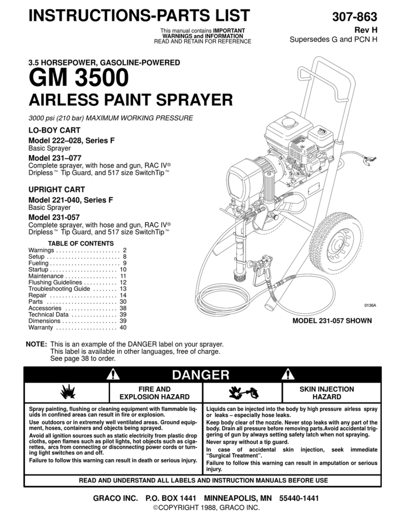
Graco ti13498a Operating instructions

Graco

Graco ti13498a Operating instructions

Graco XM User manual

Graco

Graco XM User manual

Graco 16F887 User manual

Graco

Graco 16F887 User manual

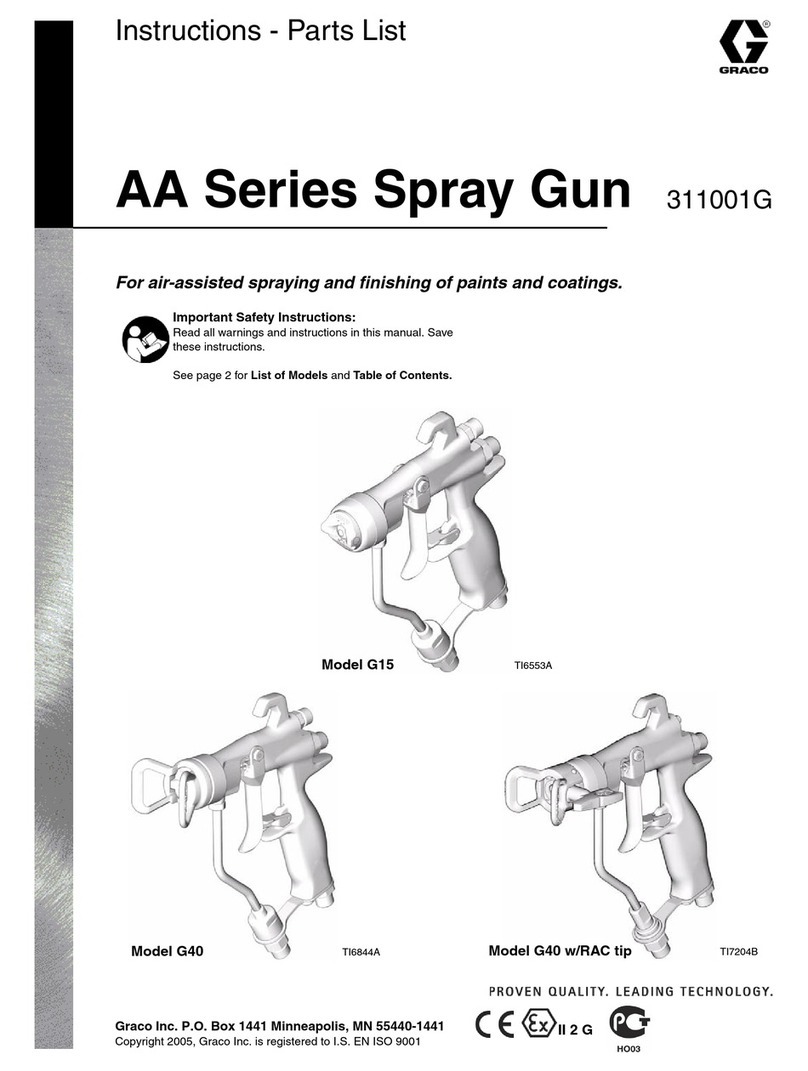
Graco AA Series Operation manual

Graco

Graco AA Series Operation manual

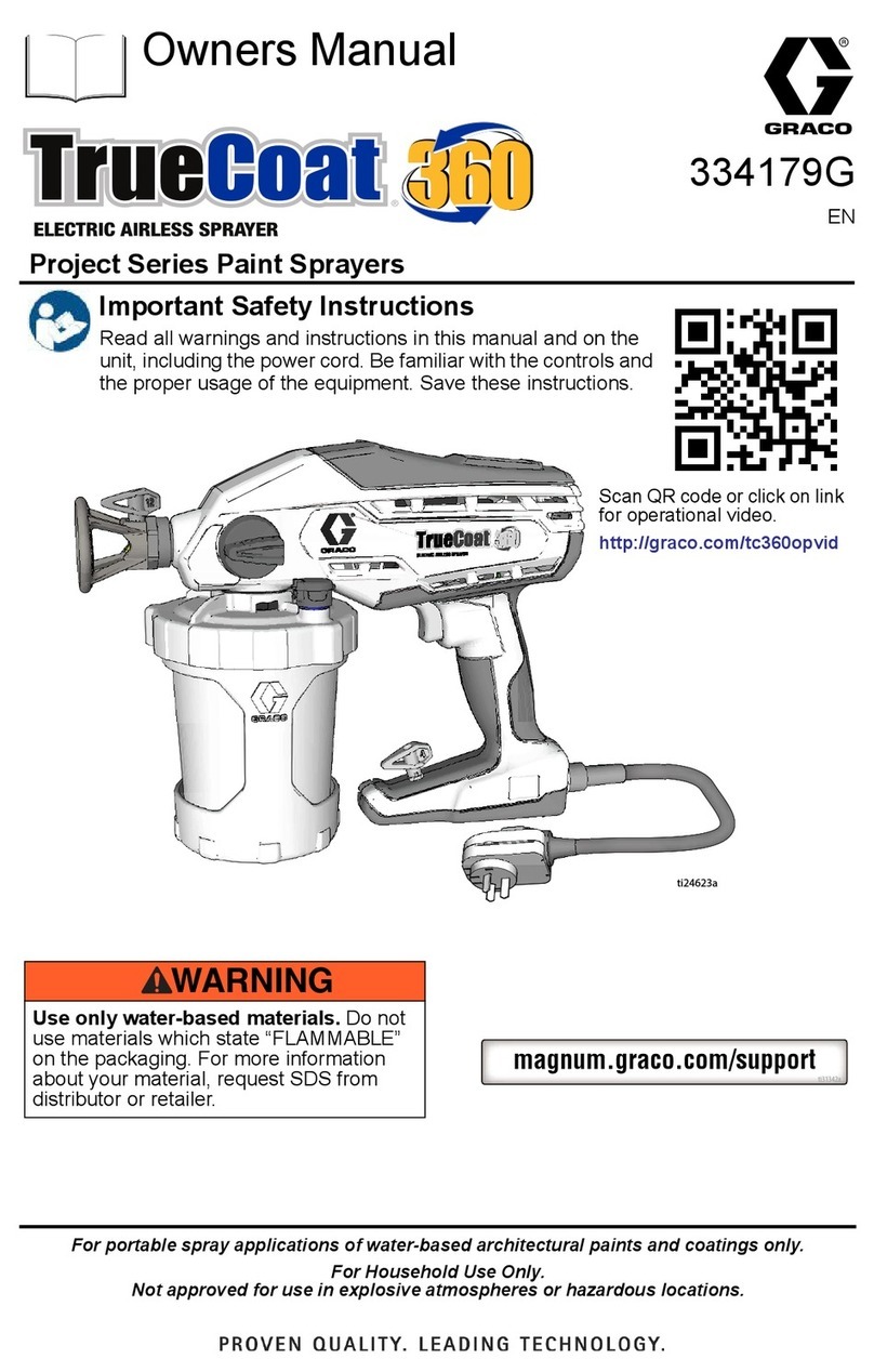
Graco TrueCoat 360 User manual

Graco

Graco TrueCoat 360 User manual

Graco Dura-Flo 600 User manual

Graco

Graco Dura-Flo 600 User manual

Graco HVLP 2500 User manual

Graco

Graco HVLP 2500 User manual

Graco 3A4803A Guide

Graco

Graco 3A4803A Guide

Graco 223-773 A Series Datasheet

Graco

Graco 223-773 A Series Datasheet

Graco UNICARB Pro AA4500 Operation manual

Graco

Graco UNICARB Pro AA4500 Operation manual

Graco 232900 User manual

Graco

Graco 232900 User manual

Graco Ultra Max II 695 User manual

Graco

Graco Ultra Max II 695 User manual

Graco Ultra Max II 695 Operation manual

Graco

Graco Ultra Max II 695 Operation manual

Graco G40 User manual

Graco

Graco G40 User manual

Graco LINE LAZER GM 5000 Series Datasheet

Graco

Graco LINE LAZER GM 5000 Series Datasheet

Graco 31-817 Operation manual

Graco

Graco 31-817 Operation manual

Graco JetRoller 25D229 Instruction Manual

Graco

Graco JetRoller 25D229 Instruction Manual

Graco ULTRA MAX II 1095 User manual

Graco

Graco ULTRA MAX II 1095 User manual

Graco EM 380 Operation manual

Graco

Graco EM 380 Operation manual

Graco Magnum X5 User manual

Graco

Graco Magnum X5 User manual

Graco FinishPro II 395 User manual

Graco

Graco FinishPro II 395 User manual

Graco 311286C Instruction Manual

Graco

Graco 311286C Instruction Manual

Graco 17C810 Use and care manual

Graco

Graco 17C810 Use and care manual

Graco GMax 5900 Instruction Manual

Graco

Graco GMax 5900 Instruction Manual

Popular Paint Sprayer manuals by other brands

Idex Akron Brass FS100 quick start guide

Idex

Idex Akron Brass FS100 quick start guide

mbp TEL 15BS instructions

mbp

mbp TEL 15BS instructions

Solo 425 Classic Original instructions

Solo

Solo 425 Classic Original instructions

WAGNER AirCoat GM 4100 AC operating manual

WAGNER

WAGNER AirCoat GM 4100 AC operating manual

Titan MultiFinish 440 owner's manual

Titan

Titan MultiFinish 440 owner's manual

SNOWJOE Sunjoe 24V-GS-LTW-RM Operator's manual

SNOWJOE

SNOWJOE Sunjoe 24V-GS-LTW-RM Operator's manual

Walther FSP-01 Assembly instructions

Walther

Walther FSP-01 Assembly instructions

Fimco LG-4-3-1 owner's manual

Fimco

Fimco LG-4-3-1 owner's manual

Nordson MicroMax 2 manual

Nordson

Nordson MicroMax 2 manual

Bonide 051 Operation and service instructions

Bonide

Bonide 051 Operation and service instructions

zogics Z-DAS instruction manual

zogics

zogics Z-DAS instruction manual

KISANKRAFT KK-KBS-165 Operation manual

KISANKRAFT

KISANKRAFT KK-KBS-165 Operation manual

Matrix SG 650 Translation of the original instructions

Matrix

Matrix SG 650 Translation of the original instructions

paasche VV Instructions and parts list

paasche

paasche VV Instructions and parts list

Carlisle DeVilbiss JGA-510 Service manual
Carlisle

Carlisle DeVilbiss JGA-510 Service manual
Gardena 11120 Operator's manual

Gardena

Gardena 11120 Operator's manual

DeVilbiss LUNA2i Operation manual

DeVilbiss

DeVilbiss LUNA2i Operation manual

WAGNER W 125 manual

WAGNER

WAGNER W 125 manual

manuals.online logo
manuals.online logoBrands
  • About & Mission
  • Contact us
  • Privacy Policy
  • Terms and Conditions

Copyright 2025 Manuals.Online. All Rights Reserved.

309317
Rev. A
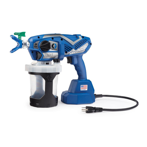
Cup Feed
Includes 1-quart (1 liter) cup
Model 244113, without fluid set
Model 244117, with # 3 fluid set
T10746
Remote Pressure Feed
Model 244115, without fluid set
Model 244118, with # 3 fluid set
INSTRUCTIONS
INSTRUCTIONS
This manual contains important
warnings and information.
READ AND KEEP FOR REFERENCE.
US Patent Pending
HVLP–Turbine Guns
10 psi (0.07 MPa, .7 bar) Maximum Inlet Air Pressure
50 psi (0.35 MPa, 3.5 bar) Maximum Inlet Fluid Pressure
Related Manuals
309205 – HVLP–Turbine Gun for maintenance and service instructions
309243 – HVLP Turbine
309244 – HVLP Compressor/Cart
GRACO INC. P.O. BOX 1441 MINNEAPOLIS, MN 55440–1441
ECOPYRIGHT 2001, GRACO INC.
Graco Inc. is registered to I.S. EN ISO 9001
2309317
Table of Contents
Symbols 2. . . . . . . . . . . . . . . . . . . . . . . . . . . . . . . . . . . . . .
Warnings 3. . . . . . . . . . . . . . . . . . . . . . . . . . . . . . . . . . . . . .
Component Identification 4. . . . . . . . . . . . . . . . . . . . . . . .
Setup 7. . . . . . . . . . . . . . . . . . . . . . . . . . . . . . . . . . . . . . . . .
Spray 7. . . . . . . . . . . . . . . . . . . . . . . . . . . . . . . . . . . . . . . . .
Shutdown 8. . . . . . . . . . . . . . . . . . . . . . . . . . . . . . . . . . . . .
Parts List 15. . . . . . . . . . . . . . . . . . . . . . . . . . . . . . . . . . . . .
Parts Drawing 14. . . . . . . . . . . . . . . . . . . . . . . . . . . . . . . . .
Technical Data 16. . . . . . . . . . . . . . . . . . . . . . . . . . . . . . . .
Graco Phone Number 18. . . . . . . . . . . . . . . . . . . . . . . . . .
Warning Symbol
WARNING
This symbol alerts you to the possibility of serious
injury or death if you do not follow instructions.
Caution Symbol
CAUTION
This symbol alerts you to the possibility of damage to
or destruction of equipment if you do not follow instruc-
tions.
You will need:
Cleaning fluids: a compatible solvent; water–based paint also requires soap and water.
Suggested proper clothing:
•Safety glasses •Sturdy boots or shoes
•Respirator •Gloves
TOXIC FLUID HAZARD: Hazardous fluid or toxic
fumes can cause serious injury or death if
splashed in eyes or on skin, inhaled, or swallowed.
DKnow specific hazards of fluid you are
using and take protective measures as
recommended by the fluid and solvent manufacturer.
Equipment Misuse Hazard: Equipment misuse
can cause the equipment to rupture or malfunction
and result in serious injury.
DBefore operating equipment, read all instruction
manuals, tags, and labels.
DCheck equipment daily. Repair or replace worn
or damaged parts immediately.
DDo not exceed maximum working pressure (MWPR) of the lowest–rated
system component
DUse fluids and solvents that are compatible with the equipment
wetted parts. See Specifications on page for this information.
DWear hearing protection when operating this equipment.
DDo not “blow back”fluid; this is not an air spray system
DFollow Pressure Relief before cleaning, checking or servicing the
equipment.
Fire and explosion hazard: Solvent and paint
fumes can ignite or explode.
DSprayers generate sparks. Keep sprayer at least
20 feet (6 m) from explosive vapors.
DUse in an extremely well ventilated area.
DEliminate all ignition sources; such as pilot lights,
cigarettes and static arcs from plastic drop cloths.
Do not plug or unplug power cords or turn lights
on or off in spray area.
DGround Sprayer, object being sprayed, paint and
solvent pails.
DDo not use 1,1,1-trichloroethane, methylene chlo-
ride, other halogenated hydrocarbon solvents or
fluids containing such solvents in pressurized alu-
minum equipment. Such use could result in a
chemical reaction, with the possibility of explosion.
3309317
4309317
Component Identification
D
Air inlet
Air cap/retaining ring –Adjusts
fan direction
Air flow control –Adjusts TOTAL
air flow to spray gun Pattern Adjustment Knob –
Adjusts pattern from fan to
round
Fluid flow/Pattern size control –
Adjusts fluid volume
Cup
Swivel tube and strainer
EasyGlidetTrigger
Duckbill check valve
5309317
PRESSURE RELIEF –Follow this procedure when cleaning, repairing or shuting down
sprayer
1. Turn off turbine. 2. Unlatch cup
TIP SELECTION
A Tip consists of a fluid
nozzle, and fluid needle.
Use the following chart
for recommendations.
Fluid Set Tip Size Fluid Usage
#2
244123 0.8 mm
(0.032 in) Ink, dye and non–wiping stain.
#3
244124 1.3 mm
(0.051 in) Water base lacquer, urethane, varnish, stain, and automotive finish.
#4
244125
1.8 mm
(0.071 in) Lacquer, urethane, varnish, stain, primer, enamel and epoxy.
#5
244126 2.2 mm
(0.087 in) Lacquer, urethane, varnish, stain, primer, enamel, epoxy and
higher output industrial finishes.
#6
244127 2.5 mm
(0.098 in) Latex, multi–spec, oil wall paint, industrial finishes, buty-
rate, and nitrate dope.
Installing the Fluid Set
Trigger the gun whenever you tighten or remove the nozzle. This keeps the needle seat away from
the nozzle seating surface and prevents the seat from being scratched.
CAUTION
For Cup Guns
Follow these
instructions whenever
you stop spraying.
1. Turn off air supply to the pot.
2 quart
8069A 0288
2
For Pressure Feed Guns
2. Open pressure relief (A) on
pot until pressure is completely
relieved. Close relief.
AA
Follow these
instructions whenever
you stop spraying.
6309317
1. Use your hand to loosen and remove the air cap retaining ring
and air cap housing.
2. Test spray pattern and atomization while holding gun about 6
to inches (150 to 200 mm) from test piece.
3. While triggering the gun, use your hand to loosen and remove the nozzle.
4. Use your hand to loosen and remove the fluid knob assembly and
compression ring from the back of the gun and remove the old needle.
5. Insert the needle assembly in the back of the gun. Reassemble nozzle, air cap housing and air cap re-
taining ring. Hand tighten.
Note: Nozzle should always have an o–ring (A).
.
A
7309317
6. Connect air hose to gun and turbine.
7. For cup gun, turn fluid control out until trigger movement is not restricted.
Caution: Turning knob too far will remove it.
Setup
8. Reduce and test catalyze all paint to manufacturer’s specifications.
SIf no reduction instructions are given, mix the fluid thoroughly, then gradually mix in reducer. To check
the consistency of the fluid. Remove the stir stick from the thinned paint. When the paint streaming off
the stick breaks into droplets, the first few drops should be one second apart.
STo compensate for faster drying time of turbine systems, use a reducer one step slower than used for
conventional air spray systems.
9. Remove cup. Fill 3/4 full. DO NOT OVERFILL. Reattach and latch cup.
For remote pressure pot, hold gun parallel to floor and adjust fluid pressure
to an 8 to 10 inch (203 to 254 mm) fluid stream.
NOTE: Heavier fluids or longer fluid hoses require greater pressures.
8309317
10. Plug turbine power cord into a grounded outlet.
SPRAY
11. Open air control valve.
12. Turn turbine on. Wait several minutes prior
to spraying to allow warm–up time.
13. Turn air cap to obtain desired direction.
9309317
air control
14. Lock air cap with retaining ring.
15. Select spray pattern by adjusting the fluid knob
and pattern selection knob. The air control ad-
justs the TOTAL air to the pattern and gun.
Retainingring
Nozzle
Air cap
pattern selection
knob
fluid knob
16. Hold gun perpendicular, 6–8 inches from surface. Move
gun first, then pull gun trigger to spray.
RoundPattern
Set knob to RND
Vertical Pattern
Set knob to FAN
Horizontal Pattern
Set knob to FAN
Note: If fluid is not atomizing properly, fluid may need to be thinned further, or a different tip size may be used.
10 309317
17. To control over–spray, reduce air flow or reduce fluid volume.
Note: If fluid is not atomizing properly, fluid may need to be thinned further, or a different
tip size may be used.
Swivel Tube Adjustment
The adjustable swivel tube allows the HVLP–Turbine Gun to be held in any position why spraying. To adjust the
position of the tube in the cup:
1. Loosen the nut (A) with a wrench (42).
2. Rotate the cup to the desired spray position.
3. Retighten the nut (A) with a wrench (42).
Swivel tube positioned
for spraying UP
Swivel tube positioned
for spraying DOWN
A
cup
swivel tube
A
swivel tube