7308717
Preparation
Grounding and Electrical Requirements
WARNING
Improper installation or alteration of the grounding
plug will result in a risk of electric shock, fire or
explosion that could cause serious injury or death.
Extension Cords
DUse only an extension cord with an undamaged,
3-prong plug.
DFor up to 25 ft (7.6 m) cord, use 3-wire, 12 AWG
(1.5 mm2) minimum.
DFor 25 to 50 ft (7.6 to 15.2 m) cords, use 3-wire,
10 AWG (2.5 mm2) minimum.
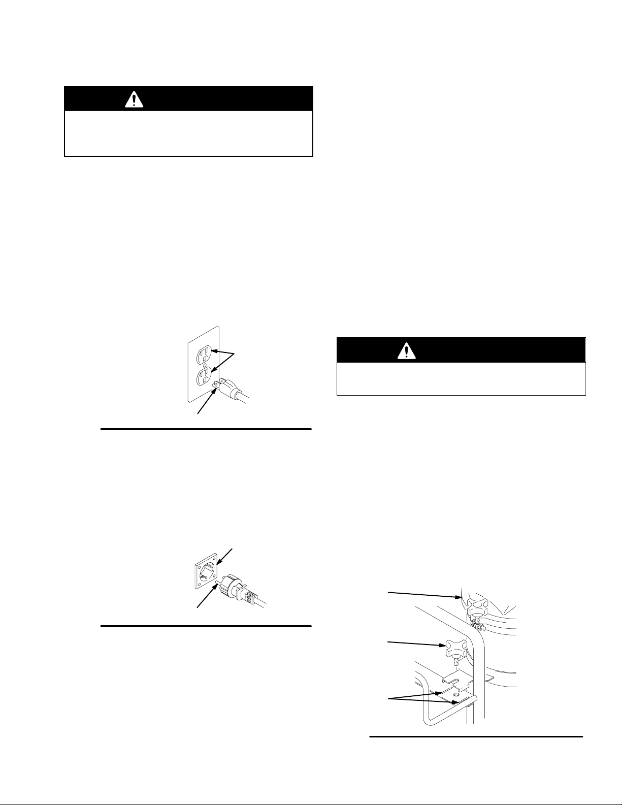
120V AC Systems
DThis equipment requires a 120V AC, 60 Hz, 15A
circuit with a grounding receptacle. See Fig. 4.
Fig. 4
grounding prong
grounded
outlets
DDo not alter the ground prong or use an adapter.
DA maximum length of 25 ft, 12 AWG or 50 ft,
10 AWG extension cord may be used.
240V AC Systems
DThis equipment requires a 240V AC, 50 Hz, 16A
circuit with a grounding receptacle. See Fig. 5.
Fig. 5
grounded
outlet
grounding prong 9248A
DDo not alter the ground prong or use an adapter.
DA maximum length of 8 m, 1.5 mm2or 15 m,
2.5 mm2extension cord may be used.
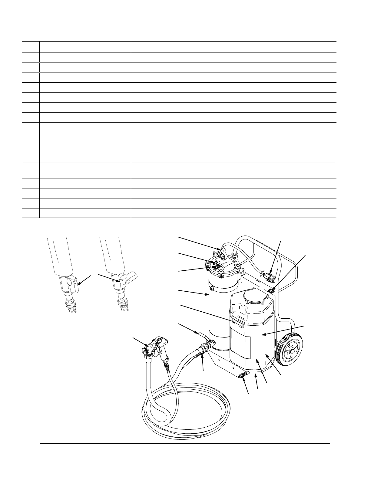
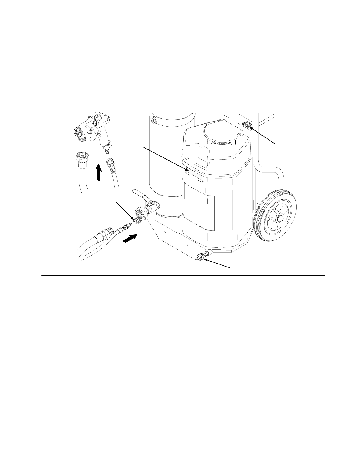
Hose Size and Lengths
The system comes with a hose set consisting of a 1 in.
ID x 25 ft (25 mm x 7.6 m) fluid hose and a 3/8 in. ID
air hose. The 1 in. hose set includes an adapter hose
between the gun and main hose. See Parts List on
page 23.
Do not use more than 75 ft (23 m) of fluid hose.
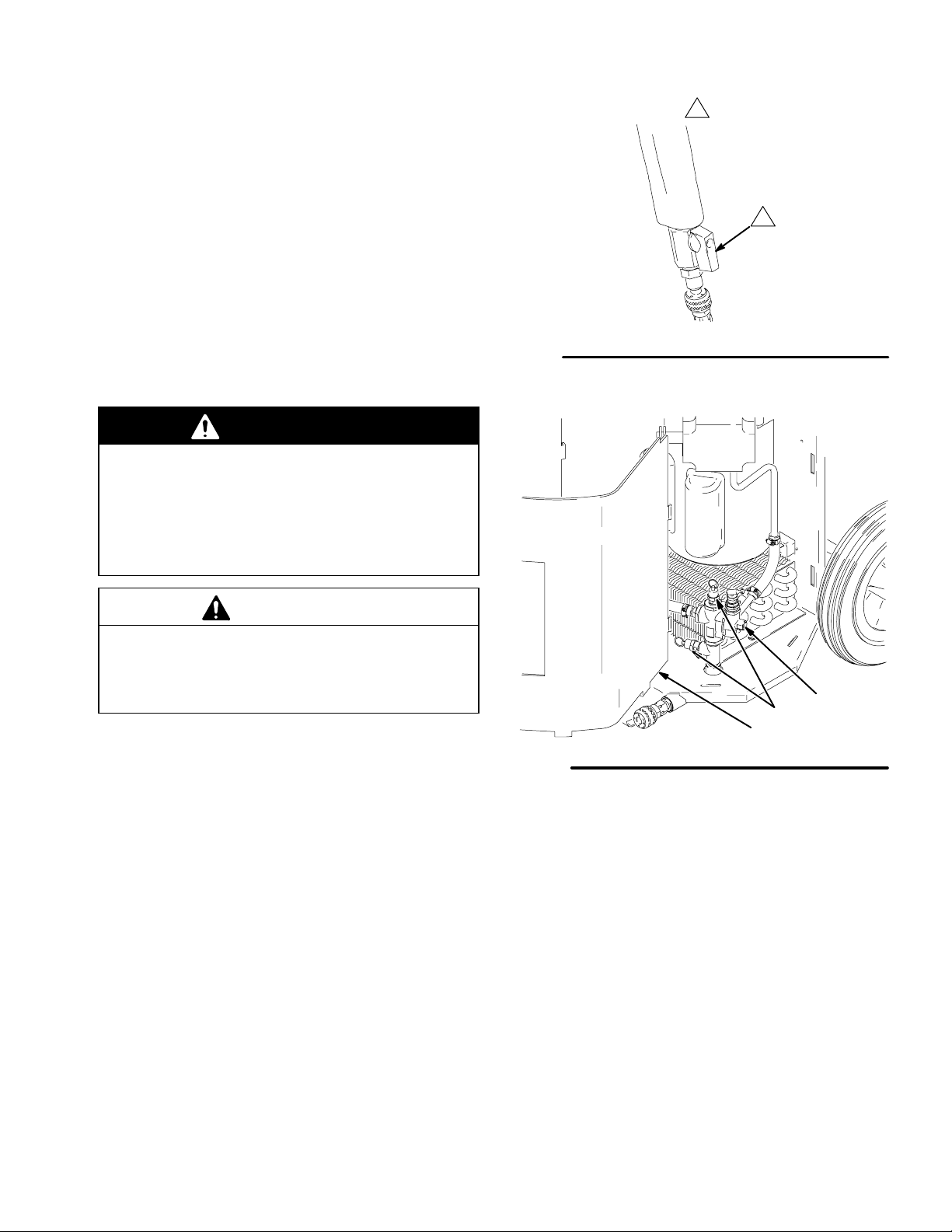
Auxiliary Air Compressor
An external air compressor may be connected
(adapter included) to the auxiliary air compressor port
(L) to supplement, or replace, the internal air
compressor of the TexSpray. This may be useful when
DAdditional air is needed to break up hard-to-spray
materials
DWhen the job site does not have the proper electric
service, but a gasoline-powered compressor is
available
WARNING
Over pressurizing the system may cause compo-
nent rupture and resulting in serious injury.
To reduce the risk of over pressurizing the system, do
not use a compressor with an output pressure greater
than 100 psi (70 kPa, 7 bar), and/or with a delivery
greater than 6.8 scfm at 90 psi (0.19 m3/min. at
60.3 kPa, 6.3 bar).
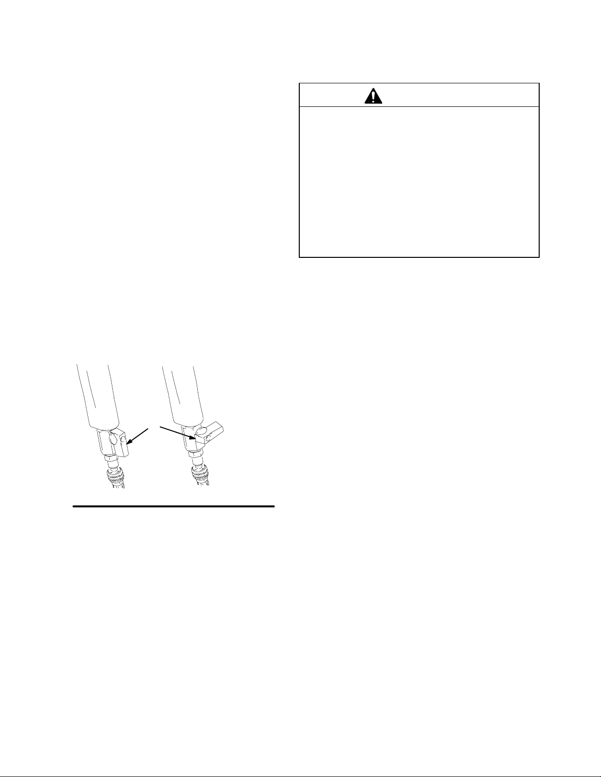
Removing and Installing the Pressure Pot
1. To remove the pressure pot (F), loosen the knob
(T) so that about 1 in. of the threads are showing.
Lift the pot off the unit. See Fig. 6.
2. To install the pressure pot, align bracket over slots
(S) and set it on the plastic base. Tighten the knob
(T). See Fig. 6.
Fig. 6
S
F
7124A
T