manuals.online logo
Brands
  1. Home
  2. •
  3. Brands
  4. •
  5. Graco
  6. •
  7. Water Pump
  8. •
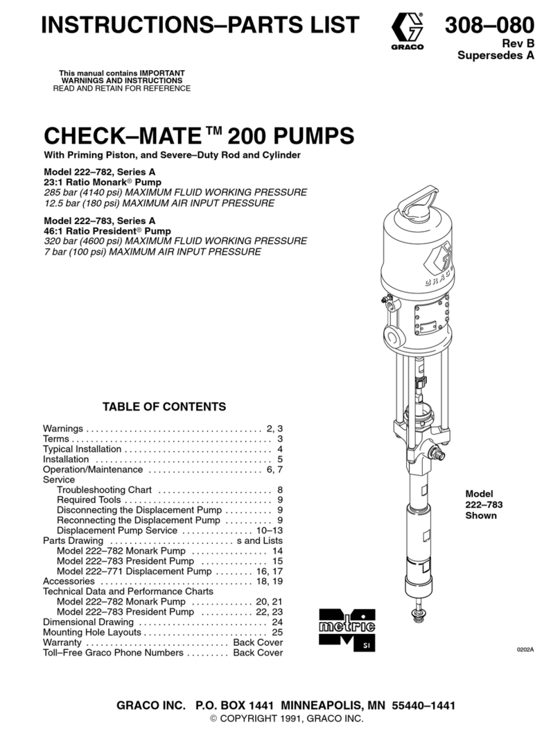
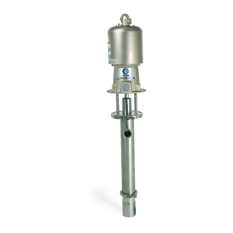
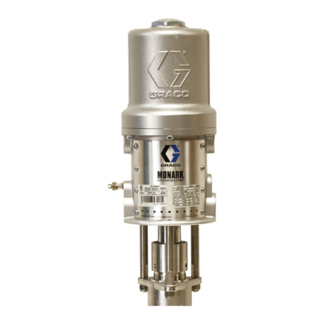
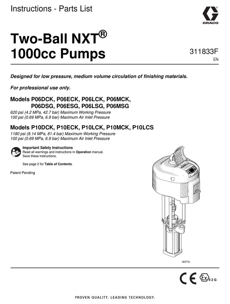
  9. Graco saniforce 2150 Use and care manual

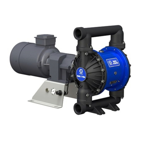
Graco saniforce 2150 Use and care manual

Repair/Parts
SaniForce® SaniForce®
SaniForce®2150, 2150,
2150,3000, 3000,
3000,4000, 4000,
4000,
Electric Electric
Electric- -
-Operated Operated
OperatedDiaphragm Diaphragm
DiaphragmPump Pump
Pump3A5133M 3A5133M
3A5133M
EN EN
EN
2 2
2- -
-Inch, Inch,
Inch,3 3
3- -
-Inch, Inch,
Inch,and and
and4 4
4- -
-Inch Inch
Inchpumps pumps
pumpswith with
withelectric electric
electricdrive drive
drivefor for
for󰘱uid 󰘱uid
󰘱uidtransfer transfer
transferapplications. applications.
applications.
Not Not
Notapproved approved
approvedfor for
foruse use
usein in
inexplosive explosive
explosiveatmospheres atmospheres
atmospheresor or
orhazardous hazardous
hazardous(classi󰘰ed) (classi󰘰ed)
(classi󰘰ed)locations locations
locationsunless unless
unlessotherwise otherwise
otherwise
stated. stated.
stated.See See
SeeApprovals Approvals
Approvalspage page
pagefor for
formore more
moreinformation. information.
information.For For
Forprofessional professional
professionaluse use
useonly. only.
only.
Important Important
ImportantSafety Safety
SafetyInstructions Instructions
Instructions
Readallwarningsandinstructionsinthismanualandinyour
Operationmanualbeforeusingtheequipment.Save Save
Savethese these
these
instructions. instructions.
instructions.
Formaximumworkingpressure,see
TechnicalSpeci󰘰cationsheets.
Seepage10forapprovals.
PROVENQUALITY.LEADINGTECHNOLOGY.
Contents Contents
Contents
Related Related
RelatedManuals Manuals
Manuals. .
.. .
.. .
.. .
.. .
.. .
.. .
.. .
.. .
.. .
.. .
.. .
.. .
.. .
.. .
.. .
.. .
.. .
.. .
.. .
.. .
.. .
.. .
.. .
.. .
.. .
.. .
.. .
.. .
.. .
.. .
.. .
.. .
.. .
.. .
.. .
.. .
.. .
.. .
.. .
.. .
.. .
.. .
.. .
.. .
.. .
.. .
.. .
.2 2
2
Warnings Warnings
Warnings. .
.. .
.. .
.. .
.. .
.. .
.. .
.. .
.. .
.. .
.. .
.. .
.. .
.. .
.. .
.. .
.. .
.. .
.. .
.. .
.. .
.. .
.. .
.. .
.. .
.. .
.. .
.. .
.. .
.. .
.. .
.. .
.. .
.. .
.. .
.. .
.. .
.. .
.. .
.. .
.. .
.. .
.. .
.. .
.. .
.. .
.. .
.. .
.. .
.. .
.. .
.. .
.. .
.. .
.. .
.. .
.. .
.. .
.. .
.3 3
3
Con󰘰guration Con󰘰guration
Con󰘰gurationNumber Number
NumberMatrix Matrix
Matrixfor for
for2150 2150
2150FG FG
FG
Pumps Pumps
Pumps. .
.. .
.. .
.. .
.. .
.. .
.. .
.. .
.. .
.. .
.. .
.. .
.. .
.. .
.. .
.. .
.. .
.. .
.. .
.. .
.. .
.. .
.. .
.. .
.. .
.. .
.. .
.. .
.. .
.. .
.. .
.. .
.. .
.. .
.. .
.. .
.. .
.. .
.. .
.. .
.. .
.. .
.. .
.. .
.. .
.. .
.. .
.. .
.. .
.. .
.6 6
6
Con󰘰guration Con󰘰guration
Con󰘰gurationNumber Number
NumberMatrix Matrix
Matrixfor for
for2150, 2150,
2150,3000, 3000,
3000,
and and
and4000 4000
4000HS HS
HSPumps Pumps
Pumps. .
.. .
.. .
.. .
.. .
.. .
.. .
.. .
.. .
.. .
.. .
.. .
.. .
.. .
.. .
.. .
.. .
.. .
.. .
.. .
.. .
.. .
.. .
.. .
.. .
.. .
.. .
.. .
.. .
.8 8
8
Approvals Approvals
Approvals. .
.. .
.. .
.. .
.. .
.. .
.. .
.. .
.. .
.. .
.. .
.. .
.. .
.. .
.. .
.. .
.. .
.. .
.. .
.. .
.. .
.. .
.. .
.. .
.. .
.. .
.. .
.. .
.. .
.. .
.. .
.. .
.. .
.. .
.. .
.. .
.. .
.. .
.. .
.. .
.. .
.. .
.. .
.. .
.. .
.. .
.. .
.. .
.. .
.. .
.. .
.. .
.. .
.. .
.. .
.. .
.. .
.. .
.. .
.10 10
10
Ordering Ordering
OrderingInformation Information
Information. .
.. .
.. .
.. .
.. .
.. .
.. .
.. .
.. .
.. .
.. .
.. .
.. .
.. .
.. .
.. .
.. .
.. .
.. .
.. .
.. .
.. .
.. .
.. .
.. .
.. .
.. .
.. .
.. .
.. .
.. .
.. .
.. .
.. .
.. .
.. .
.. .
.. .
.. .
.. .
.. .
.. .
.. .
.11 11
11
Troubleshooting Troubleshooting
Troubleshooting. .
.. .
.. .
.. .
.. .
.. .
.. .
.. .
.. .
.. .
.. .
.. .
.. .
.. .
.. .
.. .
.. .
.. .
.. .
.. .
.. .
.. .
.. .
.. .
.. .
.. .
.. .
.. .
.. .
.. .
.. .
.. .
.. .
.. .
.. .
.. .
.. .
.. .
.. .
.. .
.. .
.. .
.. .
.. .
.. .
.. .
.. .
.. .
.. .
.. .
.12 12
12
Repair Repair
Repair. .
.. .
.. .
.. .
.. .
.. .
.. .
.. .
.. .
.. .
.. .
.. .
.. .
.. .
.. .
.. .
.. .
.. .
.. .
.. .
.. .
.. .
.. .
.. .
.. .
.. .
.. .
.. .
.. .
.. .
.. .
.. .
.. .
.. .
.. .
.. .
.. .
.. .
.. .
.. .
.. .
.. .
.. .
.. .
.. .
.. .
.. .
.. .
.. .
.. .
.. .
.. .
.. .
.. .
.. .
.. .
.. .
.. .
.. .
.. .
.. .
.. .
.. .
.. .
.14 14
14
Pressure Pressure
PressureRelief Relief
ReliefProcedure Procedure
Procedure. .
.. .
.. .
.. .
.. .
.. .
.. .
.. .
.. .
.. .
.. .
.. .
.. .
.. .
.. .
.. .
.. .
.. .
.. .
.. .
.. .
.. .
.. .
.. .
.. .
.. .
.. .
.. .
.14 14
14
Check Check
CheckValve Valve
ValveRepair Repair
Repair. .
.. .
.. .
.. .
.. .
.. .
.. .
.. .
.. .
.. .
.. .
.. .
.. .
.. .
.. .
.. .
.. .
.. .
.. .
.. .
.. .
.. .
.. .
.. .
.. .
.. .
.. .
.. .
.. .
.. .
.. .
.. .
.. .
.. .
.. .
.. .
.. .
.14 14
14
Standard Standard
StandardDiaphragm Diaphragm
DiaphragmRepair Repair
Repair. .
.. .
.. .
.. .
.. .
.. .
.. .
.. .
.. .
.. .
.. .
.. .
.. .
.. .
.. .
.. .
.. .
.. .
.. .
.. .
.. .
.. .
.. .
.. .
.. .
.17 17
17
Overmolded Overmolded
OvermoldedDiaphragm Diaphragm
DiaphragmRepair Repair
Repair. .
.. .
.. .
.. .
.. .
.. .
.. .
.. .
.. .
.. .
.. .
.. .
.. .
.. .
.. .
.. .
.. .
.. .
.. .
.. .
.. .
.19 19
19
Center Center
CenterSection Section
SectionRepair Repair
Repair. .
.. .
.. .
.. .
.. .
.. .
.. .
.. .
.. .
.. .
.. .
.. .
.. .
.. .
.. .
.. .
.. .
.. .
.. .
.. .
.. .
.. .
.. .
.. .
.. .
.. .
.. .
.. .
.. .
.. .
.. .
.. .
.. .
.. .
.21 21
21
Install Install
InstallCompressor Compressor
CompressorKits Kits
Kits. .
.. .
.. .
.. .
.. .
.. .
.. .
.. .
.. .
.. .
.. .
.. .
.. .
.. .
.. .
.. .
.. .
.. .
.. .
.. .
.. .
.. .
.. .
.. .
.. .
.. .
.. .
.. .
.. .
.. .
.. .
.. .
.. .
.26 26
26
Replace Replace
Replacethe the
theCompressor Compressor
Compressor. .
.. .
.. .
.. .
.. .
.. .
.. .
.. .
.. .
.. .
.. .
.. .
.. .
.. .
.. .
.. .
.. .
.. .
.. .
.. .
.. .
.. .
.. .
.. .
.. .
.. .
.. .
.. .
.. .
.. .
.27 27
27
Parts Parts
Parts. .
.. .
.. .
.. .
.. .
.. .
.. .
.. .
.. .
.. .
.. .
.. .
.. .
.. .
.. .
.. .
.. .
.. .
.. .
.. .
.. .
.. .
.. .
.. .
.. .
.. .
.. .
.. .
.. .
.. .
.. .
.. .
.. .
.. .
.. .
.. .
.. .
.. .
.. .
.. .
.. .
.. .
.. .
.. .
.. .
.. .
.. .
.. .
.. .
.. .
.. .
.. .
.. .
.. .
.. .
.. .
.. .
.. .
.. .
.. .
.. .
.. .
.. .
.. .
.. .
.. .
.28 28
28
Kits Kits
Kitsand and
andAccessories Accessories
Accessories. .
.. .
.. .
.. .
.. .
.. .
.. .
.. .
.. .
.. .
.. .
.. .
.. .
.. .
.. .
.. .
.. .
.. .
.. .
.. .
.. .
.. .
.. .
.. .
.. .
.. .
.. .
.. .
.. .
.. .
.. .
.. .
.. .
.. .
.. .
.. .
.38 38
38
Technical Technical
TechnicalSpeci󰘰cations Speci󰘰cations
Speci󰘰cations. .
.. .
.. .
.. .
.. .
.. .
.. .
.. .
.. .
.. .
.. .
.. .
.. .
.. .
.. .
.. .
.. .
.. .
.. .
.. .
.. .
.. .
.. .
.. .
.. .
.. .
.. .
.. .
.. .
.. .
.. .
.. .
.. .
.. .
.. .
.. .
.. .
.. .
.39 39
39
Related Related
RelatedManuals Manuals
Manuals
ManualNumberTitle
3A5132SaniForce™2150,3000,4000,Electric-OperatedDiaphragmPump,Operation
23A5133M
Warnings
Warnings Warnings
Warnings
Thefollowingwarningsareforthesetup,use,grounding,maintenance,andrepairofthisequipment.The
exclamationpointsymbolalertsyoutoageneralwarningandthehazardsymbolsrefertoprocedure-speci󰘰c
risks.Whenthesesymbolsappearinthebodyofthismanualoronwarninglabels,referbacktothese
Warnings.Product-speci󰘰chazardsymbolsandwarningsnotcoveredinthissectionmayappearthroughout
thebodyofthismanualwhereapplicable.
DANGER
SEVERE SEVERE
SEVEREELECTRIC ELECTRIC
ELECTRICSHOCK SHOCK
SHOCKHAZARD HAZARD
HAZARD
Thisequipmentcanbepoweredbymorethan240V.Contactwiththisvoltagewill
causedeathorseriousinjury.
•Turnoffanddisconnectpoweratmainswitchbeforedisconnectinganycablesand
beforeservicingequipment.
•Thisequipmentmustbegrounded.Connectonlytogroundedpowersource.
•Allelectricalwiringmustbedonebyaquali󰘰edelectricianandcomplywithalllocal
codesandregulations.
WARNING
FIRE FIRE
FIREAND AND
ANDEXPLOSION EXPLOSION
EXPLOSIONHAZARD HAZARD
HAZARD
Flammablefumes,suchassolvent,inwork work
workarea area
areacanigniteorexplode.Solvent󰘱owingthrough
theequipmentcancausestaticsparking.Tohelpprevent󰘰reandexplosion:
•Useequipmentonlyinwellventilatedarea.
•Eliminateallignitionsources;suchaspilotlights,cigarettes,portableelectriclamps,and
plasticdropcloths(potentialstaticsparking).
•Groundallequipmentintheworkarea.SeeGrounding Grounding
Groundinginstructions.
•Keepworkareafreeofdebris,includingsolvent,ragsandgasoline.
•Donotplugorunplugpowercords,orturnpowerorlightswitchesonoroffwhen󰘱ammable
fumesarepresent.
•Useonlygroundedlines.
•Stop Stop
Stopoperation operation
operationimmediately immediately
immediatelyifstaticsparkingoccursoryoufeelashock. .
.Donotuse
equipmentuntilyouidentifyandcorrecttheproblem.
•Keepaworking󰘰reextinguisherintheworkarea.
Staticchargemaybuilduponplasticpartsduringcleaningandcoulddischargeandignite
󰘱ammablevapors.Tohelpprevent󰘰reandexplosion:
•Cleanplasticpartsonlyinwellventilatedarea.
•Donotcleanwithadrycloth.
3A5133M3
Warnings
WARNING
PRESSURIZED PRESSURIZED
PRESSURIZEDEQUIPMENT EQUIPMENT
EQUIPMENTHAZARD HAZARD
HAZARD
Fluidfromtheequipment,leaks,orrupturedcomponentscansplashintheeyesoronskin
andcauseseriousinjury.
•FollowthePressure Pressure
PressureRelief Relief
ReliefProcedure Procedure
Procedurewhenyoustopspraying/dispensingandbefore
cleaning,checking,orservicingequipment.
•Tightenall󰘱uidconnectionsbeforeoperatingtheequipment.
•Check󰘱uidlines,tubes,andcouplingsdaily.Replacewornordamagedpartsimmediately.
EQUIPMENT EQUIPMENT
EQUIPMENTMISUSE MISUSE
MISUSEHAZARD HAZARD
HAZARD
Misusecancausedeathorseriousinjury.
•Donotoperatetheunitwhenfatiguedorunderthein󰘱uenceofdrugsoralcohol.
•Donotexceedthemaximumworkingpressureortemperatureratingofthelowestrated
systemcomponent.SeeTechnical Technical
TechnicalSpeci󰘰cations Speci󰘰cations
Speci󰘰cationsinallequipmentmanuals.
•Use󰘱uidsandsolventsthatarecompatiblewithequipmentwettedparts.SeeTechnical Technical
Technical
Speci󰘰cations Speci󰘰cations
Speci󰘰cationsinallequipmentmanuals.Read󰘱uidandsolventmanufacturer’swarnings.
Forcompleteinformationaboutyourmaterial,requestSafetyDataSheet(SDS)from
distributororretailer.
•TurnoffallequipmentandfollowthePressure Pressure
PressureRelief Relief
ReliefProcedure Procedure
Procedurewhenequipmentisnotinuse.
•Checkequipmentdaily.Repairorreplacewornordamagedpartsimmediatelywithgenuine
manufacturer’sreplacementpartsonly.
•Donotalterormodifyequipment.Alterationsormodi󰘰cationsmayvoidagencyapprovals
andcreatesafetyhazards.
•Makesureallequipmentisratedandapprovedfortheenvironmentinwhichyouareusingit.
•Useequipmentonlyforitsintendedpurpose.Callyourdistributorforinformation.
•Route󰘱uidlinesandcablesawayfromtraf󰘰careas,sharpedges,movingparts,andhot
surfaces.
•Donotkinkoroverbend󰘱uidlinesoruse󰘱uidlinestopullequipment.
•Keepchildrenandanimalsawayfromworkarea.
•Complywithallapplicablesafetyregulations.
PRESSURIZED PRESSURIZED
PRESSURIZEDALUMINUM ALUMINUM
ALUMINUMPARTS PARTS
PARTSHAZARD HAZARD
HAZARD
Useof󰘱uidsthatareincompatiblewithaluminuminpressurizedequipmentcancauseserious
chemicalreactionandequipmentrupture.Failuretofollowthiswarningcanresultindeath,
seriousinjury,orpropertydamage.
•Donotuse1,1,1-trichloroethane,methylenechloride,otherhalogenatedhydrocarbon
solventsor󰘱uidscontainingsuchsolvents.
•Donotusechlorinebleach.
•Manyother󰘱uidsmaycontainchemicalsthatcanreactwithaluminum.Contactyourmaterial
supplierforcompatibility.
43A5133M
Warnings
WARNING
THERMAL THERMAL
THERMALEXPANSION EXPANSION
EXPANSIONHAZARD HAZARD
HAZARD
Fluidssubjectedtoheatincon󰘰nedspaces,includinglines,cancreatearapidriseinpressure
duetothethermalexpansion.Over-pressurizationcanresultinequipmentruptureandserious
injury.
•Openavalvetorelievethe󰘱uidexpansionduringheating.
•Replacelinesproactivelyatregularintervalsbasedonyouroperatingconditions.
PLASTIC PLASTIC
PLASTICPARTS PARTS
PARTSCLEANING CLEANING
CLEANINGSOLVENT SOLVENT
SOLVENTHAZARD HAZARD
HAZARD
Manysolventscandegradeplasticpartsandcausethemtofail,whichcouldcauseserious
injuryorpropertydamage.
•Useonlycompatiblesolventstocleanplasticstructuralorpressure-containingparts.
•SeeTechnical Technical
TechnicalSpeci󰘰cations Speci󰘰cations
Speci󰘰cationsinallequipmentmanualsformaterialsofconstruction.Consult
thesolventmanufacturerforinformationandrecommendationsaboutcompatibility.
•SeeTechnical Technical
TechnicalSpeci󰘰cations Speci󰘰cations
Speci󰘰cationsinthisandallotherequipmentinstructionmanuals.Read󰘱uid
andsolventmanufacturer’sSafetyDataSheet(SDS)andrecommendations.
TOXIC TOXIC
TOXICFLUID FLUID
FLUIDOR OR
ORFUMES FUMES
FUMESHAZARD HAZARD
HAZARD
Toxic󰘱uidsorfumescancauseseriousinjuryordeathifsplashedintheeyesoronskin,
inhaled,orswallowed.
•ReadSafetyDataSheet(SDS)toknowthespeci󰘰chazardsofthe󰘱uidsyouareusing.
•Storehazardous󰘱uidinapprovedcontainers,anddisposeofitaccordingtoapplicable
guidelines.
BURN BURN
BURNHAZARD HAZARD
HAZARD
Equipmentsurfacesand󰘱uidthat’sheatedcanbecomeveryhotduringoperation.Toavoid
severeburns:
•Donottouchhot󰘱uidorequipment.
PERSONAL PERSONAL
PERSONALPROTECTIVE PROTECTIVE
PROTECTIVEEQUIPMENT EQUIPMENT
EQUIPMENT
Wearappropriateprotectiveequipmentwhenintheworkareatohelppreventseriousinjury,
includingeyeinjury,hearingloss,inhalationoftoxicfumes,andburns.Thisprotective
equipmentincludesbutisnotlimitedto:
•Protectiveeyewear,andhearingprotection.
•Respirators,protectiveclothing,andglovesasrecommendedbythe󰘱uidandsolvent
manufacturer.
3A5133M5
CongurationNumberMatrixfor2150FGPumps
Con󰘰guration Con󰘰guration
Con󰘰gurationNumber Number
NumberMatrix Matrix
Matrixfor for
for2150 2150
2150FG FG
FGPumps Pumps
Pumps
Checktheidenti󰘰cationplate(ID)forthe
Con󰘰gurationNumberofyourpump.Usethe
followingmatrixtode󰘰nethecomponentsofyour
pump.
Whenyoureceiveyourpump,recordthe9character
partnumberfoundontheshippingbox(e.g.,
SP1B.0014):
_____________
Alsorecordthecon󰘰gurationnumberonthepumpID
platetoassistyouwhenorderingreplacementparts:
_____________________________________
Sample Sample
SampleCon󰘰guration Con󰘰guration
Con󰘰gurationNumber: Number:
Number:2150FG 2150FG
2150FG- -
-EA04AS13SSPTPTPT21 EA04AS13SSPTPTPT21
EA04AS13SSPTPTPT21
2150 2150
2150FG FG
FGE E
EA A
A04 04
04A A
AS13 S13
S13SS SS
SSPT PT
PTPT PT
PTPT PT
PT21 21
21
Pump
Model
Wetted
Section
DriveCenter
Section
Gear
Boxand
Compressor
MotorFluidCoversand
Manifolds
SeatsBalls
orChe-
cks
DiaphragmsManifold
Seals
Certi󰘰ca-
tion
Pump Pump
PumpWetted Wetted
WettedSection Section
SectionDrive Drive
DriveType Type
TypeCenter Center
CenterSection Section
Section
Material Material
Material
Gearbox Gearbox
Gearboxand and
and
Compressor Compressor
Compressor
Motor Motor
Motor
2150 2150
2150FG FG
FGFoodGradeE E
EElectricA A
AAluminum94 94
94NoGearboxor
CompressorA A
AStandard
InductionMotor
S S
SStainlessSteel04 04
04HighSpeedGear
RatioC C
CATEXInduction
Motor
05 05
05HighSpeed
GearRatio/120V
Compressor
D D
DFlameproof
InductionMotor
06 06
06HighSpeed
GearRatio/240V
Compressor
G G
GNoMotor
14 14
14MidSpeedGear
Ratio
15 15
15MidSpeed
GearRatio/120V
Compressor
16 16
16MidSpeed
GearRatio/240V
Compressor
24 24
24LowSpeedGear
Ratio
25 25
25LowSpeed
GearRatio/120V
Compressor
26 26
26LowSpeed
GearRatio/240V
Compressor
63A5133M
CongurationNumberMatrixfor2150FGPumps
Fluid Fluid
FluidCovers Covers
Coversand and
and
Manifolds Manifolds
Manifolds
Seat Seat
SeatMaterial Material
MaterialBall Ball
Ballor or
orCheck Check
Check
Material Material
Material
Diaphragm Diaphragm
DiaphragmMaterial Material
MaterialManifold Manifold
Manifold
Seals Seals
Seals
Certi󰘰cation Certi󰘰cation
Certi󰘰cation
S13 S13
S13Stainless
steel,
TriClamp
SS SS
SS316
Stainless
Steel
CW CW
CWPolychloro-
prene
Weighted
PT PT
PTPTFE/EPDM
2-PieceEP EP
EPEPDMblanknocerti󰘰cation
S14 S14
S14Stainless
steel,DINPT PT
PTPTFESP SP
SPSanto-
prene/EPDM
2–Piece
PT PT
PTPTFE21 21
21EN10204type
2.1
SP SP
SPSantoprene31 31
31EN10204type
3.1
3A5133M7
CongurationNumberMatrixfor2150,3000,and4000HSPumps
Con󰘰guration Con󰘰guration
Con󰘰gurationNumber Number
NumberMatrix Matrix
Matrixfor for
for2150, 2150,
2150,3000, 3000,
3000,and and
and4000 4000
4000
HS HS
HSPumps Pumps
Pumps
Checktheidenti󰘰cationplate(ID)forthe
Con󰘰gurationNumberofyourpump.Usethe
followingmatrixtode󰘰nethecomponentsofyour
pump.
Whenyoureceiveyourpump,recordthe9character
partnumberfoundontheshippingbox(e.g.,
SP1B.0014):
_____________
Alsorecordthecon󰘰gurationnumberonthepumpID
platetoassistyouwhenorderingreplacementparts:
_____________________________________
Sample Sample
SampleCon󰘰guration Con󰘰guration
Con󰘰gurationNumber: Number:
Number:2150HS 2150HS
2150HS- -
-ES04ASSASSPTPSEP21 ES04ASSASSPTPSEP21
ES04ASSASSPTPSEP21
2150 2150
2150HS HS
HSE E
ES S
S04 04
04A A
ASSA SSA
SSASS SS
SSPT PT
PTPS PS
PSEP EP
EP21 21
21
Pump
Model
Wetted
Section
DriveCenter
Section
Gear
Boxand
Compressor
MotorFluidCoversand
Manifolds
SeatsBalls
orChe-
cks
DiaphragmsManifold
Seals
Certi󰘰ca-
tion
Pump Pump
PumpWetted Wetted
WettedSection Section
SectionDrive Drive
DriveType Type
TypeCenter Center
CenterSection Section
Section
Material Material
Material
Gearbox Gearbox
Gearboxand and
and
Compressor Compressor
Compressor
Motor Motor
Motor
2150 2150
2150HS HS
HSHighSanitationE E
EElectricS S
SStainlessSteel94 94
94NoGearboxor
CompressorA A
AStandard
InductionMotor
3000 3000
30003A 3A
3A3ACerti󰘰ed04 04
04HighSpeedGear
RatioC C
CATEXInduction
Motor
4000 4000
4000PH PH
PHPharmaceutical05 05
05HighSpeed
GearRatio/120V
Compressor
D D
DFlameproof
InductionMotor
06 06
06HighSpeed
GearRatio/240V
Compressor
G G
GNoMotor
14 14
14MidSpeedGear
Ratio
15 15
15MidSpeed
GearRatio/120V
Compressor
16 16
16MidSpeed
GearRatio/240V
Compressor
24 24
24LowSpeedGear
Ratio
25 25
25LowSpeed
GearRatio/120V
Compressor
26 26
26LowSpeed
GearRatio/240V
Compressor
83A5133M
CongurationNumberMatrixfor2150,3000,and4000HSPumps
Fluid Fluid
FluidCovers Covers
Coversand and
and
Manifolds Manifolds
Manifolds
Seat Seat
SeatMaterial Material
MaterialBall Ball
Ballor or
orCheck Check
Check
Material Material
Material
Diaphragm Diaphragm
DiaphragmMaterial Material
MaterialManifold Manifold
Manifold
Seals Seals
Seals
Certi󰘰cation Certi󰘰cation
Certi󰘰cation
SSA SSA
SSAStainless
Steel,
Tri-Clamp
(HS/3-A/
PH)
FL FL
FL316
Stainless
Steel
Flapper
— —
—Flapper,check,
StainlessSteelBN BN
BNBuna-NBN BN
BNBuna-N21 21
21EN10204type
2.1
SSB SSB
SSBStainless
Steel,DIN
(HS/3-
A/PH)
SS SS
SS316
Stainless
Steel
BN BN
BNBuna-NEO EO
EOEPDM
OvermoldedEP EP
EPEPDM31 31
31EN10204type
3.1
CW CW
CWPolychloro-
prene
Weighted
FK FK
FKFKM
FluoroelastomerFK FK
FKFKM
FK FK
FKFKMFluoroe-
lastomerPS PS
PSPTFE/Santo-
prene2-Piece
PT PT
PTPTFESP SP
SPSanto-
prene/EPDM
2Piece
SP SP
SPSantoprene
3A5133M9
Approvals
Approvals Approvals
Approvals
Approvals Approvals
Approvals
✦PumpswithmotorcodeCareapprovedto:
II2G
ExhdIIBT3Gb
✚PumpswithmotorcodeGareapprovedto:
II2G
ExhIIBT3Gb
★MotorscodedDareapprovedto:
ClassI,Div1,GroupD,T3B
ClassII,Div1,GroupF&G,T3B
DiaphragmmaterialscodedEO,PT,orPS
combinedwithcheckmaterialscodedFLor
PTcomplywith:
EC1935/2004
AllModels(exceptgearboxandcompressor
codes05,15,and25,ormotorcodeD)are
approvedto:
DiaphragmmaterialscodedEO,PTorPS
combinedwithcheckmaterialscodedFLor
PTcomplywith:
ClassVI
All󰘱uidcontactmaterialsareFDA-compliant
andmeettheUnitedStatesCodeofFederal
Regulations(CFR).
103A5133M
OrderingInformation
Ordering Ordering
OrderingInformation Information
Information
To To
ToFind Find
FindYour Your
YourNearest Nearest
NearestDistributor Distributor
Distributor
Visitwww.graco.com
To To
ToSpecify Specify
Specifythe the
theCon󰘰guration Con󰘰guration
Con󰘰gurationof of
ofa a
aNew New
NewPump Pump
Pump
Please Please
Pleasecall call
callyour your
yourdistributor. distributor.
distributor.
OR OR
OR
UsetheOnline Online
OnlineDiaphragm Diaphragm
DiaphragmPump Pump
PumpSelector Selector
SelectorTool Tool
Toolat at
atwww.graco.com www.graco.com
www.graco.com. .
.SearchforSelector Selector
Selector.
To To
ToOrder Order
OrderReplacement Replacement
ReplacementParts Parts
Parts
Please Please
Pleasecall call
callyour your
yourdistributor. distributor.
distributor.
3A5133M11
Troubleshooting
Troubleshooting Troubleshooting
Troubleshooting
•FollowthePressureReliefProcedure,page14,
beforecheckingorservicingtheequipment.
•Checkallpossibleproblemsandcausesbefore
disassembly.
Problem Problem
ProblemCause Cause
CauseSolution Solution
Solution
Pumpisrunningtoofast,causing
cavitationbeforeprime.
Slowdownthecontroller(VFD)
Centersectionhasnoairpressure,
orairpressureistoolow.
Applyairpressuretocentersection
peryourapplicationrequirements.
Checkvalveballisseverelywornor
wedgedinseatormanifold.
Replacetheballandseat.
Thepumphasinsuf󰘰cientsuction
pressure.
Increasethesuctionpressure.See
theOperationmanual.
Seatisseverelyworn.Replacetheballandseat.
Outletorinletisrestricted.Removetherestriction.
Inlet󰘰ttingsormanifoldsareloose.Tighten.
Pumpcyclesbutwillnot
primeand/orpump.
Manifoldo-ringsaredamaged.Replaceo-rings.
Thecentersectionis
excessivelyhot.
Thedriveshaftisbroken.Replace.
Checkvalveballs,seats,oro-rings
areworn.
Replace.
Manifoldscrewsor󰘱uidcover
screwsareloose.
Tighten.
Diaphragmshaftboltisloose.Tighten.
Pumpfailstohold󰘱uid
pressureatstall.
NOTE: NOTE:
NOTE:Flapperchecks
arenot100%󰘱uidtight.
Flapvalvesinstalledupside-down.Installthe󰘱appervalvewiththetext
sidefacingtheseat.
Motororcontrolleriswired
improperly.
Wirepermanual. Pumpwillnotcycle.
Theleakdetector(ifinstalled)has
tripped.
Checkdiaphragmforruptureor
incorrectinstallation.Repairor
replace.
Themotorisoperating,
butthepumpwillnot
cycle.
Thejawcouplingbetweenthe
motorandgearboxisnotconnected
properly.
Checktheconnection.
Suctionlineisclogged.Inspect;clear.
Checksarestickyorleaking.Cleanorreplace.
Pump󰘱owrateiserratic.
Diaphragm(orbackup)ruptured.Replace.
Pumpmakesunusual
noises.
Pumpisoperatingnearoratstall
pressure.
Adjustairpressureorslowthepump
speed.
123A5133M
Troubleshooting
Problem Problem
ProblemCause Cause
CauseSolution Solution
Solution
A󰘰ttingisloose.Tighten.Inspectthreadsealant.
Looseordamagedo-ringsorshaft
seal.
Replace.
Airconsumptionishigher
thanexpected.
Diaphragm(orbackup)ruptured.Replace.
Suctionlineisloose.Tighten.
Diaphragm(orbackup)ruptured.Replace.
Loosemanifolds,damagedseatsor
o-rings.
Tightenmanifoldboltsorreplace
seatsoro-rings.
Airbubblesin󰘱uid.
Loosediaphragmshaftbolt.Tighten.
Loosemanifoldscrewsor󰘱uidcover
screws.
Tighten.
Pumpleaks󰘱uid
externallyfromjoints.
Manifoldo-ringswornout.Replaceo-rings.
AGFCIhastripped.Removethecontrollerfromthe
GFCIcircuit.
Supplypowerispoor.Determineand󰘰xthesourceofthe
powerproblem.
Thecontrollerfaultsor
shutsdown.
Operationalparametersare
exceeded.
Seeperformancechart;ensure
pumpisoperatingwithinthe
continuousdutyrange.
Inletcheckclogged/improperly
installed
Removedebris/installproperly Excessivemotor
regenerationfaultfrom
VFDBrokendiaphragmboltReplacebolt
NOTE: NOTE:
NOTE:ForproblemswithaVariableFrequencyDevice(VFD),seeyourVFDmanual.
3A5133M13
Repair
Repair Repair
Repair
NOTE: NOTE:
NOTE:Whenreassembling󰘱uidsectioncomponents,
looselyassembleinitiallytoensureacceptable
alignment.Onceallcomponentsareinplace,tighten
allclamps.
Pressure Pressure
PressureRelief Relief
ReliefProcedure Procedure
Procedure
FollowthePressureReliefProcedure
wheneveryouseethissymbol.
Thisequipmentstayspressurizeduntilpressureis
manuallyrelieved.Tohelppreventseriousinjury
frompressurized󰘱uid,suchassplashing󰘱uid,
followthePressureReliefProcedurewhenyou
stopdispensingandbeforecleaning,checking,or
servicingtheequipment.
1.Turnoffthepumpanddisconnectpowertothe
system.
2.Closethemasterairvalve(J)toshutofftheair
tothepump.
3.Openthe󰘱uiddrainvalve(L)torelieve󰘱uid
pressure.Haveacontainerreadytocatchthe
drainage.
4.Closethepumpairinletport(E)onthepneumatic
enclosure.
Check Check
CheckValve Valve
ValveRepair Repair
Repair
Tools Tools
ToolsRequired Required
Required
•O-ringpick
NOTE: NOTE:
NOTE:Kitsareavailablefornewcheckvalveballs
andseatsinarangeofmaterials.O-ringkitsalso
areavailable.
NOTE: NOTE:
NOTE:Toensureproperseatingofthecheckballs,
alwaysreplacetheseatswhenreplacingtheballs.
Also,replacetheo-ringseverytimethemanifoldis
removed.
Disassemble Disassemble
Disassemblethe the
theBall Ball
BallCheck Check
CheckValve Valve
Valve
1.FollowthePressureReliefProcedure,page14.
Disconnectpowerfromthemotor.Disconnectall
󰘱uidandairlines.
2.Removetheclamps(31)holdingtheoutlet
manifold(3)tothe󰘱uidcovers(2),thenremove
theoutletmanifold.
3.Removetheballcheckvalveassemblies:
a.Onthe2150FG,removetheseats(6),balls
(7),ando-rings(8).
b.Onthe2150HS,removetheballstops(28),
balls(7),andgaskets(8a).
4.Repeatfortheinletmanifold.
5.Tocontinuewithdiaphragmdisassembly,see
DisassembletheStandardDiaphragms,page17.
Reassemble Reassemble
Reassemblethe the
theBall Ball
BallCheck Check
CheckValve Valve
Valve
1.Cleanallpartsandinspectforwearordamage.
Replacepartsasneeded.
2.Reassembleinthereverseorder,followingall
notesintheillustration.Puttheinletmanifoldon
󰘰rst.Besuretheballchecksandmanifoldsare
assembledexactly exactly
exactlyasshown.Ifpresentonthe
󰘱uidcovers(2),thearrows(A)must must
mustpointtoward
theoutletmanifold(3).For󰘱uidcoverswithout
arrows,thetallestopeninginthe󰘱uidcovermust must
must
beattachedtotheoutletmanifold.
143A5133M
Repair
1
Arrow(A)mustpointtowardoutlet
manifold.
2
Radiusedseatingsurfacemustfacethe
ball(7).LargechampferonO.D.mustface
o-ring.
3A5133M15
Repair
Disassemble Disassemble
Disassemblethe the
theFlapper Flapper
FlapperCheck Check
CheckValve Valve
Valve
1.FollowthePressureReliefProcedure,page14.
Disconnectpowerfromthemotor.Disconnectall
󰘱uidandairlines.
2.Removetheclamps(31)holdingtheoutlet
manifold(3)tothe󰘱uidcovers,thenremovethe
outletmanifold.
3.Removethe󰘱appers(7a),andgaskets(8a).
4.Repeatstepstoremovetheinletmanifold(4).
Removethe󰘱appers(7a),andgaskets(8a).
5.Tocontinuewithdiaphragmdisassembly,see
DisassembletheStandardDiaphragms,page17.
Reassemble Reassemble
Reassemblethe the
theFlapper Flapper
FlapperCheck Check
CheckValve Valve
Valve
1.Cleanallpartsandinspectforwearordamage.
Replacepartsasneeded.
2.Reassembleinthereversedisassemblyorder.
Puttheinletmanifoldon󰘰rst.Besurethe󰘱apper
checksandmanifoldsareassembledexactly exactly
exactlyas
shown.
NOTE: NOTE:
NOTE:Installthe󰘱appervalves(7a)withthetext
sidefacingtheseat.
163A5133M
Repair
Standard Standard
StandardDiaphragm Diaphragm
DiaphragmRepair Repair
Repair
Tools Tools
ToolsRequired Required
Required
•Torquewrench
•10mmhexkeywrench
•28mmopenendwrench
•O-ringpick
Disassemble Disassemble
Disassemblethe the
theStandard Standard
StandardDiaphragms Diaphragms
Diaphragms
NOTE: NOTE:
NOTE:Diaphragmkitsareavailableinarangeof
materialsandstyles.SeePartssection.
1.FollowthePressureReliefProcedure,page14.
Disconnectpowerfromthemotor.Disconnectall
󰘱uidandairlines.
2.Removethemanifoldsanddisassemble
theballcheckvalvesasexplainedin
CheckValveRepair,page14.
3.Removetheclamps(30)fromthe󰘱uidcovers,
thenpullthe󰘱uidcoversoffofthepump.
4.Toremovethediaphragms,thepistonmust
bemovedfullytooneside.Ifthepumpisnot
attachedtothegearbox,turntheshaftbyhand
tomovethepiston.Ifthepumpisstillattached
tothegearbox,loosenthescrewsandremove
thefancover.Turnthefanbyhandtorotatethe
shafttoshiftthepistontooneside.
TIP: TIP:
TIP:Theaircoverhas2holes(H),oneatthe
9o’clockpositionandanotheratthe3o’clock
position.Usepin(131),placedineitherhole
(H)asabraceforthewrenchwhileremovingor
installingdiaphragmbolts.
a.Holda28mmwrenchonthewrench󰘱ats
oftheexposedpistonshaft.Useanother
wrench(10mmhexkey)ontheshaftbolt
(13)toremoveit.Thenremoveallpartsof
thediaphragmassembly.
b.Rotatethedriveshafttomovethepistonfully
totheotherside.Repeatstep4a.
5.Tocontinuewithcentersectiondisassembly,see
DisassembletheCenterSection,page21.
3A5133M17
Repair
Reassemble Reassemble
Reassemblethe the
theStandard Standard
StandardDiaphragms Diaphragms
Diaphragms
NOTICE NOTICE
NOTICE
Afterreassembly,allowthethreadlockertocure
for12hours,orpermanufacturer’sinstructions,
priortooperatingthepump.Damagetothepump
willoccurifthediaphragmshaftboltloosens.
TIP: TIP:
TIP:Ifyouarealsorepairingorservicingthe
centersection(driveshaft,piston,etc.),follow
CenterSectionRepair,page21,beforereplacing
diaphragms.
1.Cleanallpartsandinspectforwearordamage.
Replacepartsasneeded.Besurethecenter
sectioniscleananddry.
2.Thoroughlycleanorreplacethediaphragmbolt
(13).Installtheo-ring(34).
3.Assemblethe󰘱uidsideplate(9),thediaphragm
(11),thebackupdiaphragm(12,ifpresent),and
theairsidediaphragmplate(10)onthebolt
exactlyasshown.
4.Cleanthefemalethreadsofthepistonshaft
withawirebrushdippedinsolventtoremove
anyresidualthreadlocker.Applythread-locking
primerandallowittodry.
5.Applymedium-strength(blue)threadlockerto
thethreadsofthebolt.
6.Holda28mmwrenchonthewrench󰘱atsofthe
pistonshaft.Screwtheboltontotheshaftand
torqueto100ft-lb(135N•m).
7.Rotatethedriveshafttomovethepistonfully
tooneside.Seeinstructionsinstep4of
DisassembletheStandardDiaphragms,page17.
8.Repeattoinstalltheotherdiaphragmassembly.
9.Attachthe󰘱uidcovers.Thearrowoneach󰘱uid
covermustpointtowardtheoutletmanifold.
10.Reassemblethecheckvalvesandmanifolds.
SeeReassembletheBallCheckValve,page14.
11.Restoremotorcoolingfancoverandpin(131)to
theiroriginallocations.
1
Roundedsidefacesdiaphragm.2–Piece 2–Piece
2–Piece( (
(PS PS
PS, ,
,PT PT
PT, ,
,or or
orSP SP
SP) )
)Models Models
Models
2
Applymedium-strength(blue)thread
lockertothethreads.
3
AIRSIDEmarkingsondiaphragmmust
facethecenterhousing.
4
Ifthescrewcomeslooseorisreplaced,
applypermanent(red)threadlocker
todiaphragmsidethreads.Apply
medium-strength(blue)threadlockerto
shaftsidethreads.
5
Torqueto100ft-lb(135N•m)at100
rpmmaximum.
6
Applyprimertothefemalethreads.
Allowtodry.
183A5133M
Repair
Overmolded Overmolded
OvermoldedDiaphragm Diaphragm
DiaphragmRepair Repair
Repair
Tools Tools
ToolsRequired Required
Required
•28mmopenendwrench
Disassemble Disassemble
Disassemblethe the
theOvermolded Overmolded
OvermoldedDiaphragms Diaphragms
Diaphragms
NOTE: NOTE:
NOTE:Diaphragmkitsareavailableinarangeof
materialsandstyles.SeePartssection.
1.FollowthePressureReliefProcedure,page14.
Disconnectpowerfromthemotor.Disconnectall
󰘱uidandairlines.
2.Removethemanifoldsanddisassemble
theballcheckvalvesasexplainedin
CheckValveRepair,page14.
3.Removetheclamps(30)fromthe󰘱uidcovers,
thenpullthe󰘱uidcoversoffofthepump.
4.Toremovethediaphragms,thepistonmust
bemovedfullytooneside.Ifthepumpisnot
attachedtothegearbox,turntheshaftbyhand
tomovethepiston.Ifthepumpisstillattached
tothegearbox,loosenthescrewsandremove
thefancover.Turnthefanbyhandtorotatethe
shafttoshiftthepistontooneside.
TIP: TIP:
TIP:Theaircoverhas2holes(H),oneatthe
9o’clockpositionandanotheratthe3o’clock
position.Usepin(131),placedineitherhole
(H)asabraceforthewrenchwhileremovingor
installingdiaphragmbolts.
a.Holda28mmwrenchonthewrench󰘱atsof
theexposedpistonshaft.Gripthediaphragm
securelyaroundtheouteredgeandrotate
counterclockwise.
b.Rotatethedriveshafttomovethepistonfully
totheotherside.Repeatstep4a.
5.Tocontinuewithcentersectiondisassembly,see
DisassembletheCenterSection,page21.
3A5133M19
Repair
Reassemble Reassemble
Reassemblethe the
theOvermolded Overmolded
OvermoldedDiaphragms Diaphragms
Diaphragms
NOTICE NOTICE
NOTICE
Afterreassembly,allowthethreadlockertocure
for12hours,orpermanufacturer’sinstructions,
priortooperatingthepump.Damagetothepump
willoccurifthediaphragmshaftboltloosens.
TIP: TIP:
TIP:Ifyouarealsorepairingorservicingthe
centersection(driveshaft,piston,etc.),follow
CenterSectionRepair,page21,beforereplacing
diaphragms.
1.Cleanallpartsandinspectforwearordamage.
Replacepartsasneeded.Besurethecenter
sectioniscleananddry.
2.Thoroughlycleanorreplacethediaphragmbolt
(13).Installtheo-ring(34).
3.Assemblethe󰘱uidsideplate(9),thediaphragm
(11),thebackupdiaphragm(12,ifpresent),and
theairsidediaphragmplate(10)onthebolt
exactlyasshown.
4.Cleanthefemalethreadsofthepistonshaft
withawirebrushdippedinsolventtoremove
anyresidualthreadlocker.Applythread-locking
primerandallowittodry.
5.Applymedium-strength(blue)threadlockerto
thethreadsofthebolt.
6.Holda28mmwrenchonthewrench󰘱atsofthe
pistonshaft.Screwtheboltontotheshaftand
torqueto100ft-lb(135N•m).
7.Rotatethedriveshafttomovethepistonfully
tooneside.Seeinstructionsinstep4of
DisassembletheOvermoldedDiaphragms,page
19.
8.Repeattoinstalltheotherdiaphragmassembly.
9.Attachthe󰘱uidcovers.
10.Reassemblethecheckvalvesandmanifolds.
SeeReassembletheBallCheckValve,page14.
11.Restoremotorcoolingfancoverandpin(131)to
theiroriginallocations.
1
Roundedsidefacesdiaphragm.1 1
1- -
-Piece Piece
Piece( (
(EO EO
EO) )
)Model Model
Model
2
Applymedium-strength(blue)thread
lockertothethreads.
3
Applyprimertothefemalethreads.
Allowtodry.
203A5133M

Other manuals for saniforce 2150

8

This manual suits for next models

16

Other Graco Water Pump manuals

Graco SaniForce 1040e Instruction Manual

Graco

Graco SaniForce 1040e Instruction Manual

Graco 29:1 Lube Pro User manual

Graco

Graco 29:1 Lube Pro User manual

Graco Hydra-Clean 1040 Use and care manual

Graco

Graco Hydra-Clean 1040 Use and care manual

Graco Check-Mate P05LCS Parts list manual

Graco

Graco Check-Mate P05LCS Parts list manual

Graco SoloTech Use and care manual

Graco

Graco SoloTech Use and care manual

Graco Check-Mate 2100 Operation manual

Graco

Graco Check-Mate 2100 Operation manual

Graco Husky 1590 Datasheet

Graco

Graco Husky 1590 Datasheet

Graco 312350E Use and care manual

Graco

Graco 312350E Use and care manual

Graco Power-Star 236754 User manual

Graco

Graco Power-Star 236754 User manual

Graco 232-105 Operation manual

Graco

Graco 232-105 Operation manual

Graco saniforce 2150 User manual

Graco

Graco saniforce 2150 User manual

Graco Husky 15120 User manual

Graco

Graco Husky 15120 User manual

Graco TRITON 3D350HP Operation manual

Graco

Graco TRITON 3D350HP Operation manual

Graco Wolverine Advanced Operation manual

Graco

Graco Wolverine Advanced Operation manual

Graco 206897 Operation manual

Graco

Graco 206897 Operation manual

Graco Viscount 17K963 Operation manual

Graco

Graco Viscount 17K963 Operation manual

Graco ChemSafe 307 Operation manual

Graco

Graco ChemSafe 307 Operation manual

Graco Xtreme 24N976 Parts list manual

Graco

Graco Xtreme 24N976 Parts list manual

Graco Husky 1040 Operation manual

Graco

Graco Husky 1040 Operation manual

Graco 223843 User manual

Graco

Graco 223843 User manual

Graco HUSKY 1050P User manual

Graco

Graco HUSKY 1050P User manual

Graco 210313 Operation manual

Graco

Graco 210313 Operation manual

Graco Core E1 Use and care manual

Graco

Graco Core E1 Use and care manual

Graco 127643 User manual

Graco

Graco 127643 User manual

Popular Water Pump manuals by other brands

Toyama TWP40SSP owner's manual

Toyama

Toyama TWP40SSP owner's manual

Espa ACUARIA07 instruction manual

Espa

Espa ACUARIA07 instruction manual

WilTec 62543 Operation manual

WilTec

WilTec 62543 Operation manual

STA-RITE ST33APP owner's manual

STA-RITE

STA-RITE ST33APP owner's manual

Protege Pumps PMPPWCPROB4C0 user manual

Protege Pumps

Protege Pumps PMPPWCPROB4C0 user manual

Hayward TriStar VS SP3215VS owner's manual

Hayward

Hayward TriStar VS SP3215VS owner's manual

Wilo Yonos MAXO Installation and operating instructions

Wilo

Wilo Yonos MAXO Installation and operating instructions

Star HSPJ100 user manual

Star

Star HSPJ100 user manual

Dover PSG Wilden PS800 Engineering, operation & maintenance

Dover

Dover PSG Wilden PS800 Engineering, operation & maintenance

Crane BARNES SITHE 3SCM Installation and operation manual

Crane

Crane BARNES SITHE 3SCM Installation and operation manual

Espa ACUARIA37 instruction manual

Espa

Espa ACUARIA37 instruction manual

Bosch Rexroth Sytronix SvP 70 Series Operating	 instruction

Bosch

Bosch Rexroth Sytronix SvP 70 Series Operating instruction

EINHELL GE-DP 900 Cut Original operating instructions

EINHELL

EINHELL GE-DP 900 Cut Original operating instructions

Stenner Pumps SVP4L1 Installation and maintenance manual

Stenner Pumps

Stenner Pumps SVP4L1 Installation and maintenance manual

salmson Sanitson Premium Series Installation and starting instructions

salmson

salmson Sanitson Premium Series Installation and starting instructions

Whale Gulper BP2082B Installation and operation manual

Whale

Whale Gulper BP2082B Installation and operation manual

mbp TEL 16-2K Series Instructions and parts list

mbp

mbp TEL 16-2K Series Instructions and parts list

EINHELL ROYAL HW 1300 Niro/Niro operating instructions

EINHELL

EINHELL ROYAL HW 1300 Niro/Niro operating instructions

manuals.online logo
manuals.online logoBrands
  • About & Mission
  • Contact us
  • Privacy Policy
  • Terms and Conditions

Copyright 2025 Manuals.Online. All Rights Reserved.