manuals.online logo
Brands
  1. Home
  2. •
  3. Brands
  4. •
  5. Graf
  6. •
  7. Lubrication System
  8. •
  9. Graf SINGLE LUB 2 User manual

Graf SINGLE LUB 2 User manual

Popular Lubrication System manuals by other brands

Atlanta BKI 109 e operating instructions

Atlanta

Atlanta BKI 109 e operating instructions

Viper Maxi MK 2 Assembly & operation manual

Viper

Viper Maxi MK 2 Assembly & operation manual

BEROTEC Mofessor manual

BEROTEC

BEROTEC Mofessor manual

Pressol PNEUMAxx operating instructions

Pressol

Pressol PNEUMAxx operating instructions

Lincoln QLS 421 Installation and operating instructions

Lincoln

Lincoln QLS 421 Installation and operating instructions

AUTOL ALP01 Series installation manual

AUTOL

AUTOL ALP01 Series installation manual

MEMOLUB HPS installation instructions

MEMOLUB

MEMOLUB HPS installation instructions

Perma PRO 250 operating instructions

Perma

Perma PRO 250 operating instructions

YAMADA SKR-55 880870 Instruction

YAMADA

YAMADA SKR-55 880870 Instruction

Graco 25 instructions

Graco

Graco 25 instructions

SKF LUBRILEAN Basic operating manual

SKF

SKF LUBRILEAN Basic operating manual

iSHAN YET-A1 Operation instructions

iSHAN

iSHAN YET-A1 Operation instructions

SKF UFD20 Series Assembly instructions

SKF

SKF UFD20 Series Assembly instructions

Groeneveld Multiline AC Series installation manual

Groeneveld

Groeneveld Multiline AC Series installation manual

MATO eHybrid-Greaser 230V operating instructions

MATO

MATO eHybrid-Greaser 230V operating instructions

Timken M-Power 300 installation instructions

Timken

Timken M-Power 300 installation instructions

MEMOLUB HPS instructions

MEMOLUB

MEMOLUB HPS instructions

IMI norgren Micro-Fog L68C Installation & maintenance instructions

IMI

IMI norgren Micro-Fog L68C Installation & maintenance instructions

manuals.online logo
manuals.online logoBrands
  • About & Mission
  • Contact us
  • Privacy Policy
  • Terms and Conditions

Copyright 2025 Manuals.Online. All Rights Reserved.

INSTRUCTION MANUAL
SINGLE LUB 2
Graf Chemicals GmbH Phone: +49 (0) 8041 79285-16
Prof.-Max-Lange-Platz 4 frank.engelbrecht@graf-chemicals.com
83646 Bad Tölz –Germany www.graf-chemicals.com
Instruction Manual GRAF SINGLE LUB 2 / Version 4.0 –05.2020 2
CONTENTS
1. GRAF Single Lub ………………………………………………………………………………
…..
. “ettig……………………………………………………………………………………………….
…..
. The cofiguratio eu…………………………………………………………………...
…..
. Error essages………………………………………………………………………………….
….
5. Technical data…………………………..……………………………………………………….
6. Complete oerie Error essages…………………………………………………..
….
….
7. Diagram electrical installation on winding machines…..…………………….
. EC Declaratio of Cofority…………………………………………………………….
….
….
1. Single Lub 2
Front side:
Status LED Input LED
display
Window for
visual operation
check
Magnet sensor
keys
A
B
C
Seal rubber
Sponge
type 1/2
Lubricant
injection
Open / Close
Instruction Manual GRAF SINGLE LUB 2 / Version 4.0 –05.2020 3
Rear view:
Connector cable to
winding machine
Connector cable
to applicator
Pump output
1/8 tube
connection
Lubricant input
1/8 tube
connection
Pump input
1/8 tube
connection
Connector cable
to dosing unit
Instruction Manual GRAF SINGLE LUB 2 / Version 4.0 –05.2020 4
Input display:
Keys work only
with magnetic pen
I/O
A
B
C
1 2
3
MODE
(touch the „a“ in the name graf)
Description of magnet sensor keys (input keys):
I/O
Key I/O turns on/off the lubricant metering.
On: the device is on stand-by
Off: the device is off, the heating is still on.
MODE
Key MODE switches unit to configuration mode.
Press the letter a i the ae graf.
Press key for 6 seconds (Key is only active when pump is not running,
green LED „A“ must be off).
1 2 3
Keys 1,2,3 to set numbers.
A short press on key increases number by one.
Description of magnet sensor keys (input keys):
A
Green LED lights up when product is being metered.
B
Yellow LED lights up when applicator is below operating temperature
(lower than 90% of pre-set temperature).
C
Red LED lights up when metering breaks down.
Instruction Manual GRAF SINGLE LUB 2 / Version 4.0 –05.2020 5
2. Setting
2.1 Programm version
After connecting device to mains electricity supply, display shows first a number indicating
version number of programme:
Here for example version 1.0
Immediately afterwards, unit shows last output setting in g/min.
Here for example unit is set to an output of 2.5 g/min.
2.2 Feeding Rate Calculation
To calculate the lubricant quantity setting for the dosing unit, please use the following
formula:
 
 
%lub
%
min
min activity
uptake
g
m
eff
Nm
m
dthreadspee
g
Setting 




















With:
Thread speed = winding speed
Uptake = quantity of lubricant to be applied to the yarn in % of yarn weight.
Nm = the weight of the yarn; how many meters of yarn per one (1) gram.
Lub activity = the % of active material (solid matter) in the lubricant






min
m
 
%






g
m
eff
 
%
Calculation example
Thread speed: 1200 m/min
Uptake: 3.5 %
Nm eff: 35 m/g
Lube activity: 100%
min
2.1
%10035
%5.3
min
1200
min
g
x
g
m
x
m
g
Setting 
device setting
Instruction Manual GRAF SINGLE LUB 2 / Version 4.0 –05.2020 6
NOTE: In speed clock operation mode CL 1 –CL 8 (see chapter 3) the input of the
lubricant feeding quantity is made in g/km (grams per kilometer of thread)
and not in g/min (grams per minute).
Calculation Example ONLY for setting CL 1 or CL 8
2.3 Setting of output
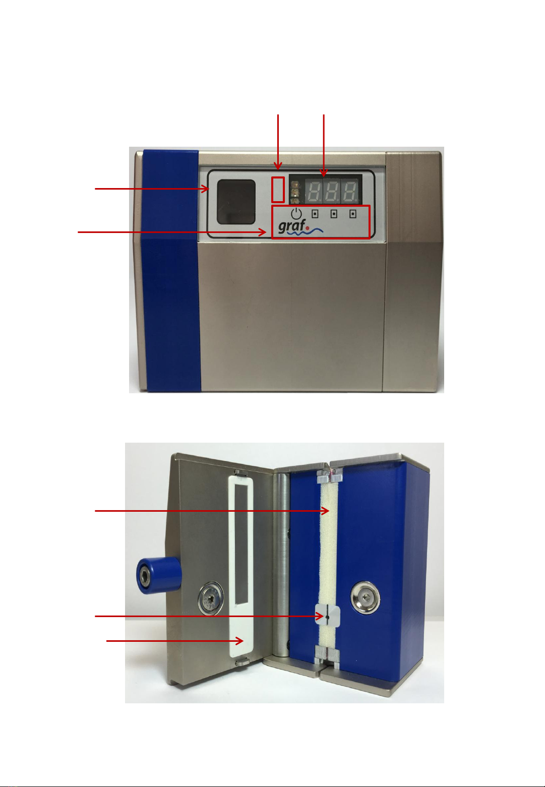
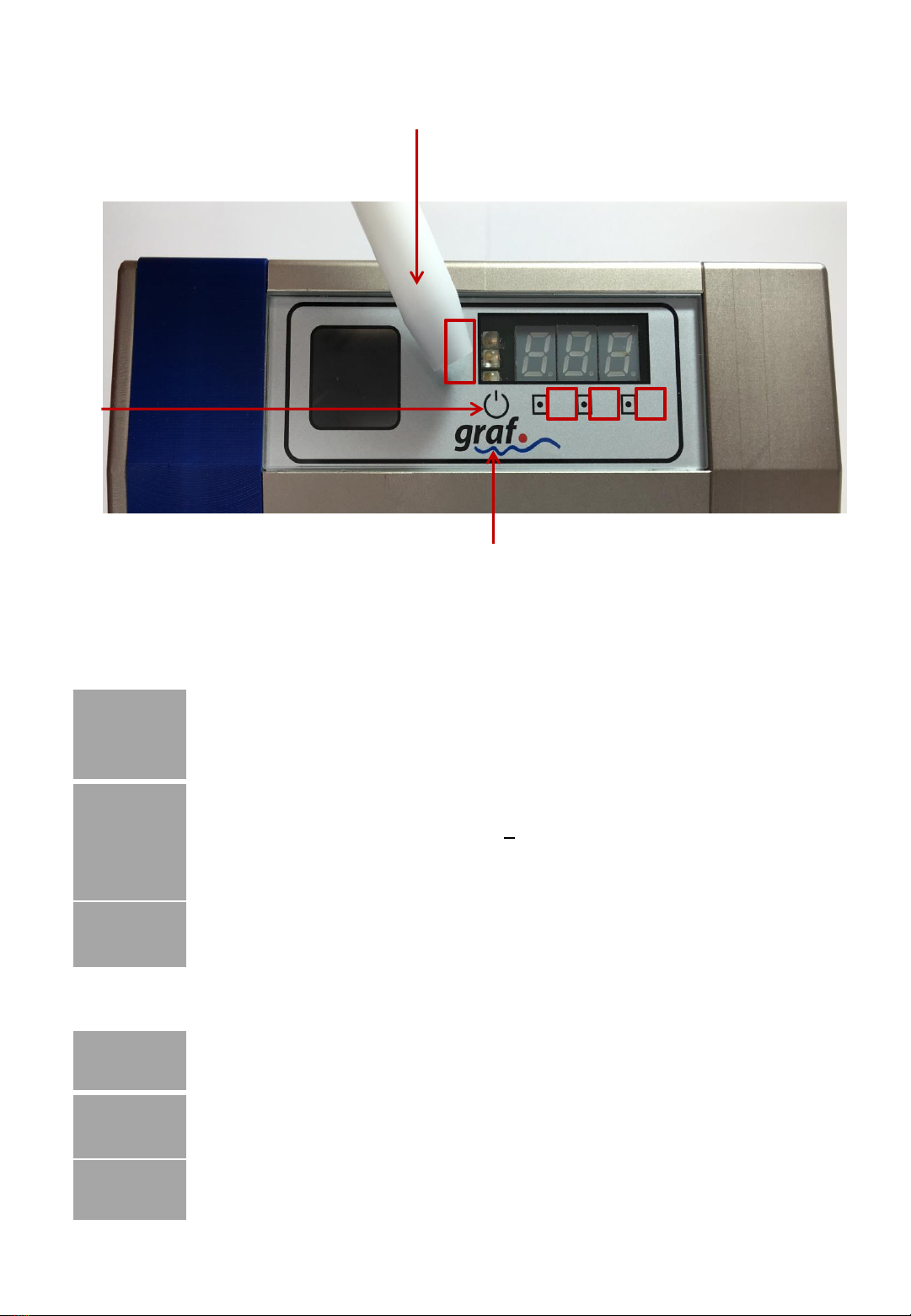
The output can now be adjusted using the keys 1, 2, 3. Each digit must be set separately.
With each press on the key, the corresponding number increases by 1.
Once the number 9 is passed, the unit return to zero.
 
 
%lub
1000%
activity
g
m
Nm
uptake
km
g
Setting
eff 














km
g
g
m
km
g
Setting 1
%10035
1000%5.3 









to set
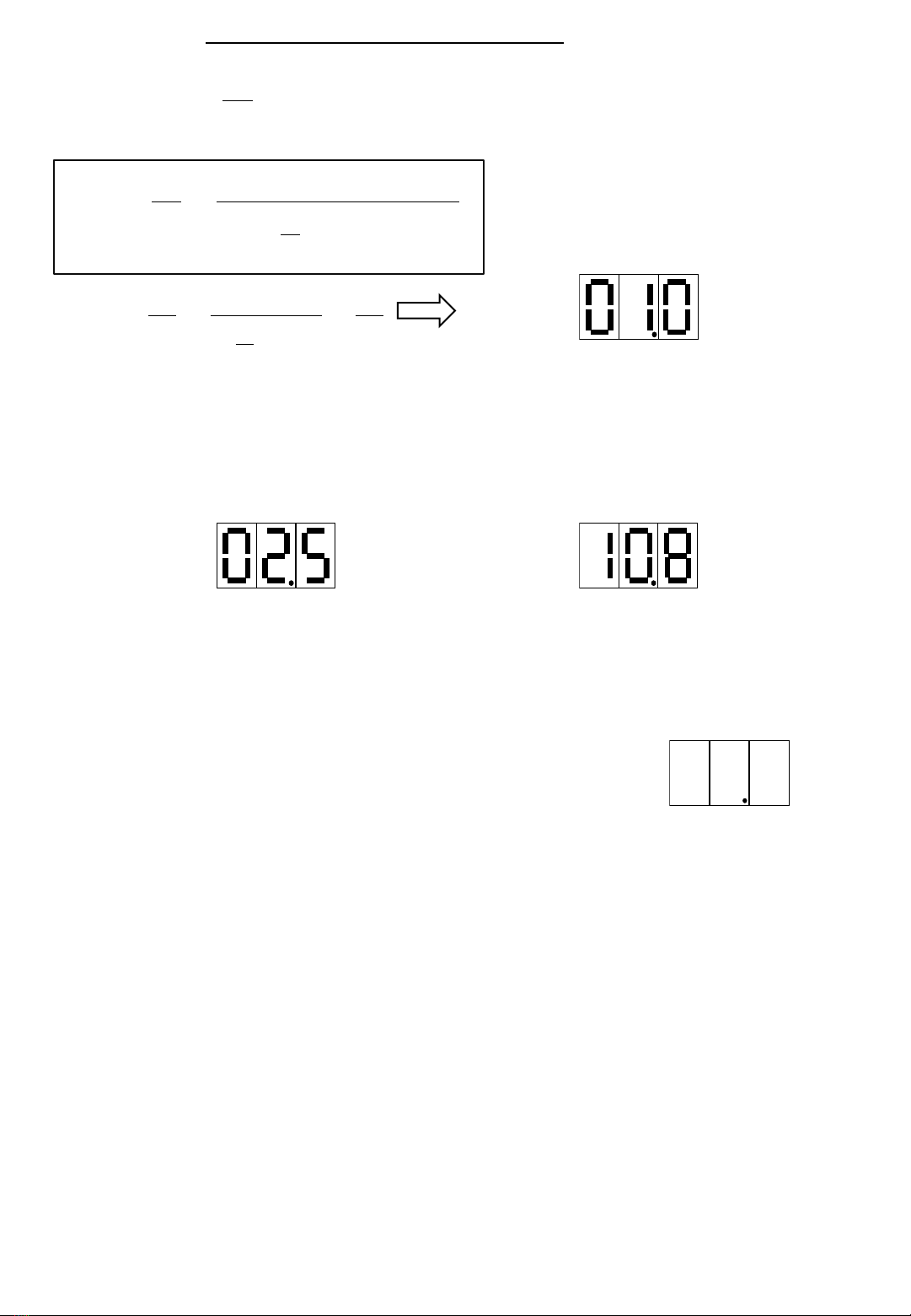
To change for example to
press the key 1once, the key 2eight times and the key 3three times.
Thus the output of 2.5 g/min has been changed to 10.8 g/min. This setting
remains the same until the next adjustment, even if the device is disconnected in
the meantime.
2.4 Turn on/off
With the I/O key the pump can be turned off. The display indicates:
The luminous decimal point of the second digit indicates that the pump is in off mode and will
not meter even if the winding machine is working.
By another press on the I/O key the pump is changed to on mode and the display shows the
value which was indicated before. The applicator is still hot.
2.5 Applicator Temperature
The current applicator temperature can be displayed by pressing MODE key at short term. In this
mode, the display shows degree sign (°) plus the current applicator temperature in degrees Celsius.
In order to exit applicator temperature display mode, press the MODE key once more.
This mode just displays the current applicator temperature.
The applicator temperature can be changed within a range of 20 to 80 degrees Celsius by modifying
the AtP Applicator Temperature Value in the configuration menu (see chapter 3.)
The standard setting is 60 degrees Celsius.
Instruction Manual GRAF SINGLE LUB 2 / Version 4.0 –05.2020 7
operating
mode
.
12.3
□I/O
t.60
Test run
time based
t.01 .. t.99
The time based test run is for feeding
lubricant with the Quantity set at the
Operating Mode for a determined count of
seconds. The Run starts by pressing I/O and
stops automatically when the time count-
down has reached 00. The Test Run can be
aborted at any time by pressing I/O.
Default-value: t.60
b.05° 60
□MODE
3. The configuration menu:
The device can be configured for different applications by using the MODE key. By pressing
this key repeatedly, several points of the menu are passed through which can be configured
as required.
ATTENTION: Only enter the configuration menu if changes are absolutely necessary. A
careless change of any parameter may lead to a malfunction of the device.
To enter the configuration menu, the MODE key must be pressed for 3 sec. After the last
menu item has been passed, the configuration menu is left automatically.
To leave the configuration menu prematurely, the I/O key must be pressed. Changed
parameters are automatically saved.
The configuration menu is passed through in the following order:
Applicator-
temperature *
□I/O □MODE
Acceleration
ramp **
□MODE [3sec.]
Stand-by
□MODE [3sec.]
Instruction Manual GRAF SINGLE LUB 2 / Version 4.0 –05.2020 8
□MODE
□I/O
r.50
Test run
turn based
r.01 .. r.99
The turn based test run is for feeding
lubricant with the Quantity set at the
Operating Mode for a determined
number of gear wheel turns. The Test run
starts by pressing I/O and stops
automatically when the turns you have
set are done. The Test Run can be aborted
at any time by pressing I/O.
Default-value: r.50
□MODE
□I/O
CAL.
170
Calibration
of feeding
quantity
Pump
feeding
quantity
calibration.
□MODE
050 ..250
This value determines the calibration setting
of the pump head. The value set describes
the feeding quantity of the pump in
milligram / turn. At this menu point the
display shos alterately CAL ad the
value set.
Default-value: nothing
ATTENTION:
Setting this to an improper value leads to an
incorrect feeding quantity.
□I/O
F.65
Fluid
motion
controller
sensitivity
determines
sensitivity
of the flow
motion
controller.
F.00 ..F.99
The reaction time of the flow motion
controller can be set using this value. The
higher the value, the faster the fluid motion
controller reacts. Normal reaction delay
should be within 50 ..70 seconds.
Default-value: F.65
□MODE
The red LED Clights up when the reaction
point has been reached. For test purposes,
the moment the parameter F is entered, the
flow motion sensor starts to detect if
lubricant is flowing through the pump. As
the motor is not running and no lubricant is
moving in this mode, the flow motion
sensor should show an error after approx. 1
minute. The red LED Cindicates the error.
With the value 00 the flow motion sensor is
completely switched off.
ATTENTION:
If this value is changed (especially by
increasing the sensitivity), the red LED C
might light up during normal operation. The
control unit is already factory –set at the
value of 65, which corresponds to the
required sensitivity of approximately 1
minute after interruption of output. When
the red LED Clights up, the winding
machine is stopped by the metering device
(only if connected).
Instruction Manual GRAF SINGLE LUB 2 / Version 4.0 –05.2020 9
□I/O
A.02
Applicator
setting
determines
type of
applicator
used.
□MODE
A.00..A.03
A.00: Cold applicator, no check of
temperature
A.01: Cold applicator with Clean-Start
(1.5 rotations).
A.02: Hot applicator
A.03: Hot applicator with automatic
temperature reduction at standstill
* Temperature display only active with
activated hot applicator
□I/O
Ad.0
automatic
temperature
reduction
determines
delay of
temperature
decrease
□MODE
Ad.0..Ad.6
If A.03 (hot applicator with automatic
temperature reduction at standstill) was
selected in the applicator setting, this menu
item is activated and the time delay of the
automatic temperature reduction when the
pump is at a standstill can be specified in 6
steps.
Ad.0: No delay (immediate temperature
reduction at standstill)
Ad.1: temperature reduction 10 seconds after
standstill
Ad.2: temperature reduction 30 seconds after
standstill
Ad.3: temperature reduction 1 minute after
standstill
Ad.4: temperature reduction 2 minutes after
standstill
Ad.5: temperature reduction 5 minutes after
standstill
Ad.6: temperature reduction 10 minutes after
standstill
□I/O
AtP.
°60
Applicator
temperature
determines
temperature
of applicator
□MODE
°20 ..°80
At this menu point the control temperature of
the Hot Applicator (if connected and with
A.02 / A.03 activated) is set. The temperature
value between 20 and 80 degrees is entered
in ° C. At this menu point the display shows
alterately AtP. ad the alue set of
temperature.
Default-value: °60
Instruction Manual GRAF SINGLE LUB 2 / Version 4.0 –05.2020 10