IOG 2216.01 Rev. 1 April 2010
2
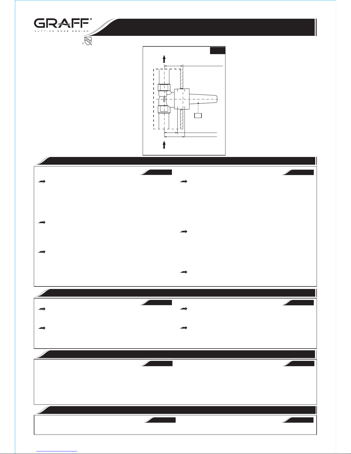
WALL MIN
WALL MAX
A
MIN.1-3/8"-MAX.2-1/8"
(MIN.35mm-MAX.54mm)
WATER SUPPLY
(from Thermostatic Mixing Valve)
SUMINISTRO DE AGUA
(del la Válvula Mezcladora Termostática)
TO RECEIVER
AL RECEPTOR
MIN. 1-3/8" (35mm)
MAX. 2-1/8" (54mm)
2.1
Prepare the recess in the wall for the valve body pipe Prepare la hendidura en la pared para el trabajo de la tuberia
work taking into account the maximum and minimum del cuerpo del mezclador considerando la profundidad máxima y
depth allowed. Place valve body with plaster guard (A) mínima permitida. Ponga el cuerpo de la válvula con protector del
into the wall recess. Recommended depth for valve body in yaso (A) en la hendidura de la pared. La profundidad recomendada
wall measured from center of valve outlet to finished wall para el cuerpo de válvula en la pared medida del centro del enchufe
surface is in the range 1-3/8” (35mm) - 2-1/8” (54mm). de la válvula a la superficie acabada de la pared esta en el intervalo
de 1-3/8” (35mm) - 2-1/8” (54mm).
Turn on the water supply lines to the valve, and check for
leaks. Run water through the mixing valve and all shower Abrir las líneas de suministro del agua para la válvula y
devices, and check the system for leakage. Use the controlar si no hay fugas. Dejar pasar el agua por la válvula
stop/volume control valve to control the water flow to the mezcladora y por todos los elementos de la ducha y controlar si no
shower outlets. hay fugas en el sistema. Usar la válvula de cierre/control de flujo
para controlar el flujo del agua por los cańos de la ducha. Cerrar el
agua. Terminar el acabado de la pared.
~
ESPANOL
ENGLISH
INSTALLATION INSTRUCTIONS INSTRUCCIONES DE INSTALACIÓN
See fig. 1.1, 2 1 Ver dis. 1.1 2 1. ,
Use correct piping use size accordingly from mixing valve to
stop volume control for optimal GPM perfomance.
Cap or plug outlets and test setup for leaks.
Turn off check valve stops on mixing valve.
Complete the finished wall. Flash all water lines.
: Remove cartridge if heating up the valve body
CAUTION
The water flow is opened using the lever or the cross handle. It is Para abrir la salida I de ajuste de temperatura sirve la palanca o la
opened fully by turning the lever (cross handle) in counterclockwise llave cruzados. Obtenemos la apertura completa girando la palanca (la
direction. llave cruzados) en la dirección opuesta al movimiento del reloj.
Lever or cross handle is used to open and regulate the flow of Para abrir la salida y ajustar el flujo del agua sirven la palanca o la
water. The flow is opened fully by rotating the lever or cross handle by llave cruzados . La apertura total la obtenemos girando la palanca o la
0
quarter-turn counterclockwise. The intensity of the water flow is llave cruzada 90 en contra del sentido de las manillas del rejol. La
0 0
regulated by positions between 0 ÷ 90 angle. regulación de la intensidad del flujo del agua sucede en las posiciones
0 0
entre 0 y 90 .
~
ESPANOL
ENGLISH
OPERATING INSTRUCTIONS DESCRIPCIÓN DEL FUNCIONAMIENTO
ENGLISH
~
ESPANOL
CARE AND MAINTENANCE CUIDADO Y MANTENIMIENTO
Your Graff valve is designed and engineered in accordance with the Su válvula de la Graff esta diseńado y se regido de acuerdo con los
highest quality and performance standards. Be sure not to damage the estándares de funcionamiento y calidad más altos. Este seguro no dańar las
finish during installation. Care should be given to the cleaning of this terminaciones del grifo durante la instalación. Cuide el producto
product. Although its finish is extremely durable, it can be damaged by manteniendolo siempre limpio. Aunque su acabado es extremadamente
harsh abrasives or polish. Never use abrasive cleaners, acids, durable, puede ser dańado por los abrasivos o pulientes ásperos. Nunca
solvents, etc. to clean any Graff product. To clean, simply wipe utilice limpiadores abrasivos, ácidos, solventes, el etc. para limpiar
gently with a damp cloth and blot dry with a soft towel. cualquier producto de la Graff. Para limpiar, simplemente use un
pańo húmedo y seque con una toalla suave.
~
ESPANOL
ENGLISH
WARRANTY GARANTÍA
Warranty conditions and warranty registration card are outlined on a Las condiciones de la garantía y la tarjeta del registro de la garantía se
separate sheet. encuentran en una pagina separada.
Use el de
de control de volumen a fin de obtener un
rendimiento óptimo de galones por minuto GPM.
correcto respectivamente, desde la tamańo cańeria
válvula mezcladora hasta
la válvula
Tape o conecte las solidas
y verifique que no existan fugas.Cierre los topes de las válvulas
de retención que se encuentran en la
válvula mezcladora.
Haga correr agua por todas las lineas de agua.
PRECAUTIÓN: Quite el cartucho si se produce el
calentamiento del cuerpo de la
válvula .
Installation Instructions Instrucciones de Instalación
3/4 STOP/VOLUME CONTROL VALVES
3/4 VÁLVULAS REGULADORAS DE CIERRE
This faucet complies with NSF61/9, ASME/ANSI A112.18.1
and CSA B 125 Standards.
Este grifo se encuentra conforme con losestandares de NSF61/9,
de ASME/ANSI A112.18.1 y de CSA B 125.