Gram Eco Plus U 70 Manual

765042411 Rev. 000
GRAM CO2storage refrigerator and
freezer cabinets
IC (integrated controller)
Danfoss controller (AKCC550A)
or
Carel Controller (MPXpro)
NC (No controller)
controller chosen and fitted by external technician
Installation- and service manual

Gram Commercial A/S
Aage Grams Vej 1
6500 Vojens
+45 73 20 12 00
www.gram-commercial.com

Contents
Intended use..............................................................................................................3
Location.....................................................................................................................4
General description ..................................................................................................6
Electrical connection................................................................................................7
How to connect the IC product to the CO2 system.................................................8
Connection diagrams for CO2 cabinets.................................................................12
How to operate the product ...................................................................................17
Operating the product (Danfoss Controller AKCC 550A)....................................17
Errors and alarms.......................................................................................................................19
User menu..................................................................................................................................20
Operating the product (Carel MPXpro controller)................................................21
Errors and alarms.......................................................................................................................27
Troubleshooting......................................................................................................28
Noise:.....................................................................................................................................28
Frosting inside compartment: .............................................................................................28
Poor cooling performance:..................................................................................................28
Some of the food is frozen:..................................................................................................29
Condensation around the door: ..........................................................................................29
Too high energy consumption: ...........................................................................................29
Defrosting................................................................................................................29
Defrost water...........................................................................................................30
Door closing mechanism .......................................................................................30
Power failure ...........................................................................................................30
Cleaning...................................................................................................................31
Door gaskets...........................................................................................................31
Long term storage ..................................................................................................31
Service.....................................................................................................................32
Wiring diagrams Danfoss AKCC 550A..................................................................33
Wiring diagrams Carel MPXpro .............................................................................40
Wiring diagrams –no controller............................................................................47
Piping diagrams......................................................................................................54
Declaration of incorporation of partly completed machinery.............................55
Appendix I (Danfoss AKCC550A settings)............................................................56
Appendix II (Carel MPXpro settings).....................................................................61

English
Thank you for choosing a Gram Commercial CO2product.
This manual is made to aid the following:
•The installer when integrating the Gram CO2product into a remote CO2installation.
•The service technician when servicing the cabinet.
BE AWARE:
Only technicians who have the right skill level regarding how to work on a CO2system and who have the
sufficient knowledge regarding the chosen controller, are allowed to carry out the installation regarding
connecting to the external system and adapting the controller parameters to fit the installation.
In order to make sure that the cabinet is connected and used as it is intended the below points must be
taken into consideration:
•Not to exceed PS on neither of the system sides (PS limits to be secured by the installer/safety
valves):
oPSLP-side = 60 bar
oPSHP-side = 90 bar
•Be aware of and instruct the end user only to use the cabinet as described under intended use.
•If the controller parameters are not adapted/adjusted correctly it can lead to severe damage to the
refrigeration system. This is the reason why sufficiently skilled personal is needed in order to be
able to correct/adapt the controller settings, making the cabinet and the external system run in
harmony. (All controller parameters should be checked by the installer prior to starting up the
product).
Intended use
This product is intended for professional use, meaning storing packed food stuff at a constant temperature.
The product may not be used to chill or freeze food stuff. For that purpose, use a blast-chiller or a blast-
freezer.
The product is only to be used for the purpose it was designed for (storing already chilled or frozen food
stuff, which is packed or in closed containers).
Any unintended use can result in the food stuff inside the product, not being kept at the right temperature.

Location
When receiving the product, check the packaging material for damage.
If any damage occurs at the packaging material, it should be considered if the product might have been
damaged too. If the damage is substantial, please contact your dealer.
The transport pallet can be removed by loosening the screws that fasten the pallet to the product (see the
below illustration).
This task requires at least 2 persons. The heaviest part of the product is at the top. Be
aware of this, when removing the transport pallet.
Because of the heavy weight of the product, the floor might be damaged or scratched
when moving the product.
Correct set up gives the most effective operation.
The product should be placed in a dry and adequately ventilated room.
To ensure efficient operation, it may not be placed in direct sunlight or against heat-
emitting surfaces. The product is designed to operate in an ambient temperature
between +16C and +40°C.
Avoid placement of the product in a chlorine/acid-containing environment (swimming
bath etc.) due to risk of corrosion.
The product and parts of the interior is equipped with a protecting film, which should be
removed before use.
Clean the product with a mild soap solution before use.

The set-up place must be level and horizontal.
It is very important to adjust the legs of the cabinet in order to make sure that the product stands
level and upright.
In order to avoid tensions in the cabinet construction, it is crucial to make sure that all legs make proper
contact with the floor, so that the stress to the cabinet is distributed evenly.
There must always be 20 cm of free space above the product, to allow for service.
The product should be placed as close as possible up against the wall.

General description
Front panel
Display
Door
Gasket
Air intake
Air distribution plate
Shelves for storage
Pedal door opener

Electrical connection
Read the text below thoroughly before electrical connection.
The product is intended for connection to alternating current. The connection voltage (V)
and frequency (Hz) is shown on the name plate in the cabinet (see Fig. 8). Do only
connect the product to the power supply which is stated on the product name plate. Only
the supplied or similar cord is to be used.
Never use an extension cord for this appliance!
If a wall socket is placed further away than the length of the supplied power cord, contact
an electrician to establish a wall socket within the range of the supplied power cord.
If the product is defective, it should be examined by the company which has connected
the product to the remote system. As a minimum, servicing and troubleshooting must be
carried out by a skilled service technician knowing the installed controller and
experienced in servicing a CO2cabinet.
Fig. 5 Fig. 8
Always disconnect the power if interruptions in power supply occur, and when electrical parts are
removed/put on, and before cleaning and maintenance of the product.
Do not re-connect the cabinet to the power supply until all covers have been re-installed in order to make
sure that no rotating, hot or live parts can be accessed/touched.
The product may not be installed/used outdoor.
All earthing requirements stipulated by the local electricity authorities must be observed. The plug and wall
socket should then give correct earthing. In case of any doubt, contact an electrician.
Make sure the product is switched off at the socket or that the kettle plug is
disconnected (Fig.5), before service is performed on electrical parts. It is not
sufficient to switch off the product at the controller.
If service is to be carried out on electrical parts the main power supply of the
cabinet must be disconnect. This can be done by pulling the plug out of the
wall socket or by pulling the kettle plug on the rear or the left side of the main
control box (depending on model). It is not enough to turn off the power supply
on the 2-pole main switch, as there will still be power on the appliance inlet
inside the control box.
Type
REF
PO No
S/N
Input: V Hz W A
Defrost: W
Refrigerant: g
Climate cla ss:
Isolation class:
Foam propellant Cyclopentane
Permissible operati on over-pressure: Suction side: 10 bar
Discharge side: 25 bar
Gram Com mercial A/S
Aage Gr ams Vej 1, 6500 Vojens
Denmar k CVR nr. 12 00 66 32
Type
REF
PO No
S/N
Input: V Hz W A
Defrost: W
Refrigerant: g
Climate cla ss:
Isolation class:
Foam propellant Cyclopentane
Permissible operati on over-pressure: Suctions ide: 10 bar
Discharge side: 25 bar
Gram Com mercial A/S
Aage Gr ams Vej 1, 6500 Vojens
Denmar k CVR nr. 12 00 66 32

How to connect the IC product to the CO2 system
These products have been designed, constructed and built to minimize the time which the installer must use
before and after connecting them to the remote CO2 –installation. On cabinets referred to as IC, with a built-
in controller (either Danfoss AKCC 550A or Carel MPXpro), every electrical component is already connected
to the controller and the controller is configured accordingly. All controller parameter setups have been made
in cooperation with the two controller manufacturers (Danfoss and Carel), in order to make sure that the
cabinet will run when connected. There might of cause be settings which need to be changed/adapted in
order to optimize performance according to the remote system.
A few examples:
Solid door cabinets are delivered with auniversal set pointrange +12to -25°C, whichmeans that thecabinets
can be installed as a fridge or as a freezer. The reason for this is that all solid door cabinets are delivered as
a freezer configuration, including electrical defrost heater, door frame heater etc. for maximum flexibility
during installation.
If the cabinet is to run as a refrigerator it will most likely be connected to a remote system which will run a
suction pressure no lower than -10°C (often even higher). in this case it is recommendable to raise the
minimum allowed set point to approx. +2°C. which does mean that the adjustment range will be +2 to +12°C.
If the same universal cabinet is to run as a freezer, connected to a remote freeze system, the range should
be narrowed to e.g. -10 to -22°C or similar, to suite the settings of the remote system.
The difference between controller minimum setpoint temperature and the minimum suction pressure should
never be less than 7K.
IMPORTANT!
People installing these products, should have the right skill level.
This does relate to all aspects. (physical installation as well as adapting the controller settings of the
chosen controller, in order to avoid problems or potentially dangerous situations)
Always make sure that the cabinet is properly leveled when positioned on the installation location.
This should be done prior to connecting the pipe work to the remote CO2 system
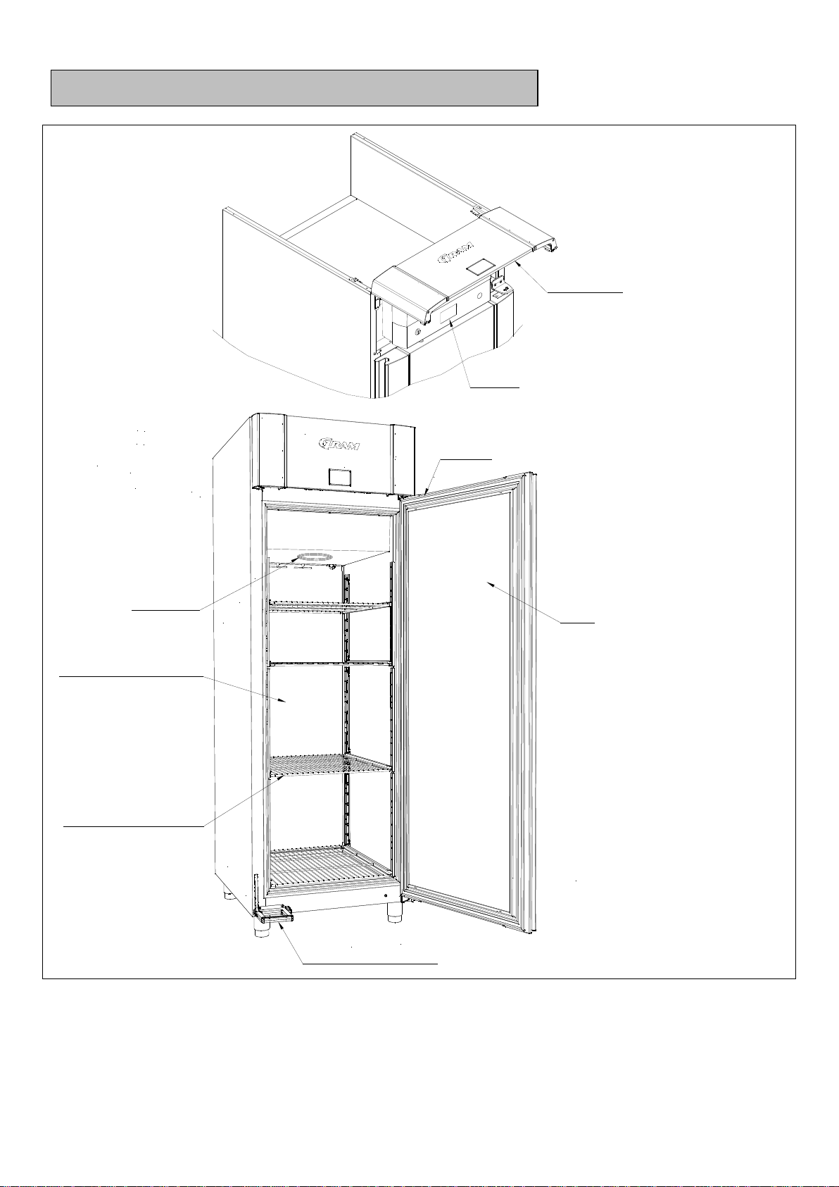
Commonly used parts on all IC upright storage cabinets:
The refrigeration system on the cabinet consists of:
•An evaporator coil (PS = 60bar)
•A Danfoss AKVP 10-1 electronic expansion valve with coil and the cobber pipes used to connect the
system.
•3 temperature sensors Danfoss PT1000 marked according to Danfoss standard - room sensor (S3)
and super-heat sensors (S2) are AKS11, Evaporator/defrost sensor (S5) is AKS12.
•A Carel suction line pressure transmitter (0-5V radiometric type (0-45 bargauge) female connection =
¼” SAE) Only connected electrically –To be fitted on the suction line by the installer.
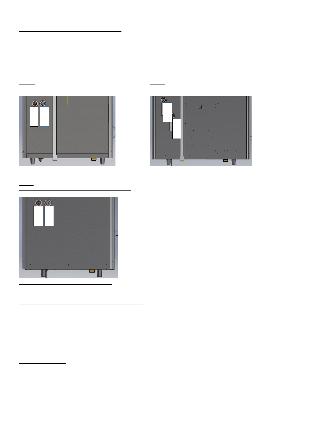
After assembly, the system is pressure tested with 1,43 x PS (in the factory).
Recommended installation of the pressure transmitter is horizontally in the suction line (Done by the installer)
All parts are assembled and fitted on the cabinet, so that the installer does not need to access the evaporator
compartment or the controller box, during installation.
Exception: it will be necessary to open the controller box:
•in order to connect the cabinet controller to an external surveillance system. (Done by the installer)
•if e.g. drain line heater needs to be disconnected, when connection to an external drain solution.

On PLUS, TWIN and EURO products the pipe ends for connecting to a remote system are in the top
compartment (shown on the below fig. 1 –3). Both pipes are clearly marked in order to avoid connecting the
cabinet wrongly. Both connection pipes coming out of the cabinet are 3/8”.
The pressure transmitter, which must be connected to the suction line, by the installer, is lying in the top
compartment. This transmitter is connected to a detachable connection wire, which is connected inside the
controller box. (length approx. 1,5 meter out of the controller box)
Fig. 1 Fig. 2
Top view showing pipe connections on ECO PLUS cabinets Top view showing pipe connections on ECO TWIN cabinets
BACK OF CABINET BACK OF CABINET
Fig. 3
Top view showing pipe connections on ECO EURO cabinets
BACK OF CABINET
Drain water on PLUS, TWIN and EURO products
These cabinets are delivered with a re-evaporation tray with an electrical heater (100 Watt), positioned
underneath the cabinet. The heaater is controlled by the main controller. This is done so that the cabinets
can be used where there is no external drain available. If there is an external drain available or there is a
possibility of connecting the cabinet drain outlet to an external drain pump, one of these solutions is always
recommendable in order to save energy. If the cabinet drain water outlet can be connected to one of the two
alternative solutions, the tray and the 100 Watt heater should be removed prior to installing the cabinet. As a
minimum the heater must be disconnected in the controller box.
On MIDI products the pipe ends for connecting to a remote system are on the rear of the cabinet (shown on
the below fig. 4). Both pipes are clearly marked in order to avoid connecting the cabinet wrongly. Both
connection pipes coming out of the cabinet are 3/8”.
The pressure transmitter, which must be connected to the suction line, by the installer, is lying in the bottom
compartment. This transmitter is connected to a detachable connection wire, which is connected inside the
controller box. (length approx. 2,5 meter out of the controller box).
Inlet
Outlet
Inlet
Outlet
Outlet
Inlet

Fig. 4
Rear view showing pipe connections on ECO MIDI cabinets
Drain water on MIDI products
These cabinets are delivered with a re-evaporation tray with an electrical heater (60 Watt) and a float switch
which does control the operation of the heater related to water level inside the tray. This system is positioned
inside the bottom compartment of the cabinet on the right side seen from the front. This is done so that the
cabinets can be used where there is no external drain available. If there is an external drain available or there
is a possibility of connecting the cabinet drain outlet to an external drain pump, one of these solutions is
always recommendable in order to save energy. If the cabinet drain water outlet is connected to one of the
two alternative solutions, the complete tray including 60 Watt heater, float switch, junction box, connection
wire and brackes, should be removed prior to installing the cabinet. As a minimum the re-evporation system
must be disconnected in the controller box.
How to connect the NC product to the CO2 system
These products have been designed, constructed and built to minimize the time which the installer must use
before and after connecting them to the remote CO2 –installation. On cabinets without controller known as
NC, every electrical component is already fitted and connected to a connection plinth inside the control box.
Inside the control box a DIN rail is fitted in order to ease mounting of any controller.
When installing the controller of your choice, you should take into consideration, that solid door cabinets are
delivered equipped with components which makes the product capable of running with a temperature set
point range between +12 and -25°C. This means that the cabinets can be built as a fridge or as a freezer.
The reason for this is the desire of leaving maximum flexibility to the installer/refrigeration company when
building the product needed.
This fact does also mean that the following heaters are included:
Electrical defrost heater, drain line heater, re-evaporation heater and door frame heater. These heaters are
not necessarily to be used if a refrigerator is to be configured.
If the cabinet is to run as a refrigerator it will most likely be connected to a remote system which will run a
suction pressure no lower than -10°C. in this case it is recommendable to raise the minimum allowed set
point to no lower than +2°C. which does mean that the adjustment range will be +2 to +12°C.
The difference between controller minimum setpoint temperature and the minimum suction pressure should
never be less than 7K.
If the NC cabinet is to run as a freezer the set point temperature range should be narrowed according to the
performance of the freezer system to which it is connected. E.g. -10 to -22°C or similar.
Outlet
Inlet

IMPORTANT!
People installing these products, should have the right skill level.
This does relate to all aspects. (physical installation as well as adapting the controller settings of the
chosen controller, in order to avoid problems or potentially dangerous situations)
Always make sure that the cabinet is properly leveled when positioned on the installation location.
This should be done prior to connecting the pipe work to the remote CO2 system.
Commonly used parts on all NC upright storage cabinets:
The refrigeration system on the cabinet consists of the following:
•An evaporator coil (PS = 60bar)
•A Danfoss AKVP 10-1 electronic expansion valve with coil and the cobber pipes used to connect the
system.
•3 temperature sensors Danfoss PT1000sensors marked according to Danfoss standardroom sensor
(S3) and super-heat sensors (S2) are AKS11, Evaporator/defrost sensor is AKS12 (S5).
After assembly, the complete system is pressure tested with 1,43 x PS (in the factory).
All parts are assembled and fitted on the cabinet, so that the installer does not need to access the evaporator
compartment, during installation, unless the sensors need to be changed due to the fact that the controller
chosen, is not suitable for PT1000 sensors.
On PLUS, TWIN and EURO products the pipe ends for connecting to a remote system are in the top
compartment (shown on the below fig. 1 –3). Both pipes are clearly marked in order to avoid connecting the
cabinet wrongly. Both connection pipes coming out of the cabinet are 3/8”.
Fig. 1 Fig. 2
Top view showing pipe connections on ECO PLUS cabinets Top view showing pipe connections on ECO TWIN cabinets
BACK OF CABINET BACK OF CABINET
Fig. 3
Top view showing pipe connections on ECO EURO cabinets
BACK OF CABINET
Drain water on PLUS, TWIN and EURO products
Inlet
Outlet
Inlet
Outlet
Outlet
Inlet

These cabinets are delivered with a re-evaporation tray with an electrical heater inside (100 Watt), positioned
underneath the cabinet. The heater should be controlled by the main controller. This re- evaporation system
is installed as a standard, so that the cabinets can be used where there is no external drain available.
If there is an external drain available or there is a possibility of connecting the cabinet drain outlet to an
external drain pump, one of these solutions is always recommendable, in order to save energy and reduce
maintenance costs. If the cabinet drain water outlet can be connected to one of the two alternative solutions,
the tray and the 100 Watt heater should be removed prior to installing the cabinet. As a minimum the heater
must not be connected to power in the controller box.
On MIDI products the pipe ends for connecting to a remote system are on the rear of the cabinet (shown on
the below fig. 4). Both pipes are clearly marked in order to avoid connecting the cabinet wrongly. Both
connection pipes coming out of the cabinet are 3/8”.
Fig. 4
Rear view showing pipe connections on ECO MIDI cabinets
Drain water on MIDI products
These cabinets are delivered with a re-evaporation tray with an electrical heater (60 Watt) and a float switch
which does control the operation of the heater related to water level inside the tray. This system is positioned
inside the bottom compartment of the cabinet on the right side seen from the front. This is done so that the
cabinets can be used where there is no external drain available.
If there is an external drain available or there is a possibility of connecting the cabinet drain outlet to an
external drain pump, one of these solutions is always recommendable in order to save energy. If the cabinet
drain water outlet is connected to one of the two alternative solutions, the complete tray including 60 Watt
heater, float switch, junction box, connection wire and brackes, should be removed prior to installing the
cabinet. As a minimum the re-evaporation system must must not be connected to power in the controller box.
Connection diagrams for CO2 cabinets
In order to ease the planning/positioning of pipe work, external drain work and electrical installations related
to installing the Gram CO2 products, the drawings on the next four pages have been created.
Outlet
Inlet

PLUS

TWIN

EURO

MIDI

How to operate the product
The end user is not allowed to access very many parameters in the controller. This fact does however
demand more of the installer in terms of adapting the controller settings to meet the needs of the end user,
as well as adapting the controller settings to operate in harmony with the remote refrigeration installation.
In terms of knowing the Gram factory settings which have been made to the controller installed, the
following appendixes have been added at the end of this document (see table of contents)
•Appendix I related to Gram settings of the Danfoss AKCC-550A controller.
•Appendix II related to Gram settings of the Carel MPX-pro controller.
These appendixes show all the settings which have been made as a default, in order to make sure the
product will run as desired when delivered. The hardware configuration of the cabinet does however allow
the cabinet to run as:
•A standard U-cabinets (solid door) setpoint +12 to -25°C (default) To be adapted to customer needs
and system limitations.
•As a glass door refrigerator KG-cabinet +12 to +2°C (default not to be changed for lower settings)
•As a Glass door freezer (only MIDI) -5 to -22°C. (Default)
IMPORTANT:
Know that refrigerator cabinets with glass door (KG), cannot be changed to run as freezers, due to the fact
that the refrigerator glass doors, does not include a heating element needed on the freezer in order to avoid
condensation.
It is very important always to check all the parameters in the controller, in order to verify the settings in
terms of correctness and suitability related to demands and refrigeration installation. The settings which are
made from the factory are not necessarily suitable for the system which the cabinet is to be integrated into.
Operating the product (Danfoss Controller AKCC 550A)
Starting up:
Plug in the appliance.
Make sure that the 2 - pole main switch is turned on.
The display part is placed behind the top panel and can be accessed by opening the top panel.
Display explanation:
The above shown display part has a three-digit read-out.
On the left side of the read out, three LEDs are placed. These three LEDs have the following purpose.
= Cooling on (when this LED is lid, the cooling is on)
= Defrost on (when this LED is lid, a defrost cycle is ongoing)

= Inside fan running (when this LED is lid, the internal fan is on)
If all three LEDs are flashing, this is an indication for an ongoing alarm or error.
The 3 buttons placed on the right side of the display read-out, are used to access and adjust different
parameters.
Buttons:
The upper button:
•if pushed shortly during normal operation the controller will cancel and display any error(s) occurring.
If more than one alarm does occur, use the uppermost or lowermost button to scan the different
alarms.
•if pushed and kept pushed during normal operation until the display shows r01 the main parameters
of the controller are accessed. This is only used by the end-user when switching the controller on
and off.
•If pushed being in a set menu (either change of a setting or moving from one parameter to another
the value will be increased)
The centre button: (Adjusting the cabinet temperature set point)
•if pushed and kept pushed during normal operation until the display starts flashing, the cabinet
temperature set-point can be adjusted using the upper and lower button.
•If pushed after changing a value the controller does save the new value and return to the previous
level.
The lower button:
•if pushed shortly during normal operation the controller will display the actual temperature of the
evaporator probe.
•if pushed and kept pushed for more than 4 seconds, during normal operation, an ongoing defrost
cycle will be cancelled or a manual defrost cycle will be started.
•If pushed being in a set menu (either change of a setting or moving from one parameter to another
the value will be decreased)
The temperature alarm limits desired by the end user, must be set in the controller by the
installer. Please be aware of this in order to leave a good impression with the customer.
The parameters in question are e.g.:
A13 and A14
As an end-user it should only be possible to make the following adjustments:
•Adjusting the cabinet temperature set point (as explained above)
•Turning the cabinet controller on/off
•Switching the internal light (Only on MIDI KG/FG products)
Turning the cabinet on/off
As default setting the cabinet controller is delivered turned off.
This means that the display will show oFF, when power supply is connected. Please also check that
the main switch, placed on the control box is turned on.
The following is done in order turn the controller on. The same approach is used when turning the
controller off (Setting r12 to 0).
•Push the upper button and keep it pushed during normal operation until the display does show r01.

•Push the upper or the lower button until r12 is displayed.
•Push the centre button.
•Push the lower or the upper button in order to switch between the settings 0 and 1 (-1 is only for
service).
oSetting 0 means the cabinet is OFF.
oSetting 1 means the cabinet is ON.
•Confirm the new setting by pushing the centre button.
In order to skip the r01 parameter, the controller does only need to be left untouched for approx. 30
seconds. This will make the controller fall back to the normal operation mode, meaning that the
cabinet will either be in OFF –mode or be running.
Cabinet light
On all cabinets, besides the MIDI glass door cabinets with internal light, the cabinet light is placed on the
cabinet outside, above the door. This light is operated by the main controller which means that the way it
works cannot be changed.
When the cabinet door is opened the light above the door is turned on. When closing the door again, the
cabinet light above the door will remain on for two minutes. These two minutes are a main function in the
Danfoss controller which cannot be adjusted. Two minutes after closing the door the light will switch off.
Switching the internal light (Only on MIDI Glass door products - KG/FG)
On a Midi glass door cabinet, the cabinet LED lights are placed on the left and the right front wall rails
inside the cabinet storage room. The light can be operated in two different ways:
1. When the cabinet door is opened the internal light is turned on. When closing the door again, the
cabinet internal light will remain on for two minutes. These two minutes are a main function in the
Danfoss controller which cannot be adjusted. Two minutes after closing the door the light will switch
off.
2. By switching the light toggle switch in the left front of the top control box, placed behind the top
panel, to the position showing a light bulb, the internal light will be turned on constantly (not affected
by opening and closing the door).
Errors and alarms
This manual suits for next models
8
Table of contents
Other Gram Refrigerator manuals

Gram
Gram KF 32295-63 N User manual

Gram
Gram KS 3215-93/1 User manual

Gram
Gram KC 371185 User manual

Gram
Gram KF 471552 v/1 User manual

Gram
Gram KF 3135-91/1 User manual

Gram
Gram KF3135-90 User manual

Gram
Gram KF 3205-90 User manual

Gram
Gram Baker SF 1500 G Service manual

Gram
Gram KSI 200 User manual

Gram
Gram ECO User manual

Gram
Gram KPS 60 User manual

Gram
Gram KF 3295-93N User manual

Gram
Gram Type FS User manual

Gram
Gram KF 3295-93 X User manual

Gram
Gram KFI 401754 N User manual

Gram
Gram KFI 401754 N/1 User manual

Gram
Gram KS 290-01 User manual

Gram
Gram ECO PLUS User manual

Gram
Gram KF 3245-93 User manual

Gram
Gram Type K User manual