Graphic Whizard PT 331SCC User manual

1
1/13/2021
Table of Contents
Chapter 1 Introduction .................................................................................................................................................3
1.1 Preface................................................................................................................................................................3
1.2 Safety ..................................................................................................................................................................3
Power Supply ........................................................................................................................................................3
Chapter 2 Specifications ...............................................................................................................................................4
Chapter 3 Main Parts & Assemblies .............................................................................................................................5
Chapter 4 Installation ...................................................................................................................................................7
4.1 Unboxing and Inspection....................................................................................................................................7
4.2 Machine Assembly..............................................................................................................................................8
4.2.1 Outfeed Tray and Card Catcher ...................................................................................................................8
4.2.2 Extension Table Installation.........................................................................................................................8
4.2.3 Power Socket and Switch.............................................................................................................................8
Chapter 5 Operation.....................................................................................................................................................9
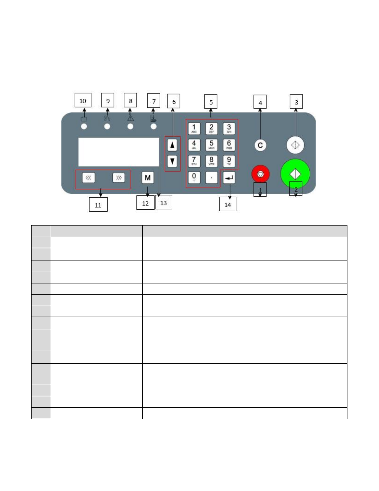
5.1 Key Panel Introduction .......................................................................................................................................9
5.2 Quick Start ........................................................................................................................................................10
5.3 Screen ...............................................................................................................................................................10
5.3.1 Welcome Screen........................................................................................................................................10
5.3.2 Ready Screen..............................................................................................................................................10
5.3.3 Mode Introduction.....................................................................................................................................12
5.3.4 Smart Input Mode......................................................................................................................................16
5.3.5 Job Layout Creation ...................................................................................................................................18
5.3.6 Parameters.................................................................................................................................................18
5.3.7 Job Layout Parameters ..............................................................................................................................19
5.3.8 How to Create a Register Mark..................................................................................................................23
5.3.9 How to use a Register Mark.......................................................................................................................24
5.3.10 Using the Cut Mark Registration..............................................................................................................24
5.4 Hardware Setting..............................................................................................................................................25
5.4.1 Side Guide Setting......................................................................................................................................25
5.4.2 Positioning Slitters .....................................................................................................................................25
5.4.3 Skew Adjustment.......................................................................................................................................26
5.4.4 Outfeed Tray Setting..................................................................................................................................27

2
5.5 Slitters Setting...................................................................................................................................................28
5.5.1 Compensation for Image Shift Left/Right..................................................................................................29
5.5.2 Side Trimming............................................................................................................................................30
5.5.3 Paper Deflectors ........................................................................................................................................31
5.5.4 Set Crease Data..........................................................................................................................................31
5.6 Side-Sheet Trimming.........................................................................................................................................31
5.6.1 Slitter Placement........................................................................................................................................31
5.6.2 Set Cut Data ...............................................................................................................................................32
5.7 Slide-in Tools.....................................................................................................................................................32
5.7.1 Change Perforate Crash Pad......................................................................................................................33
5.7.2 Crease Depth Adjustment..........................................................................................................................34
5.8 Slitter Removal and Replacement ....................................................................................................................35
5.9 Slitter Blade Removal Procedure......................................................................................................................37
Chapter 6 Trouble Shooting........................................................................................................................................39
6.1 Error and Warning Codes..................................................................................................................................39
6.1.1 Warning......................................................................................................................................................39
6.1.2 Error...........................................................................................................................................................41
6.2 Image Compensation........................................................................................................................................42
Chapter 7 Maintenance..............................................................................................................................................43

3
Chapter 1 Introduction
1.1 Preface
This manual only applies to the PT 331SCC. This manual contains information regarding machine safety and use.
Please keep the manual on hand for easy access when required. Do not operate the Graphic Whizard PT 331SCC
until you read and understand the instructions in this manual. Any questions regarding this machine, please contact
Graphic Whizard.
Graphic Whizard pursues a policy of continuing improvement in design and performance of the product.
Therefore, the product design and specifications are subject to change without notice.
1.2 Safety
•Please shut down and disconnect the power to the machine before performing maintenance. Make note
of connections before disconnecting. Ensure all cables are properly secured to the board.
•Read this entire manual before running the machine.
•Ensure all accessories are installed properly before running the machine.
•Ensure the power input and ground are correct before powering on the PT 331SCC. This machine runs on
110 volts
•Ensure all safety covers are in place. Do not run the PT 331SCC without the covers installed. The top cover
has an interlock switch that will stop the machine if open or removed.
•For personal safety, disconnect power before cleaning the interior of the machine.
•The blade edges are very sharp. Use caution whenever accessing the interior of the unit.
•Disconnect the power cord if the machine will not be used for an extended period.
•Install the PT 331SCC on a level surface.
•Never operate the unit with wet hands or connect or disconnect the power cord when wet or when
standing in water.
•Keep hair and clothing away from the unit.
•Keep hands clear of the unit when operating. Keep liquids away from the PT 331SCC.
•Do not place any heavy material on the machine.
•To avoid risk of shock or fire, keep metal and flammable materials out of the machine. If the unit is
exposed to shock or fire and if it is safe to do so, power off and unplug the unit then call a service
technician. Do not power on the unit without consulting a service technician.
•If the machine overheats or if you detect an odor or see smoke, immediately shut down the unit and
contact your local service technician.
Power Supply
•The AC input voltage frequency is AC110/50-60Hz. Please use a power cord rated for 10A or higher.
•If the voltage or frequency is not within range, the machine may fail to function.
•Do not remove the power cord while machine is in use. Power down the PT 331SCC before disconnecting
the power cord.
•Ensure the unit is connected to a properly grounded outlet before powering on.

4
Chapter 2 Specifications
Item
Parameter
Package Dimensions
Length*Width*Height (inch) (mm)
52.36” x 22.44” x 38.5”
(1330 x 570 x 980mm)
Machine Dimensions
Length*Width*Height (inch) (mm)
26.38” x 24.80” x 45.28”
(670 x 630 x 1150mm)
Net Weight
KG / LBS
100kg / 220 lbs.
Package Weight
KG / LBS
116kg / 255 lbs.
Power
Input
AC110V, 50/60Hz, 150W
Output Size
Max (W*L) (inch) (mm)
12.52”x 25.50”(318 × 640mm)
Min (W*L) (inch) (mm)
2.17” x 1.89”(55 × 48mm)
Infeed Size
Max (W*L) (inch) (mm)
13” x 25.5” (297 × 650mm)
Min (W*L) (inch) (mm)
6.5” x 8.27” (210 × 210mm)
Thickness
0.006” - 0.014”
150g - 350gsm / 0.15 - 0.35mm
Paper Waviness
0.118” (±3mm)
Max Qty for Cutter per Sheet
32
Accuracy for Cutting
±0.008” - 0.016” (0.2 - 0.4mm)
First Cut
0.126” - 0.591” (3.2 - 15mm)
Last Cut
0.197”- 0.591” (5 - 15mm)
Gutter Cut
0.118”- 0.591” (3 - 15mm)
Slit
Slitters
4
Side Trim
3.2mm-10mm (0.126” – 0.375”)
15mm or greater
Gutter Slit
0.375”(10mm)
Accuracy for Slitting
±0.0118”(0.3mm)
Crease
Max Qty for Crease per Sheet
32
Crease Depth Adjustment
Infinite Manual Adjustment
Crease Direction
Both
Crease Die Spec.
1.0mm
Perforator
Perforate Die Spec.
12 TPI
Speed
A4 trimming 4 sides, crease in middle
20 sheets/min
Feeding
Middle Infeed
Hand Feed
Custom Memory Storage
20
Register Mark
Y Direction only
Image Compensation
Y Direction Compensation Only
Environment
Temperature
10°C to 35°C / 50°F to 95°F
Humidity
30% to 70%

5
Chapter 3 Main Parts & Assemblies
No.
Item
Description
1
Waste Bin
Catches the cut waste
2
Out Feed Tray
For longer cut crease jobs
3
Card Collector
Collect finished business cards
4
Top Cover
Protection
5
Keypad
Machine programming and operation
6
Feed Table
Paper input
7
Machine Body
Working body of the PT331SCC
8
Side Cover
Access panel for changing the crease die or
perforate die
9
Tools Storage
Holder for crease and perf tools
10
Stand
Holds the waste bin and tool accessories

6
No.
Description
Remark
1
Crease Depth Adjust Screw
Turn clockwise to lighten the depth, counterclockwise to deepen the
depth.
2
Cross Cutter
Cut paper in cross direction
3
Lag Wheel Set
Adjust the roller pressure
4
Slitter #1
Slit the side edge of paper
5
Slitter #2
Slit with fixed gutter, gutter is 8mm or 3/8”
6
Slitter #3
Slit with fixed gutter, gutter is 8mm or 3/8”
7
Slitter #4
Slit the other side edge of paper
8
Manual Side to Side
Adjustment
Adjust slitter side to side positions

7
Chapter 4 Installation
4.1 Unboxing and Inspection
•Check for any obvious damage as soon as the item is received.
•If the package is damaged, perform a visual inspection before uncrating the PT331. Document any marks
or dents with pictures.
•If there is no visible damage, open the package and use the packing checklist to check for any missing or
broken parts. If there is any visible damage or parts that are missing, please take pictures and notify
Graphic Whizard immediately.

8
4.2 Machine Assembly
4.2.1 Outfeed Tray and Card Catcher
The card catcher is designed to sit just behind the exit rollers, allowing the cards to fall freely from the machine.
Use the deflectors to help guide the cut stock.
4.2.2 Extension Table Installation
Attach the feed extension table to the PT 331SCC by loosening the three hex screws and slipping the tray over the
screws. Ensure the tray remains level when tightening the screws.
4.2.3 Power Socket and Switch
AC input, voltage/frequency is 110V/50-60Hz. Note: For machine and operator safety, there is a fuse in the power
inlet. If the machine does not power on when connected to a functioning 110V power outlet, check the fuse.

9
Chapter 5 Operation
5.1 Key Panel Introduction
The control panel consists of keys and screen, as per following picture:
No.
Key
Description
1
Stop
Stops the current job.
2
Start
Runs the current job.
3
Test
Runs a single sheet for testing purposes.
4
Clear
Clears the data or error.
5
Number Pad
Used to input job data.
6
Scroll
Advance to the next option.
7
Indicator- No Paper
No paper or infeed Jam error indicator.
8
Indicator- Motor Error
E-1 CR Motor Error. Indicates a crease motor lock error.
9
Indicator- Paper Jammed
C-2 Jam at in feed error or C-3 Jam at out feed error (see display). Paper
jam error.
10
Indicator- Safety Cover
C-1 CR cover open. Safety cover is open.
11
Forward/Reverse
Increase/Decrease
Used to clear jams. Whenever possible, move the paper towards the
outfeed rollers.
12
Mode
Change the modes
13
Screen
Display information.
14
Enter
Press enter to confirm changes.

10
5.2 Quick Start
1. Power on the PT331SCC.
2. Select a preset template option from Mode or create a new template by following the procedure detailed
in 5.3.3
3. Add paper and adjust the side guides to secure the stock. The guides move towards the center of the
machine (center justified).
4. Ensure the output tray is installed. If cutting business cards, add the card catcher and deflectors.
5. Run a test cut by pressing the test key. Check alignment and skew. If the paper is skewed, adjust the side
guides referred to in section 5.4.2.
6. If the finished pieces are not OK, use the compensation function to make the appropriate adjustments.
7. Once the cut and adjustments are set, press Start to run the job. You can input the quantity you would
like to cut by entering the number and pressing the Enter key before pressing Start. If you are not using
the Batch function, press Stop once the desired number of sheets have been cut.
5.3 Screen
5.3.1 Welcome Screen
When you first power on the PT 331SCC, the screen will show a welcome message, then go to the Ready Screen.
5.3.2 Ready Screen
From the ready screen, press the Page down key to scroll through the various options. There are five options
from the ready screen:
•Cut data
•Crease data
•Total sheets
•Crease and cut quantity
•Software version
Main Screen Ready Status

11
Cut Data Screen
The data cut screen shows the currently programmed cuts. If no cuts have been programmed, the values will
display as 0. The maximum number of programmable cuts is 32. To page through the programmed cuts, press the
Up or Down arrows on the keypad (page up / page down).
Crease Data Screen
Like the cut data screen, the crease data screen displays the programmed creases. A total of 32 creases can be
programmed. To view the programmed creases, press the Down key.
Total Sheets Screen
The totals screen can be accessed by pressing the Up or Down arrow on the keypad from the main screen. The
total sheet screen displays the total number of sheets run. It will not count sheets jammed when the machine
experiences an error or warning.
Total Crease and Cut Quantity Screen
The total crease and cut quantity screen display a count of the total number of creases and cuts.
2
1)
4
2)
6
3)
4)
8
29) 0
30) 0
31) 0
32) 0
2
1)
4
2)
6
3)
4)
8
29) 0
30) 0
31) 0
32) 0

12
Software Version & Serial Number
When calling Graphic Whizard for warranty replacement or troubleshooting, you must provide the Graphic
Wizard serial number, located on the machine near the power on button. It may also be necessary to provide the
manufacturer serial number and software version. Please have the Graphic Whizard machine serial number,
software version, total cut and crease count, and the totals count available.
5.3.3 Mode Introduction
To view the available programming options and to input data, press the Mode button. Pressing the Stop Key
will return you to the Ready screen if you have not made any changes.
The following is a list of available options:
Recall Job
The PT 331SCC can save a total of 20 jobs. Each job is saved under a number
(starting at 1). To recall a job, key in the number that corresponds to the
required job on the number pad and press the enter button.
Factory Template
The PT 331SCC comes preloaded with preset templates. The template parameters are as follows:
•3.5”x 2”
•3.5”x 5”
•3.5”x 8“
•5”x 8”
•5”x 8.5”
•5.5”x 8”
•5.5”x 8.5”
To access the templates, press the Mode Key once to enter factory template screen. Press the Page Up Key or the
Page Down Key to scroll through the preset templates. Press the Enter Key to select the desired template. When
using the factory templates, set the slitter positioning gauge to match the width of the finished job (3.5”or 5.5”).
M
Recall Job
Job No. 1

13
Set Paper Length
The Input the paper sheet length is the length of the sheet before it has been
trimmed. The maximum length the PT 331SCC can process is 25.5”. There is
no need to set the sheet width.
Register Mark Function
The PT 331SCC is equipped with a register mark reader. To activate the reader,
set the function to On from the REG Mark screen. Press the enter key to save
the change. The current selection is marked with an asterisk.
The default value for the mark reader is Off however, once a change has been made, the function will remain active,
even after the PT 331SCC has been powered off. If the register mark is turned on, a square box will also be displayed
on the main screen.
Smart Input Screen
The smart input functions similarly to the Job Creator on the PT 335SCC
machines. Enter the requested parameters and the PT 331SCC will calculate
the cuts and/or creases required to fit the finished job parameters.
The following information is required when using the smart input feature:
•Trim –distance from lead edge to first cut.
•Length –length of the finished job.
•Gutter Cut –length of cut gutter. There is no requirement for slitter values. The slitters are set using the
template gauge.
Pressing the M button when at the Smart Input screen will advance to the next parameter. It is only necessary to
program values if using the Smart Trim. For manual programming, continue pressing M until the cut screen is
displayed.
Set Cut Data (Manual Mode)
If no values are entered in Smart trim, the Input Cut data screen will be
displayed. A total of 32 cuts can be manually programmed. Input the cut
data according to the job parameters, pressing enter after each value has
been keyed in. If fewer than 32 cuts are programmed, pressing enter on a
zero value will advance the display to the next screen.
Input Crease Data Screen
Like the input cut data, the input crease data allows for a maximum of 32
creases to be programmed per sheet (depending on sheet length). Input the
crease data and press the Enter key to save.
REG. Mark
1=
On
2=
Off*
Smart Input
t
Trim:
0
Input CR Data
1)
0
2)
0

14
Set Shrink/Stretch Ratio
To compensate for printer image shift, the PT 331SCC is equipped with a
shrink/stretch feature. This function is designed to balance any image shrink
or stretch that may have happened while printing. This will shift cuts up or
down by a percentage without changing the card size.
Press Increase Key to increase the ratio by 0.1% or press Decrease Key to decrease the ratio by 0.1%. Press Enter
to save changes.
Horizontal Shift Screen
This function is designed to balance any image shift that may have occurred
while printing. This will move all cuts up or down by an equal amount without
changing the card size. Press the increase Key to increase the value by 0.1mm
(0.0039”) or press the decrease Key to decrease the value by 0.1mm. Press
Enter to save the changes.
Card Length Offset Screen
This function is designed to compensate for card length changes due to image
shift or print placement. It will increase or decrease the card size. Press the
Decrease Key to decrease the value by 0.1mm (0.0039”) or press the Increase
Key to increase the value by 0.1mm. Press Enter to save changes.
Gutter Offset Screen
To increase or decrease the cut gutter size for print offset, press the Decrease
Key to decrease the value by 0.1mm (0.0039”) or press the Increase Key to
increase the value by 0.1mm. Press Enter to save changes.
Note: To avoid a tail trim error, the last cut on the sheet must be smaller than 0.59” and larger than 0.197”.
All image compensations functions are limited by the PT 331SCC parameters, as follows:
•First Cut: 0.12”- 0.59” (3.2mm - 15mm)
•Gutter Cut: 0.12”- 0.59”(3.2mm - 15mm)
•Last Cut: 0.197”- 0.59”(5mm - 15mm)
Save Job Screen
Use this function to save a user specific template. The max storage is 30
templates. If a job has already been saved under the specified number, the PT
331SCC will request confirmation to override. Press enter to override. The
new job will be saved in that spot.
INK/DEC Ratio
100.0
%
Horizontal Shift
0
inch
Card L Offset
0
inch
Gutter Offset
0
inch
Save Job
Job No.
1

15
Speed Screen
The speed feature sets the speed mode of machine. 1 is low speed; 2 is high
speed. Press Enter to save selection for the current run. Note: The default
state is low. When the machine is restarted, the PT 331SCC will default to the
slow speed.
Crease + Slit Screen
The normal function of the PT 331SCC is to leave the slit motor off when
performing crease only jobs or jobs that do not require the function of the
slitters.
If the required job is jamming at the slitters, turning on this function will allow the slitters to rotate and feed the
paper through. To turn on the slit motor, select 1, turn off the slit motor, select 2. Press Enter to save changes.
Note: The default state is off. When the machine is restarted, the PT 331SCC will default to slit motor off.
Speed
1=
Low*
2=
High

16
5.3.4 Smart Input Mode
Smart Input Mode functions in the same manner as the Job Creator on the PT 335SCC units. A set of parameters is
required and from this set, the SCC will calculate the required cuts for the finished job.
The image below shows a sample layout, 3.5”x 2”. The parameters of the job are as follows:
Lead Trim: 0.3”
Card Length: 2.0”
Gutter Cut: 0.2”
When printing jobs for the PT 331SCC, the image should be centered on the sheet. The PT 331SCC feeder is
center registered. The slit gutters are fixed. The lead edge and the gutter cut indicate the distance of the first card
from the lead edge and the space between the cards. For the GW business card layout, the gutter is 0.2” and the
lead edge is 0.3”.

17
Create a Job with Smart Input:
As mentioned, there are several parameters that are required when using the Smart Input to set up a job:
Lead Trim –distance from lead edge to first cut
Card Length –length of the finished card (2” if creating a business card job)
Gutter length –distance between two images
To access the Smart Trim feature, Press the Mode Key 4. When Smart Input is
displayed, enter the value for the distance between the lead edge and the first
cut. For the Graphic Whizard business cards, this value is 0.3. Press enter to
advance to the next screen.
Next, enter the length of the finished job. For the standard North American
business card, the length is 2”. Press Enter. Key in the gutter length, the
distance between two images. For the GW business card template, this
distance is 0.2”.
If the job has creases, enter the position of the crease on the finished job. For
example, the GW 6 ticket job has the following PT 331SCC parameters:
Lead Trim: 1.5”
Card Length: 8”
Cut Gutter: 2.5”
Cross Perf (Crease): 2”
At the crease 1 prompt, 2.00 would be entered. It is not necessary to enter the next cross perf as the SCC will auto
program the crease based on the job parameters. If no creases are required, press enter to advance to the next
screen.
Note: A maximum of four creases can be programmed using Smart Input. If required, more creases can be
programmed after completing Smart Input.
When all the information has been entered, the display will return to the Ready screen.
Smart Input
Trim:
0.300
Length
2.000
Gutter
0.2
Crease1:
0
Crease2:
0

18
Tail Trim Error
A tail trim error occurs when the values entered do not fit the sheet length
and the tail trim is out of machine spec. The last cut range is 0.197”~
0.591”. If the last cut is out of range, the SCC will display the tail trim error.
Ensure the sheet length, card length, and trim lengths are correct and try
programming the job again.
5.3.5 Job Layout Creation
Registration mark
The 331 SCC is designed to center register.
•When creating a print layout with a registration mark, ensure the mark is 5.484” from the center
of the sheet.
•The registration mark should be larger than 0.118”x 0.472”(3x12mm).
•Set the registration mark between 0.118” - 0.59”(3-15mm) from the leading edge.
•Do not have any colors above this mark or the reader may fail to correctly read the registration
mark.
5.3.6 Parameters
Minimum Cut from Lead Edge
0.125”
Maximum Cut from Lead Edge
0.59”
Minimum Cut from Tail Edge
0.19”
Maximum Cut from Tail Edge
0.59”
Minimum Slit from Side Edge
0.125”
Maximum Slit from Side Edge
0.59”
Minimum Gutter Cut
0.118”
Maximum Gutter Cut
0.59”
Fixed Gutter Slit Width
0.375”
Registration Mark
Specifications
0.118” x 0.472”
Registration Cut Mark Location
5.484” from the center of the sheet, 0.118”-0.59”from leading edge (Y direction
only)
Minimum Card Size
2”wide x 1.2”long
Note: The sample jobs to follow are based on 12”x 18”sheet size. For 13”x 19”sheets, adjust the lead cut and side
slit accordingly to keep the same layout, keeping within the parameters defined above.

19
5.3.7 Job Layout Parameters
12”x18” sheet
Table of contents
Other Graphic Whizard Office Equipment manuals