AMQ ILINE User manual

ILINE installation guide
April 2020 update

ILINE INSTALLATION GUIDE | 2 amqsolutions.com
CONTENTS
ILINE 120° (3-WAY) ASSEMBLY ............... 3
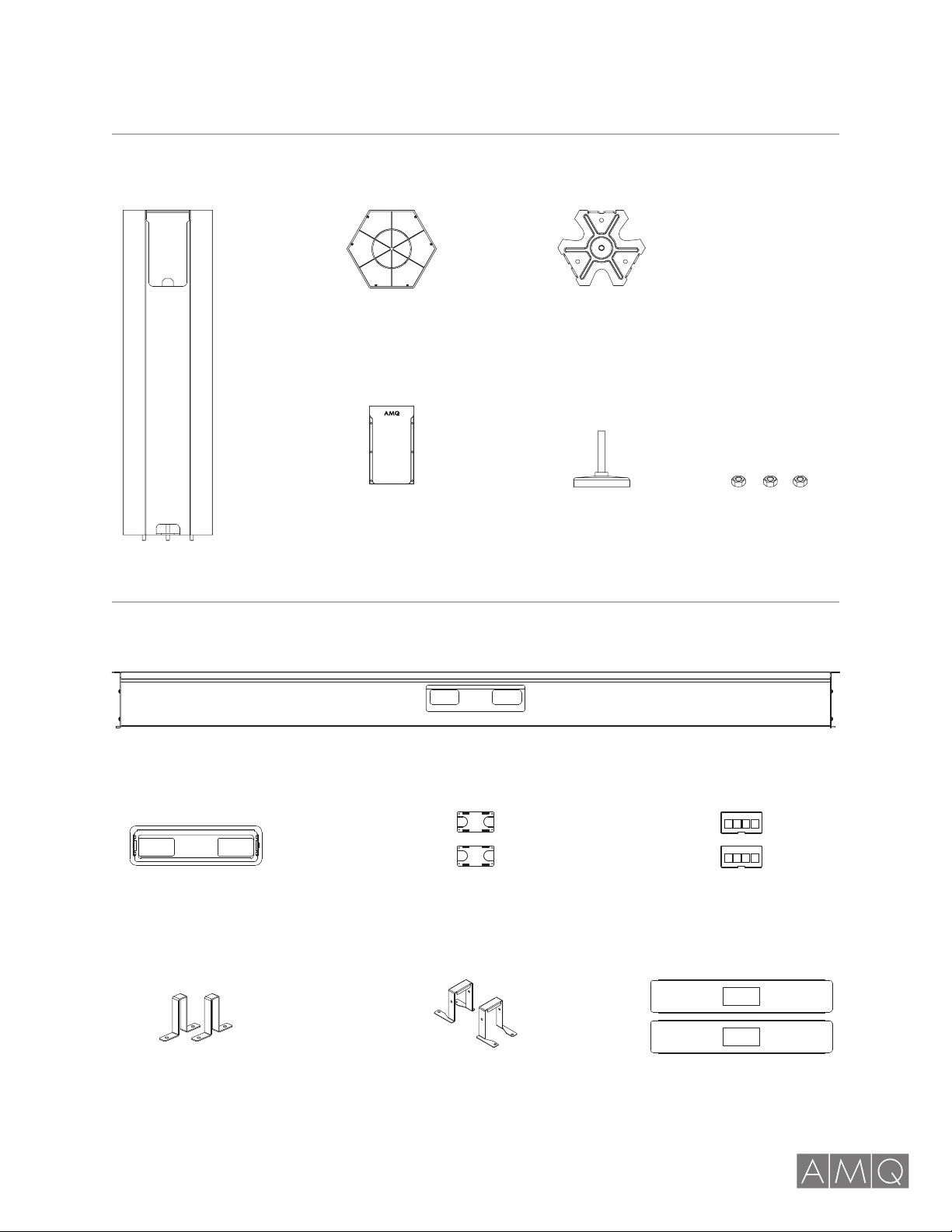
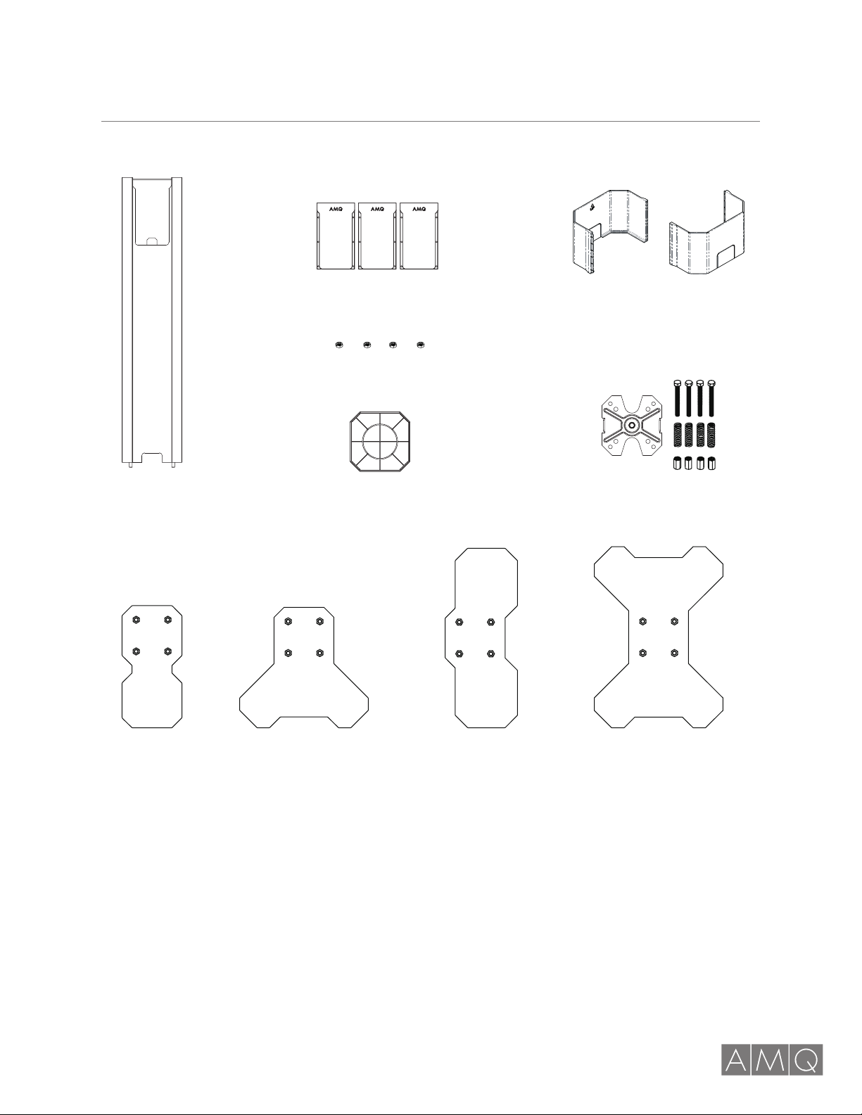
Components . . . . . . . . . . . . . . . . . . . . . . . . . . . . 4
Post, Beam Plate and Feet Assembly .........6
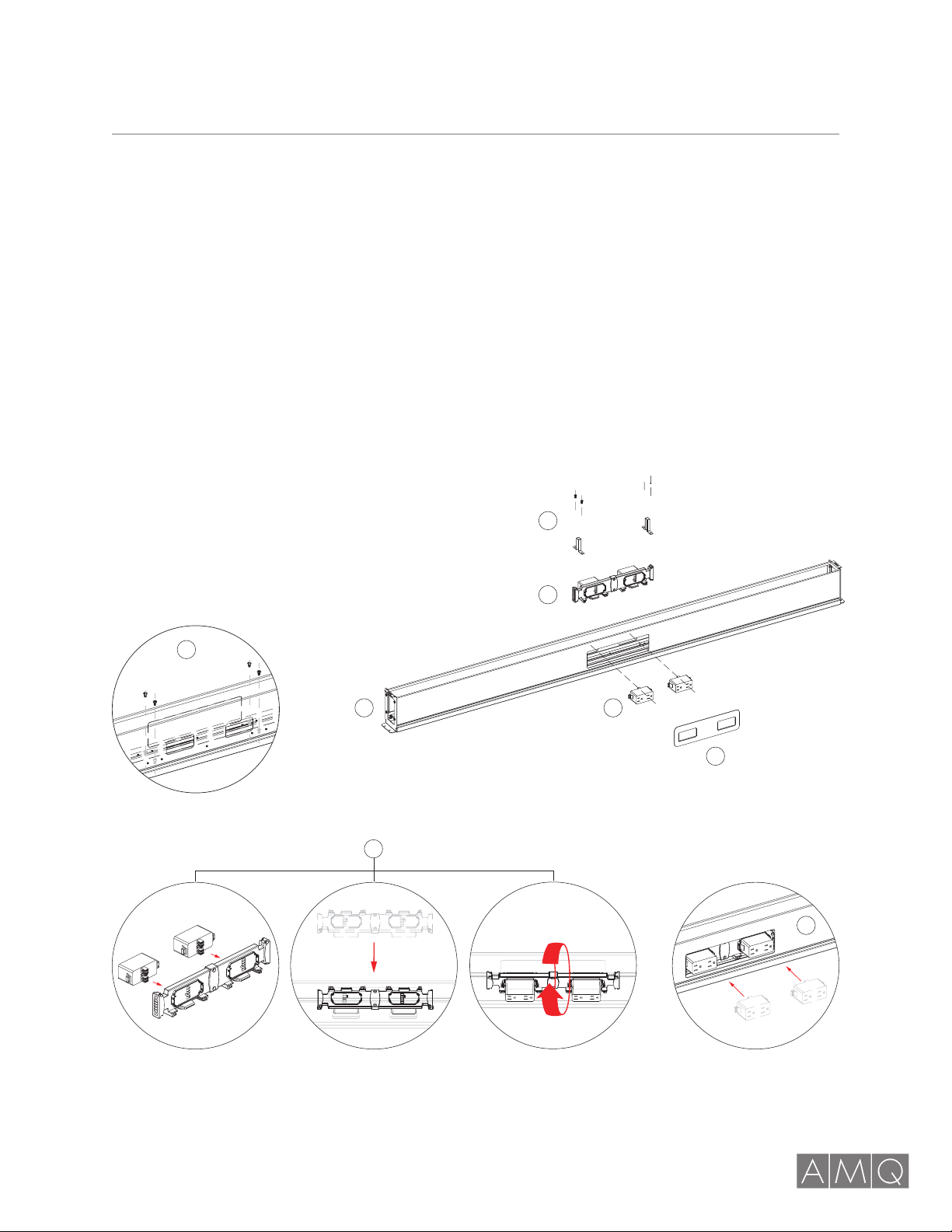
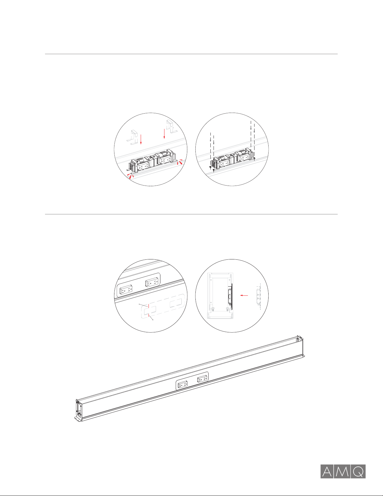
Beam Assembly (3-Circuit) .................7
Beam Assembly (4-Circuit) .................9
Footer and Base Plate Assembly............11
Post and Beam Assembly .................12
Entering Electric Base Feed................13
Cover and Trim Assembly .................14
Installing Caps and Covers – Post Sleeve .....15
Extending the Configuration................16
ILINE 90°/180° (4-WAY) ASSEMBLY ........... 17
Components . . . . . . . . . . . . . . . . . . . . . . . . . . . 18
Footer and Base Plate Assembly............20
Beam Assembly (3-Circuit) ................21
Beam Assembly (4-Circuit) ................23
Post, Beam Plate and Feet Assembly ........25
Installing Jumpers .......................26
Installing Caps and Covers ................27
Installing Caps and Covers – Post Sleve ......28
Installing Screens........................29
Final Adjustments........................30
Power Pole Retrofit .......................31

ILINE 120° (3-WAY)

ILINE INSTALLATION GUIDE | 4 amqsolutions.com
ILINE 120° (3-WAY)COMPONENTS
120° Vertical Post
Top Cap
Post Side Cover Glide, OEM Nuts
Base Plate
Horizontal Beam
Beam
3-Way Post
Face Plate Cover Receptacle
Cover
Data Face Plate
Junction Bracket
(3 circuit)
Junction Bracket
(4 circuit)
Bottom Beam Plate

ILINE INSTALLATION GUIDE | 5 amqsolutions.com
ILINE 120° (3-WAY)COMPONENTS
Vertical Post
Foot SRE
Top Cap
Foot SRC Foot DRE
Post Side Cover
Hex Nuts
Base Plate Kit
Foot DRC
Post Sleeve
4-Way Post

ILINE INSTALLATION GUIDE | 6 amqsolutions.com
ILINE 120° (3-WAY)PHASE 1 | Post, Beam Plate and Feet Assembly
Step 1 Step 2

ILINE INSTALLATION GUIDE | 7 amqsolutions.com
ILINE 120° (3-WAY)PHASE 2 | Beam Assembly (3-Circuit)
Step 1
Place beam upside down on the floor to reveal the beam canal. Disassemble the screws as indicated in
diagram 1. Put the four screws aside; these will be used in assembly step 4 shown on next page.
Step 2
Mount two receptacles on one side of the junction block. Insert the junction block slightly tilted as
shown in the in the diagram with the junction block without the receptacles facing the beam cutout.
Step 3
Clip on the receptacles to the junction block through the beam cutout.
5
4
3
3
2
2
1
1
Beam Cut-Out Side

ILINE INSTALLATION GUIDE | 8 amqsolutions.com
ILINE 120° (3-WAY)PHASE 2 | Beam Assembly (3-Circuit)
Step 4
Take three ILINE junction block (3 circuit) supporting brackets and position them as shown in the diagram.
Push it down until it can go no further. Assemble the four screws and the junction block supporting brackets
onto beam as shown in these diagrams.
Step 5
Place the face plate cover over the beam cutout. Position as shown in diagrams.
wide
narrow

ILINE INSTALLATION GUIDE | 9 amqsolutions.com
ILINE 120° (3-WAY)PHASE 2 | Beam Assembly (4-Circuit)
Step 1
Place beam upside down on the floor to reveal the beam canal. Disassemble the screws as indicated in
diagram 1. Put the four screws aside; they will be used in assembly step 4 shown on next page.
Step 2
Mount two receptacles on one side of the junction block. Insert the junction block slightly tilted like in the
diagram with the junction block without the receptacles facing the beam cut-out.
Step 3
Clip on the receptacles to the junction block through the beam cutout.
Beam Cut-Out Side
5
4
3
2
2
1
1
3

ILINE INSTALLATION GUIDE | 10 amqsolutions.com
ILINE 120° (3-WAY)PHASE 2 | Beam Assembly (4-Circuit)
Step 4
Take three ILINE junction block (4 circuit) supporting brackets and position them as shown in the diagram
below. Push it down until it can go no further. Assemble the four screws and the junction block supporting
brackets onto beam as shown in these diagrams.
Step 5
Place the face plate cover over the beam cutout. Position it as shown in diagrams.
wide
narrow

ILINE INSTALLATION GUIDE | 11 amqsolutions.com
ILINE 120° (3-WAY)PHASE 3 | Footer and Base Plate Assembly (4-Way Post)
Step 1
Insert a 3” bolt into each of the 2” compression springs.
Step 2
Insert the bolts and the compression springs into the
inner corner holes of the base plate.
Step 3
Screw the bolts into the coupling nuts until the bolt tips
are revealed.
Step 4
Screw the foot assembly to the foot plate nuts.
Step 5
Repeat Steps 1-4 for the all foot and base plates.
2
1
4” x 3” Bolt (5/16” x 18)
Foot Plate Nut
Foot Plate
4” x 3/4” Coupling Nut
(5/16” x 18)
Base Plate
4” x 2” Compression Spring
3
4

ILINE INSTALLATION GUIDE | 12 amqsolutions.com
ILINE 120° (3-WAY)PHASE 4 | Post and Beam Assembly
Step 1
Assemble the base plate, glide and post together.
Step 2
Slide the beam assembly into the open slots in the center of vertical post.
Fasten the beams using two screws on each end.
2
1

ILINE INSTALLATION GUIDE | 13 amqsolutions.com
ILINE 120° (3-WAY)PHASE 5 | Entering Electric Base Feed
Step 1
Take the exposed end of the power entry and feed through the center vertical post.
Step 2
Plug the power entry plug to the junction block.
NOTE: Depending on the floor plan, you may access the base feed through any of the posts in the assembly.
Use 1/4”-20 hex nut to tight down
posts on the footer-assemblies
Adjustable Wrench
2
1

ILINE INSTALLATION GUIDE | 14 amqsolutions.com
ILINE 120° (3-WAY)PHASE 6 | Cover and Trim Assembly
Step 1
Insert side covers into each exposed opening in vertical posts.
Step 2
Attach top cover to the center vertical post.
Step 3
Take two data face plates/bottom beam plates and snap them
onto each end of the underside of the beam assembly. Snap
on data face plates.
2
2
3
3
1
1

ILINE INSTALLATION GUIDE | 15 amqsolutions.com
ILINE 120° (3-WAY)PHASE 7 | Installing Caps and Covers – Post Sleeve
Step 1
Detach the pre-cut portion for the base feed access and line up with post.
Step 2
Align the Post Sleeve on both sides and apply pressure until pieces snap into place.
Step 3
Installed Post Sleeve. onto each end of the underside of the beam assembly. Snap on data face plates.
NOTE: After installing electrical, level for best aesthetic appearance.
2 31
Attached Post Sleeve

ILINE INSTALLATION GUIDE | 16 amqsolutions.com
ILINE 120° (3-WAY)PHASE 8 | Extending the Configuration
Step 1
Selecting the post that will accommodate the extension, replace the end foot plate (DRE) with a center foot.
Step 2
Open the top cap, then insert the new beam assembly.
Step 3
Feed the jumper through the beam canal and into the vertical post opening into the next beam assembly.
Step 4
Connect the jumper to each junction block. Re-attach the top cover onto the vertical post.
2
3
4
1
DRE
DRC

ILINE 90°/180° (4-WAY)

ILINE INSTALLATION GUIDE | 18 amqsolutions.com
ILINE 90°/180° (4-WAY)COMPONENTS
Vertical Post
Foot SRE
Top Cap
Foot SRC Foot DRE
Post Side Cover
Hex Nuts
Base Plate Kit
Foot DRC
Post Sleeve
4-Way Post

ILINE INSTALLATION GUIDE | 19 amqsolutions.com
ILINE 90°/180° (4-WAY)COMPONENTS
Horizontal Beam
Beam
Face Plate Cover Receptacle
Cover
Data Face Plate
Junction Bracket
(3 circuit)
Junction Bracket
(4 circuit)
Bottom Beam Plate

ILINE INSTALLATION GUIDE | 20 amqsolutions.com
ILINE 90°/180° (4-WAY)PHASE 1 | Footer and Base Plate Assembly
Step 1
Insert a 3” bolt into each of the 2” compression springs.
Step 2
Insert the bolts and the compression springs into the
inner corner holes of the base plate.
Step 3
Screw the bolts into the coupling nuts until the bolt tips
are revealed.
Step 4
Screw the foot assembly to the foot plate nuts.
Step 5
Repeat Steps 1-4 for the all foot and base plates.
2
1
4” x 3” Bolt (5/16” x 18)
Foot Plate Nut
Foot Plate
4” x 3/4” Coupling Nut
(5/16” x 18)
Base Plate
4” x 2” Compression Spring
3
4
Other manuals for ILINE
1
Table of contents
Other AMQ Office Equipment manuals
Popular Office Equipment manuals by other brands

hushoffice
hushoffice hushwork HUS-BX-009 Maintenance and safety manual

Formax
Formax CT-20 Assembly, operation and parts manual

GBC
GBC Coilbind C100 Nstruction manual

PrePRESS
PrePRESS PANTHER PRO/46 Technical manual

Framery Q
Framery Q Maggie installation instructions

Vicoustic
Vicoustic VicBooth Office installation manual