manuals.online logo
Brands
  1. Home
  2. •
  3. Brands
  4. •
  5. GREAT PLAINS
  6. •
  7. Drill
  8. •
  9. GREAT PLAINS 1206NT User manual

GREAT PLAINS 1206NT User manual

Manufacturing, Inc.
www.greatplainsmfg.com
© Copyright 2017 Printed 12/03/2020 150-166Q
EN
Table of Contents
Table of Contents
ORIGINAL INSTRUCTIONS
Pre-Delivery Instructions
1206NT
End-Wheel, No-Till Drill
Read this manual entirely. When you see this symbol, the subsequent
instructions and warnings are serious - follow without exception.
Your life and the lives of others depend on it!
Illustrations may show optional equipment not supplied with standard unit.
EN
Table of Contents
Table of Contents
1206NT Cover iii
2020-12-03 Cover 150-166Q
© Copyright 2012, 2014, 2015, 2017 All rights Reserved
Great Plains Manufacturing, Inc. provides this publication “as is” without warranty of any kind, either expressed or implied. While every precaution has been
taken in the preparation of this manual, Great Plains Manufacturing, Inc. assumes no responsibility for errors or omissions. Neither is any liability assumed
for damages resulting from the use of the information contained herein. Great Plains Manufacturing, Inc. reserves the right to revise and improve its products
as it sees fit. This publication describes the state of this product at the time of its publication, and may not reflect the product in the future.
Trademarks of Great Plains Manufacturing, Inc. include: AccuShot, Max-Chisel, Row-Pro,
Singulator Plus, Short Disk, Swath Command, Terra-Tine, Ultra-Chisel, and X-Press.
Registered Trademarks of Great Plains Manufacturing, Inc. include: Air-Pro, Clear-Shot, Discovator, Great Plains, Land Pride, MeterCone,
Nutri-Pro, Seed-Lok, Solid Stand, Terra-Guard, Turbo-Chisel, Turbo-Chopper, Turbo-Max, Turbo-Till, Ultra-Till, Whirlfilter, and Yield-Pro.
Brand and Product Names that appear and are owned by others are trademarks of their respective owners.
Printed in the United States of America
Table of Contents
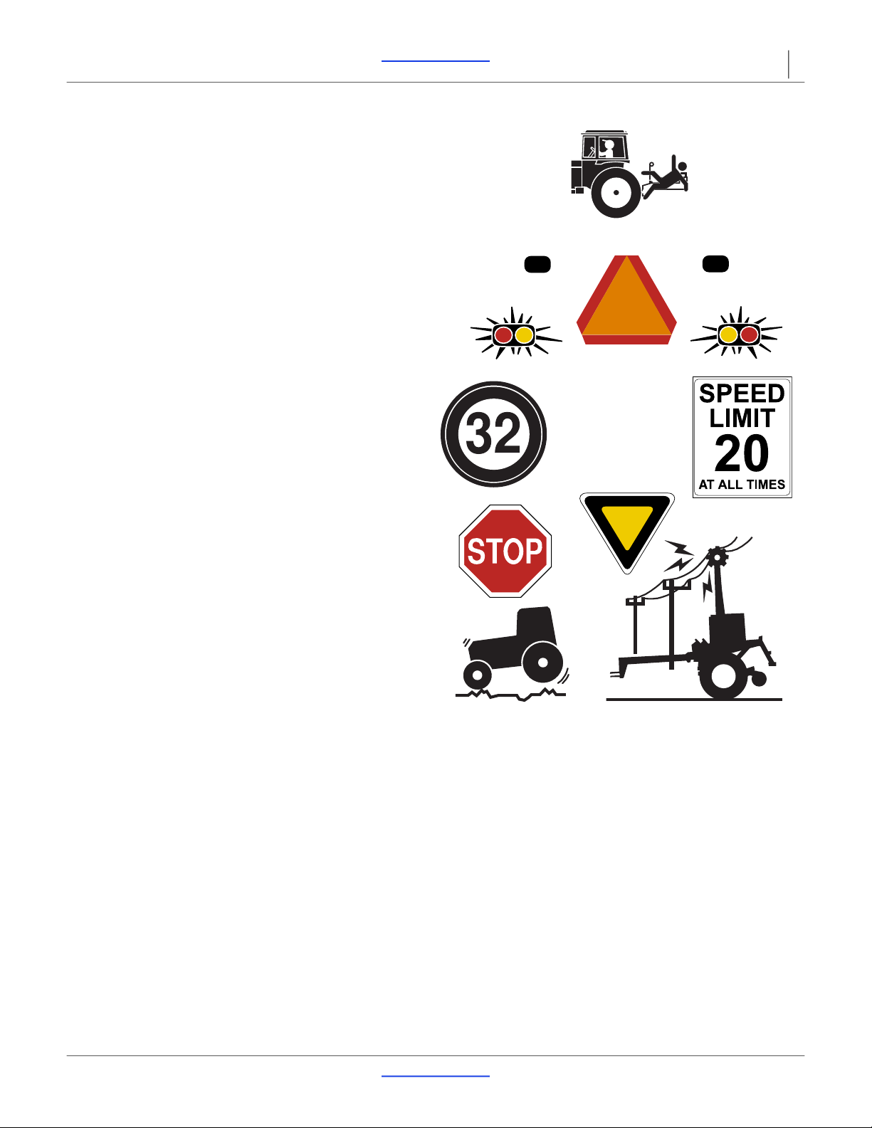
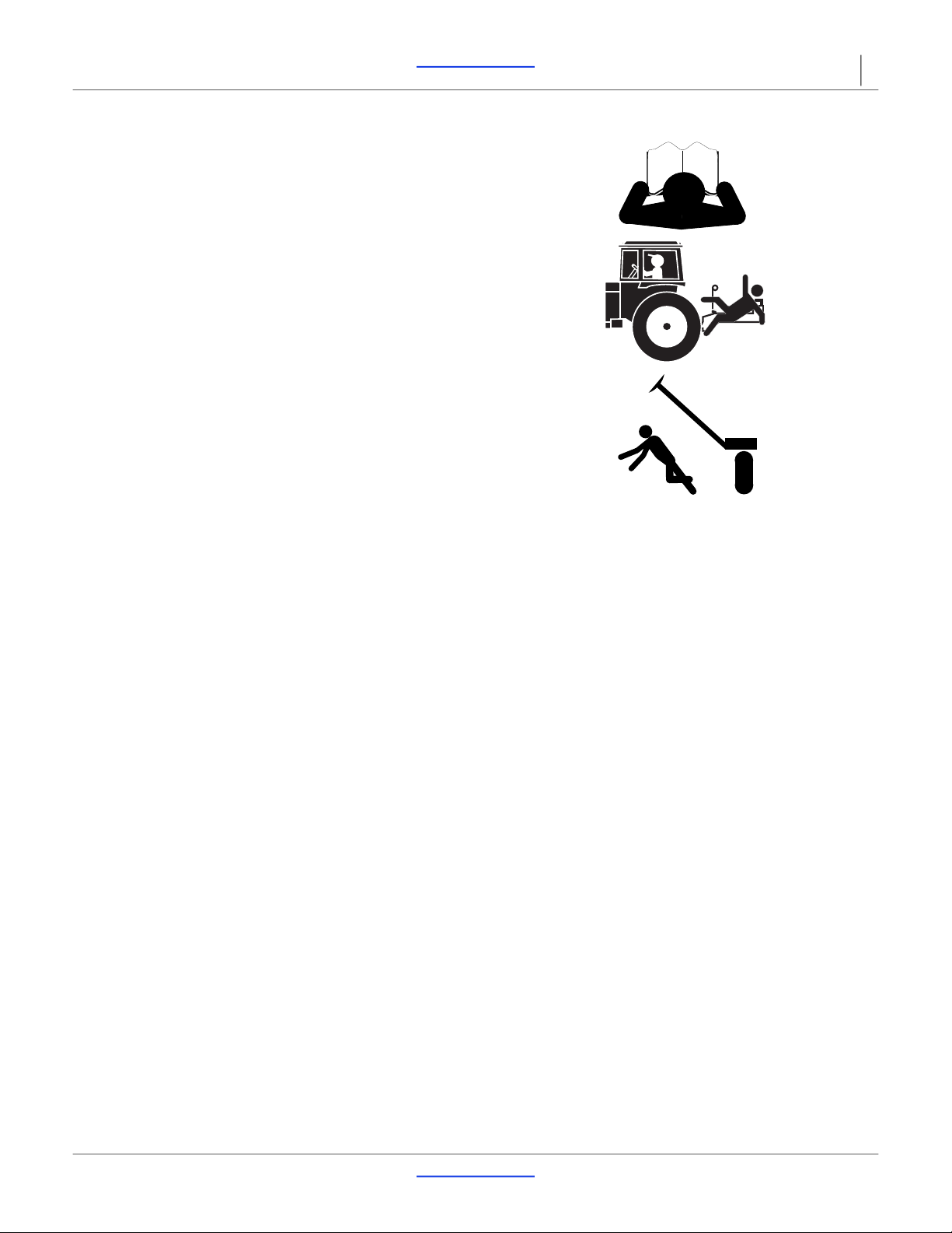
Important Safety Information.................................................1
Safety Decals ....................................................................5
Introduction.............................................................................6
Description of Unit .............................................................6
Models covered .................................................................6
Document Family ......................................................6
Using This Manual.............................................................7
Definitions..........................................................................7
Preparation..............................................................................8
Tools Required ..................................................................8
Assembly and Setup Assistance .......................................8
Unloading the Truck ...............................................................9
Assembly...............................................................................10
Tools Required ................................................................10
Pre-Assembly Checklist...................................................10
Removing Tongue, if Shipped Attached ..........................11
Prepare Folding Tongue..................................................11
Install Tongue ..................................................................12
Lighting and Hydraulic Hoses..........................................13
Route Hoses and Harnesses ...................................13
Setup......................................................................................15
Hitching Tractor to Drill....................................................15
Clevis Hitch Assembly..............................................15
Adjust Hitch Height...................................................15
Hitch Heights............................................................16
Adjusting Either Hitch...............................................17
Safety Chain.............................................................18
Jack Storage ............................................................18
Hydraulic Hookup.....................................................19
Transport Lift Cylinder Flow Setting .........................19
Bleeding Hydraulics .................................................20
Rephasing Cylinders ................................................21
Leveling Drill.............................................................21
Appendix ...............................................................................22
Tire Size and Pressure....................................................22
Torque Values Chart .......................................................22
Hydraulic Connectors and Torque...................................23
Cover
Cover
2020-12-03 Table of Contents 150-166Q
1206NT Table of Contents 1
Important Safety Information
Look for Safety Symbol
The SAFETY ALERT SYMBOL indicates there is a
potential hazard to personal safety involved and extra
safety precaution must be taken. When you see this
symbol, be alert and carefully read the message that
follows it. In addition to design and configuration of
equipment, hazard control and accident prevention are
dependent upon the awareness, concern, prudence and
proper training of personnel involved in the operation,
transport, maintenance and storage of equipment.
Be Aware of Signal Words
Signal words designate a degree or level of hazard
seriousness.
DANGER indicates an imminently hazardous situation
which, if not avoided, will result in death or serious injury.
This signal word is limited to the most extreme situations,
typically for machine components that, for functional
purposes, cannot be guarded.
WARNING indicates a potentially hazardous situation
which, if not avoided, could result in death or serious
injury, and includes hazards that are exposed when
guards are removed. It may also be used to alert against
unsafe practices.
CAUTION indicates a potentially hazardous situation
which, if not avoided, may result in minor or moderate
injury. It may also be used to alert against unsafe
practices.
Prepare for Emergencies
Be prepared if a fire starts
Keep a first aid kit and fire extinguisher handy.
Keep emergency numbers for doctor, ambulance, hospital
and fire department near phone.
Be Familiar with Safety Decals
Read and understand “Safety Decals” on page 5,
thoroughly.
Read all instructions noted on the decals.
Keep decals clean. Replace damaged, faded and illegible
decals.
2020-12-03 Table of Contents 150-166Q
1206NT Table of Contents Important Safety Information 2
Wear Protective Equipment
Wear protective clothing and equipment.
Wear clothing and equipment appropriate for the job.
Avoid loose-fitting clothing.
Because prolonged exposure to loud noise can cause
hearing impairment or hearing loss, wear suitable
hearing protection such as earmuffs or earplugs.
Because operating equipment safely requires your full
attention, avoid wearing radio headphones while
operating machinery.
Avoid High Pressure Fluids
Escaping fluid under pressure can penetrate the skin,
causing serious injury.
Avoid the hazard by relieving pressure before
disconnecting hydraulic lines.
Use a piece of paper or cardboard, NOT BODY PARTS, to
check for suspected leaks.
Wear protective gloves and safety glasses or goggles when
working with hydraulic systems.
If an accident occurs, seek immediate medical assistance
from a physician familiar with this type of injury.
If an accident occurs, see a doctor immediately. Any fluid
injected into the skin must be surgically removed within a
few hours or gangrene can result.
Handle Chemicals Properly
Read and follow chemical manufacturer’s instructions.
Wear protective clothing.
Handle all chemicals with care.
Agricultural chemicals can be dangerous. Improper use
can seriously injure persons, animals, plants, soil and
property.
Inhaling smoke from any type of chemical fire is a serious
health hazard.
Store or dispose of unused chemicals as specified by the
chemical manufacturer.
Immediately and thoroughly flush any area of the body
that is contaminated by chemicals.
If chemical is swallowed, carefully follow the chemical
manufacturer’s recommendations and consult with a
doctor.
If persons are exposed to a chemical in a way that could
affect their health, consult a doctor immediately with the
chemical label or container in hand. Any delay could
cause serious illness or death.
Dispose of empty chemical containers properly. By law
rinsing of the used chemical container must be repeated
three times. Puncture the container to prevent future use.
An alternative is to jet-rinse or pressure rinse the
container.
After working with chemicals, wash hands and face before
eating. Shower when application is completed for the day.
Never wash out the tanks within 100 feet (30m) of any
freshwater source or in a car wash.
Rinse out the tank. Apply rinse water on last field treated.
1206NT Table of Contents Important Safety Information 3
2020-12-03 Table of Contents 150-166Q
Keep Riders Off Machinery
Riders obstruct the operator’s view. Riders could be
struck by foreign objects or thrown from the machine.
Never allow children to operate equipment.
Keep all bystanders away from machine during operation.
Use Safety Lights and Devices
Slow-moving tractors and towed implements can create
a hazard when driven on public roads. They are difficult
to see, especially at night.
Use flashing warning lights and turn signals whenever
driving on public roads.
Use lights and devices provided with implement
Transport Machinery Safely
Maximum transport speed for implement is20 mph
(32 km/h). Some rough terrains require a slower speed.
Sudden braking can cause a towed load to swerve and
upset.
Do not exceed 20 mph (32 km/h). Never travel speeds
which do not allow adequate control of steering and
stopping. Reduce speed if towed load is not equipped with
brakes.
Comply with state and local laws.
Do not tow an implement that, when fully loaded, weighs
more than 1.5 times the weight of towing vehicle.
Carry reflectors or flags to mark drill in case of
breakdown on the road.
Keep clear of overhead power lines and other
obstructions when transporting. Refer to transport
dimensions in the Operator’s Manual.
2020-12-03 Table of Contents 150-166Q
1206NT Table of Contents Important Safety Information 4
Shutdown and Storage
Lower drill, put tractor in park, turn off engine, and
remove the key.
Secure drill using blocks and supports provided.
Detach and store drill in an area where children normally
do not play.Use A Safety Chain
Use a safety chain to help control drawn machinery
should it separate from tractor drawbar.
Use a chain with a strength rating equal to or greater than
the gross weight of towed machinery.
Attach chain to tractor drawbar support or other specified
anchor location. Allow only enough slack in chain to
permit turning.
Replace chain if any links or end fittings are broken,
stretched or damaged.
Do not use safety chain for towing.
Tire Safety
Tire changing can be dangerous and must be performed
by trained personnel using correct tools and equipment.
When inflating tires, use a clip-on chuck and extension
hose long enough for you to stand to one side–not in front
of or over tire assembly. Use a safety cage if available.
When removing and installing wheels, use wheel-handling
equipment adequate for weight involved.
Practice Safe Maintenance
Understand procedure before doing work. Use proper
tools and equipment. Refer to this manual for additional
information.
Work in a clean, dry area.
Lower the drill, put tractor in park, turn off engine, and
remove key before performing maintenance.
Make sure all moving parts have stopped and all system
pressure is relieved.
Allow drill to cool completely.
Disconnect battery ground cable (-) before servicing or
adjusting electrical systems or before welding on drill.
Inspect all parts. Make sure parts are in good condition
and installed properly.
Remove buildup of grease, oil, or debris.
Remove all tools and unused parts from drill before
operation.
1206NT Table of Contents Important Safety Information 5
2020-12-03 Table of Contents 150-166Q
Safety At All Times
Thoroughly read and understand the instructions in this
manual before operation. Read all instructions noted on
the safety decals.
Be familiar with all drill functions.
Operate machinery from the driver’s seat only.
Do not leave drill unattended with tractor engine running.
Do not dismount a moving tractor. Dismounting a moving
tractor could cause serious injury or death.
Do not stand between the tractor and drill during
hitching.
Keep hands, feet and clothing away from power-driven
parts.
Wear snug-fitting clothing to avoid entanglement with
moving parts.
Watch out for wires, trees, etc., when folding and raising
drill. Make sure all persons are clear of working area.
Do not turn tractor too tightly, causing drill to ride up on
wheels. This could cause personal injury or equipment
damage.
Safety Decals
Safety Reflectors and Decals
Your implement comes equipped with all lights, safety
reflectors and decals in place. They were designed to
help you safely operate your implement.
Read and follow decal directions.
Keep lights in operating condition.
Keep all safety decals clean and legible.
Replace all damaged or missing decals. Order new decals
from your Great Plains dealer. Refer to this section for
proper decal placement.
When ordering new parts or components, also request
corresponding safety decals.To install new decals:
To install new decals:
1. Clean the area on which the decal is to be placed.
2. Peel backing from decal. Press firmly on surface,
being careful not to cause air bubbles under decal.
2020-12-03 Table of Contents 150-166Q
1206NT Table of Contents 6
Introduction
Great Plains Manufacturing wants you to be satisfied
with any new machine delivered by the Great Plains
Trucking network. To ease the assembly task and
produce a properly working machine, read this entire
manual before assembling or setting up new equipment.
Description of Unit
The 1206NT No-Till Drill is a 12' grain drill of end wheel
design which couples Great Plains spring mounted
coulter with a straight arm design of our solid stand
opener to achieve no-till drilling capabilities. The end
wheel design keeps the ground-working components in
line with the end wheels for accurate coulter depth and
seed placement over uneven terrain and allows the unit
to follow field curves without side-loading the openers.
Models covered
Document Family
1206NT-1410 End Wheel No-Till 12 ft. 10 in.
1206NT-1808 End Wheel No-Till 12 ft. 8 in.
1206NT-1975 End Wheel No-Till 12 ft. 7-1/2 in.
1206NT-2007 End Wheel No-Till 12 ft. 7 in.
150-166Q Pre-Delivery Manual (this document)
150-166M Operator Manual
150-166P 1206NT Parts Manual
150-166B Seed Rate Manual
68367
Figure 1
1206NT No-Till Drill
1206NT Table of Contents Introduction 7
2020-12-03 Table of Contents 150-166Q
Using This Manual
This manual was written to help you assemble and
prepare the new machine for the customer. The manual
includes instructions for assembly and setup. Read this
manual and follow the recommendations for safe,
efficient and proper assembly and setup.
An operator’s manual is also provided with the new
machine. Read and understand “Important Safety
Information” and “Operating Instructions” in the
operator’s manual before assembling the machine. As a
reference, keep the operator’s manual on hand while
assembling.
The information in this manual is current at printing.
Some parts may change to assure top performance.
Definitions
The following terms are used throughout this manual.
Right and left as used in this manual are determined by
facing the direction the machine will travel while in use
unless otherwise stated.
Paragraphs in this format present a crucial point of information
related to the current topic.
Read and follow the directions to:
- remain safe,
- avoid serious damage to equipment and
- ensure desired field results.
NOTE:
Useful information about the preceding topic.
Further Assistance
For additional help with understanding these assembly
instructions or for any other assembly or setup related
questions, please contact our service department at the
following address:
Great Plains Service Department
1525 E. North St.
P.O. Box 5060
Salina, KS 67402-5060
Or call us at (800) 270-9302 to speak over the phone
with a service representative.
Copies of this machine’s operator manual are available
by mail or online. Please visit www.greatplainsag.com
and follow the product link for information on your
machine.
2020-12-03 Table of Contents 150-166Q
1206NT Table of Contents 8
Preparation
Step-by-step instructions for assembling the drill begin in
the next section of the manual. Before commencing
work, review the Tools Required and Pre-Assembly
Checklist to make sure you have all necessary parts and
equipment.
The drill is shipped via flat bed truck. It is the dealer’s
responsibility to unload the new machine. Unload all
equipment before beginning assembly.
The general sequence of work is:
Assembly
a. Unload frame, tongue and accessories from
truck.
b. Assemble tongue to mainframe.
c. Route hoses and harness.
Setup
a. Adjust hitch height.
b. Hitch to tractor.
c. Level drill.
d. Bleed hydraulics.
e. Install accessories and Options.
f. Set coulter depth control. (Do not skip this
step!)
Tools Required
•Lift or overhead hoist with a minimum lifting capacity
of 8000 pounds (3628 kg).
•A tractor of sufficient size and horsepower with
remote hydraulics. Refer to “Specifications and
Capacities” in the Operator’s Manual.
If the tractor to be used with the drill is not available
during setup, obtain a measurement of its hitch
height.
•General hand tools
•Jack stands or blocks and safety chain.
NOTE:
You need about 1 gallon (3.8 liters) of hydraulic oil to
refill the tractor hydraulic reservoir after initial
bleeding and cycling of the hydraulic system.
Assembly and Setup Assistance
To order additional copies of predelivery instructions or
operator’s and parts manuals, write to the following
address. Include model numbers in all correspondence.
Do not attempt any assembly work while the drill is on the
truck.
2020-12-03 Table of Contents 150-166Q
1206NT Table of Contents 9
Unloading the Truck
Hoist drill from above.
Do not fork-lift from beneath drill.
There are no suitable lift points.
Do not hoist via lugs after tongue is installed in the working
position.
Drill is not balanced at lugs with tongue installed.
1. If the tongue is shipped separate from the machine,
use hoist or lift to remove the tongue from truck.
2. Use hoist or lift to remove any accessories from
truck.
Do not install accessories while the machine is on the truck.
3. Secure lifting lines to the lugs above the lift cylinder
eyebolts. Prior to tongue installation, these lugs
permit nearly level lifting of the drill. The lugs are
marked with lift point decals.
4. Lift drill from truck and lower at assembly point.
5. Remove small parts from main seed box.

21718
Figure 2
Hoisting Lines
2020-12-03 Table of Contents 150-166Q
1206NT Table of Contents 10
Assembly
The following headings are step-by-step instructions for
assembling the drill. Begin with “Tools Required” and
“Pre-Assembly Checklist” to make sure you have all
necessary parts and equipment. Follow each step to make
the job as quick and safe as possible and produce a properly
working machine.
The drill is shipped via flat bed truck. It is the dealer’s
responsibility to unload the new machine. Unload all
equipment before beginning assembly.
Do not attempt any assembly work while the machine is on the
truck.
Tools Required
•Fork lift, overhead hoist, or loader
•General hand tools.
Pre-Assembly Checklist
1. Before assembling, read and understand the safety
information in this book.
2. Have at least two people on hand while assembling.
3. Make sure assembly area is level and free of obstructions
(preferably an open concrete area).
4. Have all major components.
5. Have all fasteners and pins shipped with the drill.
If a pre-assembled part or fastener is temporarily removed,
remember where it goes. Keep the parts separated.
6. Have a copy of the parts manual on hand. If unsure of
proper placement or use of any part or fastener, refer to
the parts manual.
7. Check that all working parts are moving freely, bolts are
tight, and cotter pins are spread.
8. Check for proper tension and alignment on all drive
chains.
9. Check that all safety decals and reflectors are located
correctly and legible. Replace if improperly located or
damaged. Refer to “Safety Decals” in the operator’s
manual.
10. Inflate tires to recommended pressure as listed in the
“Appendix” on page 22. Tighten wheel bolts as specified
on “Torque Values Chart” on page 22.
Parts
Manual
1206NT Table of Contents Assembly 11
2020-12-03 Table of Contents 150-166Q
Removing Tongue, if Shipped Attached
1. Use hoist or lift to support the front of the drill while
the tongue is being removed and installed.
2. Use hoist or lift to support the tongue (1).
3. A shipping bracket (2) is used to hold the tongue to
the mainframe during shipping. Carefully remove
and discard the shipping bracket and the mounting
hardware (3).
4. Lower the tongue to the floor so the rear jack
mounting tube (4) is on the top of the tongue.
Prepare Folding Tongue
1. If tongue is already unfolded, continue at Install
Tongue.
2. Support the forward end of the rear tongue weldment
(1) off the ground by at least 6 in. (15cm). Use a
hoist line or place a block under it.
3. Remove the locking pin (2) from the folding tongue.
4. Swing the folding tongue forward and secure with
bolts (3), lock washers (4), and nuts (5).
5. Install the locking pin in front half of the tongue and
the lock tube (6) on rear tongue weldment. Install the
hair pin.
3
1
2
4
36792
Figure 3
Removing Tongue from Mainframe
2
3
4
5
28119
6
1
Figure 4
Unfolding Tongue
2020-12-03 Table of Contents 150-166Q
1206NT Table of Contents Assembly 12
Install Tongue
The following instruction apply to both the standard and
the folding tongue.
1. Remove the six mounting bolts and four U-bolts from
the tongue.
2. Connect hoist lines (1) at available hitch holes (2),
and around rear tongue tube (3), behind brace tubes
(4).
Crushing hazard. You may be severely injured by frames if they
fall. Always support frame sections with jack stands or blocks
before working under frames raised off ground.
3. Align the mounting plate (5) on the tongue with the
mounting plate (6) on the mainframe. Insert a bolt (7)
at the top center hole and secure finger tight with
lock washer and nut.
4. Level tongue from side to side relative to mainframe.
Install the remainder of the hardware in the center
mounting plate. Fasten finger tight.
5. Insert all four U-bolts (8), and install lock washers,
and nuts. Fasten finger tight.
6. Tighten the all of the nuts the on the bolts and
U-bolts to 265 ft-lb (350 Nm).
7. Remove hair pin and clevis pin from the jack (9).
Install the jack on the front jack mounting tube (10).
Put the jack in the vertical position and install the
clevis pin and hair pin.
8. Crank the jack down just until the weight of the
forward end of the tongue is supported by the jack.
9. Remove all lifting equipment and any blocks.
1
2
4
3
36791
Figure 5
Installing Tongue
5
8
7
6
36791
Figure 6
Fastening Tongue
9
10
36733
Figure 7
Secure Tongue
1206NT Table of Contents Assembly 13
2020-12-03 Table of Contents 150-166Q
Lighting and Hydraulic Hoses
The hydraulic hoses are pre-installed on the drill and are
tied to the hitch mounting plate.
The lights may be assembled or may be shipped in the
seed box or separately to prevent damage to the lighting
system during transport and loading.
If the drill is delivered with the lights not assembled, the dealer
must assemble the lights on the drill prior to selling the drill.
1. At one end of the drill, install a spacer (1), lamp
bracket (2), and handle (3) using two 1/2-13 x 1 inch
bolts (4) and two flange lock nuts (5).
NOTE:
Make sure the horizontal flange of the lamp bracket is
toward the front of the drill.
2. Install an amber lamp (6) to the bracket with two
1/4-20x3/4 inch self tapping screws (7).
3. Install a hose clip (8) to the lamp bracket with a
3/8-16x3/4 bolt (9), lock washer (10), and nut (11).
4. Secure the wiring harness to the hose clip.
5. Place a red reflector (12) to the lamp bracket facing
rearward.
6. Repeat the procedure for the other amber lamp.
Route Hoses and Harnesses
1. Connect the rear lighting harness (1) to the red
lamps under the walkboard and amber lamps.
2. Fasten the module (2) of the middle lighting harness
(3) to the tongue with 1/4-20x1 inch bolts (4) and
nuts (5). Connect the middle lighting harness to the
rear wiring harness.
3. Connect the front lighting harness (6) to the middle
lighting harness. Use wire ties (7) to fasten the wiring
harnesses to the drill.
4. Tape or tie the tractor connector (8) on the front
lighting harness to the hose bundle at the
quick-disconnect fittings.
5. Remove the color-coded hose grips before
attempting to route the hydraulic hoses through the
tongue.
2
1
1
4
3
2
5
6
7
68366
1
Figure 8
Amber Lamp Installation
9
8
68372
12
10
11
Figure 9
Reflector Installation
3
1
68366A
2
6
7
8
4
5
Figure 10
Connect Light Harnesses
2020-12-03 Table of Contents 150-166Q
1206NT Table of Contents Assembly 14
6. Once hydraulic hoses are routed through the tongue,
attach color-coded grips to the correct hydraulic
hose. Retract grip and hose go to the rod end of the
cylinder. Extend grip and hose go to the base end of
the cylinder.
7. Route the hose and lighting harness bundle (9)
under the rear cross-tube of the tongue, into the
access hole (10), and out the front of the tongue tube
near the hitch.
8. Un-tape/tie the lighting harness. Fasten the lighting
connector and hydraulic quick disconnect fittings to
the holder plate (11). 936733
11
10
Figure 11
Route Hoses and Harness
2020-12-03 Table of Contents 150-166Q
1206NT Table of Contents 15
Setup
Deferred Option Assembly
Some optional drill features are not factory-installed, or
may have been ordered for field installation. Although
they are “assembly” items, they may require a hitched
tractor, and/or that drill hydraulics be functioning (for drill
lift/lower). Do not install optional features until the setup
procedure is complete. These options include their own
Installation Instructions.
Hitching Tractor to Drill
Crushing Hazard:
Do not stand or place any part of your body between drill and
moving tractor. You may be severely injured or killed by being
crushed between the tractor and drill. Stop tractor engine and
set park brake before installing hitch pin and attaching hoses.
Clevis Hitch Assembly
1. Insert upper hitch plate (1) into clevis hitch (2) with a
spacer tube (3) on each side of ball swivel.
2. Bolt in place with 1 x 5-1/2 inch bolt (4), flat washer
(5) and Nylock nut (6).
Adjust Hitch Height
Although the specified hitch option (clevis or pintle) is
factory-installed, it may not be at ideal tractor height.
If a clevis hitch was specified, it needs to be assembled
on the tractor drawbar.
34901
Figure 12
Hitch Assembly
2020-12-03 Table of Contents 150-166Q
1206NT Table of Contents Setup 16
Hitch Heights
The drill operates more effectively if the tongue is level in
field position.
The drill needs to be lowered (in field position) for the
following measurements and any adjustments.
1. If the intended tractor is available, and has an
adjustable or invertible drawbar, set the drawbar to
the operator’s preferred height. If the tractor is not
available, obtain a measurement of the height:
• clevis hitch: to the bottom surface of the drawbar
• pintle hitch: to the top surface of the lower claw.
2. Use the parking jack to adjust the tongue until it is
level from front to back. If the work surface itself is
level, use a carpenter’s level on top of the tongue
tube. When level, the top of the tube is
approximately 26 34in. (68cm) above ground at the
hitch.
3. Measure from ground to:
• clevis hitch: to the top surface of lower lug
• pintle hitch: to the bottom of ring.
Figure 13
Hitch Heights (Tongue Level in Field Position)
28115
Clevis
Pintle
24.0 in
61.0 cm 21.0 in
53.4 cm
20.0 in
50.8cm 18.0 in
45.7 cm
17.0 in
43.2 cm 14 in
35.6 cm
23.5 in
59.7 cm 19.5 in
49.5 cm
20.5 in
52.1 cm 17.5 in
44.5 cm
16.5 in
41.9 cm 13.5 in
34.3 cm

Other GREAT PLAINS Drill manuals

GREAT PLAINS 3S-5000 Series User manual

GREAT PLAINS

GREAT PLAINS 3S-5000 Series User manual

GREAT PLAINS Spartan 607 User manual

GREAT PLAINS

GREAT PLAINS Spartan 607 User manual

GREAT PLAINS 1520F User manual

GREAT PLAINS

GREAT PLAINS 1520F User manual

GREAT PLAINS BD7600 User manual

GREAT PLAINS

GREAT PLAINS BD7600 User manual

GREAT PLAINS CTA4500 User manual

GREAT PLAINS

GREAT PLAINS CTA4500 User manual

GREAT PLAINS 2N-3020 User manual

GREAT PLAINS

GREAT PLAINS 2N-3020 User manual

GREAT PLAINS 1300 User manual

GREAT PLAINS

GREAT PLAINS 1300 User manual

GREAT PLAINS 2S-2600 User manual

GREAT PLAINS

GREAT PLAINS 2S-2600 User manual

GREAT PLAINS 3S-3000 Series User manual

GREAT PLAINS

GREAT PLAINS 3S-3000 Series User manual

GREAT PLAINS 1982 Programming manual

GREAT PLAINS

GREAT PLAINS 1982 Programming manual

GREAT PLAINS FCA 4500-7275 User manual

GREAT PLAINS

GREAT PLAINS FCA 4500-7275 User manual

GREAT PLAINS 3P500 User manual

GREAT PLAINS

GREAT PLAINS 3P500 User manual

Popular Drill manuals by other brands

Black & Decker LDX116 instruction manual

Black & Decker

Black & Decker LDX116 instruction manual

Makita HP2051J instruction manual

Makita

Makita HP2051J instruction manual

Klutch 49564 owner's manual

Klutch

Klutch 49564 owner's manual

Makita DDF459Z instruction manual

Makita

Makita DDF459Z instruction manual

Husqvarna DM650 Operator's manual

Husqvarna

Husqvarna DM650 Operator's manual

Stanley FatMax V20 SFMCD700 Original instructions

Stanley

Stanley FatMax V20 SFMCD700 Original instructions

Makita 6409 instruction manual

Makita

Makita 6409 instruction manual

Milwaukee M12 FDD user manual

Milwaukee

Milwaukee M12 FDD user manual

Energer ENB463DRL Safety and operating manual

Energer

Energer ENB463DRL Safety and operating manual

Bosch Professional GSB 12V-15N Original instructions

Bosch

Bosch Professional GSB 12V-15N Original instructions

Desoutter Industrial Tools C Series user manual

Desoutter

Desoutter Industrial Tools C Series user manual

Skil 6475 instructions

Skil

Skil 6475 instructions

Draper GD16 Instructions for use

Draper

Draper GD16 Instructions for use

MasterCraft 5268 instruction manual

MasterCraft

MasterCraft 5268 instruction manual

Graphite 58G010 instruction manual

Graphite

Graphite 58G010 instruction manual

Draper STORMFORCE CD108SF instructions

Draper

Draper STORMFORCE CD108SF instructions

VONROC PD501AC Original instructions

VONROC

VONROC PD501AC Original instructions

Ozito PXBHS-100 instruction manual

Ozito

Ozito PXBHS-100 instruction manual

manuals.online logo
manuals.online logoBrands
  • About & Mission
  • Contact us
  • Privacy Policy
  • Terms and Conditions

Copyright 2025 Manuals.Online. All Rights Reserved.