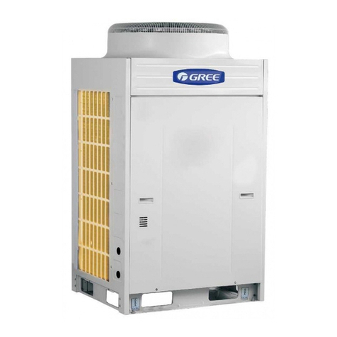
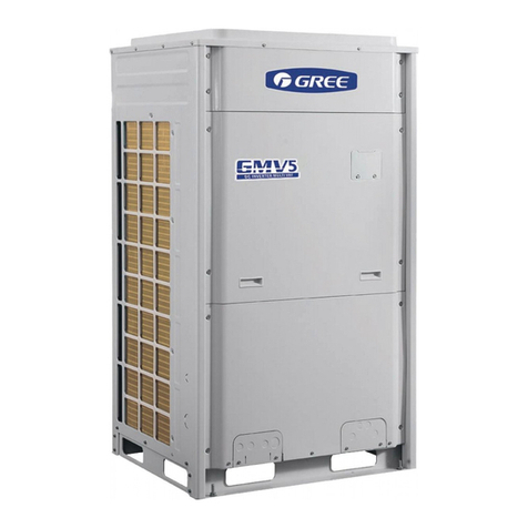
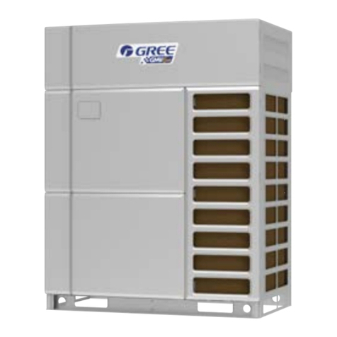
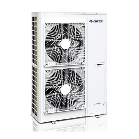
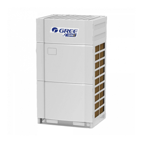
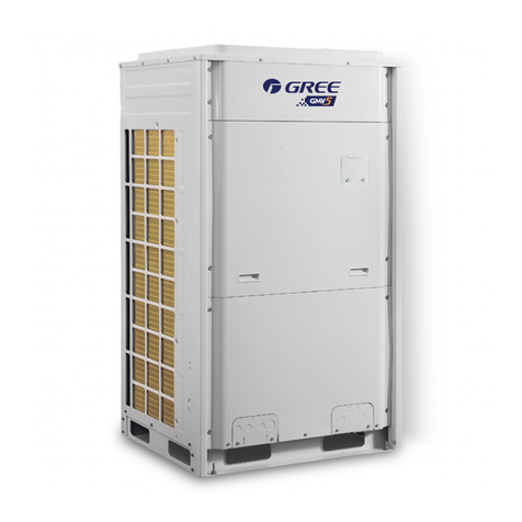
Gree GMV6 VRF User manual

Technical Sales Guide
GREE ELECTRIC APPLIANCES, INC. OF ZHUHAI
GMV6 DC INVERTER VRF UNITS
TECHNICAL SALES GUIDE-50/60Hz
CAPACITY RANGE: 22.4~246.0kW
SUPER HIGH AMBIENT OPERATION TO 55°C
(GC202005-I)

CONTENTS
1 UNIT CHARACTERISTICS �����������������������������������������������������������������������1
2 UNIT PARAMETERS ��������������������������������������������������������������������������������7
3 ELECTRICAL SPECIFICATIONS��������������������������������������������������������������14
4 PRODUCT CAPACITY RECTIFICATION ��������������������������������������������������16
5 UNIT NOISE CURVES ������������������������������������������������������������������������102
6 UNIT GRAVITY CENTER DIAGRAMS ���������������������������������������������������104
7 UNIT INSTALLATION SPACE REQUIREMENTS �������������������������������������106
8 PIPING MODEL SELECTION���������������������������������������������������������������114
9 COMMUNICATION SYSTEM INTRODUCTION������������������������������������120
10 EXTERNAL ELECTRICAL WIRING DIAGRAM���������������������������������������126
11 CALCULATION METHOD ON ADDING QUANTITY OF PIPING
REFRIGERANT���������������������������������������������������������������������������������������127
12
NOTICES������������������������������������������������������������������������������������������������������������128
13 OPTIONAL COMPONENTS��������������������������������������������������������������130

1
GMV6 DC Inverter VRF Units Technical Sales Guide
1 UNIT CHARACTERISTICS
1.1Lineup of Outdoor Unit
GMV6 DC Inverter VRF system: basic models of the full series are 8HP、10HP、12HP、14HP、16HP、
18HP、20HP and 22HP, the combination model 24HP-88HP.
HP Model Combination Mode Appearance
8GMV-224WM/H-X /
10 GMV-280WM/H-X /
12 GMV-335WM/H-X /
14 GMV-400WM/H-X /
16 GMV-450WM/H-X /
18 GMV-504WM/H-X /
20 GMV-560WM/H-X /
22 GMV-615WM/H-X /
24 GMV-680WM/H-X 280+400
26 GMV-730WM/H-X 280+450
28 GMV-784WM/H-X 280+504
30 GMV-840WM/H-X 280+560
32 GMV-895WM/H-X 280+615
34 GMV-950WM/H-X 335+615
36 GMV-1015WM/H-X 400+615
38 GMV-1065WM/H-X 450+615
40 GMV-1119WM/H-X 504+615
42 GMV-1175WM/H-X 560+615
44 GMV-1230WM/H-X 615+615
46 GMV-1290WM/H-X 280+450+560
48 GMV-1345WM/H-X 280+450+615
50 GMV-1400WM/H-X 335+450+615
52 GMV-1455WM/H-X 280+560+615
54 GMV-1510WM/H-X 280+615+615
56 GMV-1565WM/H-X 335+615+615

2
HP Model Combination Mode Appearance
58 GMV-1630WM/H-X 400+615+615
60 GMV-1680WM/H-X 450+615+615
62 GMV-1734WM/H-X 504+615+615
64 GMV-1790WM/H-X 560+615+615
66 GMV-1845WM/H-X 615+615+615
68 GMV-1905WM/H-X 280+450+560+615
70 GMV-1959WM/H-X 280+504+560+615
72 GMV-2015WM/H-X 280+560+560+615
74 GMV-2070WM/H-X 280+560+615+615
76 GMV-2125WM/H-X 280+615+615+615
78 GMV-2180WM/H-X 335+615+615+615
80 GMV-2245WM/H-X 400+615+615+615
82 GMV-2295WM/H-X 450+615+615+615
84 GMV-2349WM/H-X 504+615+615+615
86 GMV-2405WM/H-X 560+615+615+615
88 GMV-2460WM/H-X 615+615+615+615
1.2 Product Functions and Features
Gree GMV6 DC inverter multi VRF system adopts the advanced technologies such as efficient low-
temperature enthalpy-adding system, partition heat exchange flow path, subcooling design, integrated
aluminium electronic control, reliable operation control under ultra low temperature and so on, so
the unit can operate smoothly between -30 ℃~55 ℃. It provides comfortable environment for the
user no matter in severe cold or intense heat. The capacity range of GMV6 is 22.4kW ~246kW, from
8HP ~88HP, 41 models in total. Wide capacity range and flexible combination. It can be applied to the
commercial occasions like large office building, production factory or arge malls.
Compared with GMV5, GMV6 series can not only realize low temperature heating function, operation
range under low and high temperature is wider, but also has all the functions of GMV5.
Energy-efficient
Thanks to the advanced full DC inverter technology, optimized AC system design and precise intelligent
control technology.
Efficient DC inverter low temperature enthalpy-adding scroll compressor
The compressor adopts the high pressure chamber of excellent performance. It inhales directly and
reduce the overheat loss to improve compression efficiency.
Adopting the high-efficiency permanent synchronous motor, its rotor is permanent magnet, the stator is
intertwined centrally and the efficiency is higher than the normal DC inverter compressor.
Sensorless DC inverter fan motor
The DC inverter motor adopts the electromotive force to realize electrodeless speed regulation between
5Hz-90Hz. Compared with normal DC inverter motor, its operation current is smaller, input motor
power is lower and efficiency is greatly enhanced.

3
GMV6 DC Inverter VRF Units Technical Sales Guide
Leading torque control technology
It processes minimum current and maximum torue control technology
Utilize DC inverter compressor rotor magnetic resistance torque effectively, allowing the minimum
current to output the maximum torque, reducing motor winding loss and realizing higher efficiency.
Directly control the motor torque to realize ultra low speed operation of DC inverter fan motor, torque
pulsation is small, satisfying system demand while achieving comfort of higher requirement.
Quiet
Gree DC inverter multi VRF system fully considers comfort requirement, the humanized technology
upgrade the comfort perfectly. The wider operation range of the unit ensures normal operation under
severe cold or intense heat; quiet effect is better, creating a quiet working and living environment.
Quiet mode of ODU
Quiet at night
The system will memorize and judge the highest outdoor temperature. When the system is operating at
night in low load, it will enter quiet mode automatically. Based on actual application occasion, 9 kinds
of quiet mode can be set.
For example, it will enter night operation mode automatically after operating for 8h, then it enters
normal mode after 9h.
Compulsory quiet
When the unit is installed in the locations with lower noise requirement, quiet operation is necessary
no matter in the daytime or evening, at this time, you can have three kinds of compulsory quiet mode
setting to ensure that the unit is operated under low noise mode at any time. The lowest noise value is
as low as 40dB(A).
Intelligent silence
The unit can self-learn and customize user habits, and at the same time remember the user habits
characteristics. According to the user's usage characteristics and actual load matching, the output
capacity of the system can be determined automatically in the next 24 hours to achieve automatic silent
operation.
Quiet mode of IDU
IDU also adopts DC inverter motor to realize the electrodeless adjustment of speed regulation, reduce
noise value greatly, sets auto quiet mode for IDU through wired controller. Start auto quiet function
according to indoor temperature and people activity, the noise is as low as 22dB(A).
Leading technology ensures stable reliability
Gree DC inverter multi VRF system is famous in the industry with the advanced technology. After ten
years of research and experiment, the technology of DC inverter multi system is more mature. From
electrical component to mechanical assembly and control technology to communication technology,
Gree DC inverter multi VRF has been upgraded comprehensively. The continued technology innovation
will surely bring more reliable and efficient services for the user.
Oil return control technology
Gree has two exclusive oil return control technologies.
New generation of oil return control
Gree new generation of oil return control technology has implanted pressure control oil return
technology, through pressure control, it controls system oil return and oil storage status of each
compressor effectively, thus improving the service life of compressor greatly.
Exclusive oil storage technoloy of compressor
Gree DC inverter unit has exclusive compressor oil storage technology and it controls the minimum oil
level required when operating the compressor by judging the parameter.
Refrigerant storage and distribution technology
Adopt non-accumulator system circuit, reduce refrigerant charge drastically and improve system
refrigerant control precision, then store the surplus refrigerant in the pipe.

4
Balancing oil control technology
Balancing oil technology among modules
Change the defect of traditional timer oil return; it’s needless to turn off the unit to balance the oil, judge
the operation status of each module and compressor, calculate the oil reserve capacity of compressor,
adjust the operation status of compressor to realize oil balance among modules. The non-balancing oil
pipe design ensures the reliability and will not affect the capacity output of the system to maintain AC
comfort.
Oil balance technology among compressor
The refrigerant has a suction pipe in the compression working chamber of the compressor, and is
compressed and discharged into the cavity of the totally enclosed compressor, and then flows through
the refrigeration system through the exhaust pipe. According to the principle of motion fluid mechanics
and the actual amount of oil required in the working process of the compressor, the height of the oil
balance pipe is determined, the oil level of the oil pool is controlled; the minimum oil quantity required
for each compressor during operation is ensured to realize the oil balance among the compressors.
Cooling adopts the subcooling control technology to reduce cooling capacity substantially
New generation of efficient plate subcooler and condensate depression control method is adopted, the
maximum condensate depression is 35℃, AC effect is more obvious.
Unique comfort control
ODU adopts dual electronic expansion valve for adjustment, the grade of main electronic expansion
valve is 3,000 and the subcooling electronic expansion valve is 480, precisely controlling the flow of
modules in IDU and ODU.
Considering the installation characteristic (IDU type, pipe length, fall etc.), actual startup rate of IDU,
ambient indoor and outdoor temperature, diversified system startup is realized under different ambient
temperature and installation condition, the fastest startup is completed in 75s.
Humanized operation
Auto address allocation and non-polarity communication
Auto debugging and error detection
Five kinds of auto debugging function
Auto allocation of IDU and ODU address
Auto detection of IDU and ODU quantity
Auto detection of internal error of the unit
Start operation debugging automatically
Real-time judgment of pieline abnormality
The unit has three emergency functions of module, compressor and fan
The unit has two methods of recycling refrigerant
Intelligent management
Dual energy saving operation mode;
With the deepening of energy conservation and emission reduction and the stricter national
requirements to urban electricity consumption, especially in summer, the peak season of electricity
consumption, many cities will introduce corresponding power-limiting measures. Gree DC inverter multi
VRF system has two energy-saving modes for users to choose freely to meet the requirement on peak
power consumption and power-limiting.
Capacity first: If there is sufficient power supply, priority is given to meeting the capacity needs. This
mode is default factory setting.
Auto energy-saving: System will automatically adjust parameters and balance the capacity and
energy consumption according to the running state.
Forcible energy-saving: Capacity output of ODU is limited. Depending on power consumption and
user needs, a 90% or 80% capacity ratio can be selected.
Energy consumption analysis and solution
5
GMV6 DC Inverter VRF Units Technical Sales Guide
Emergency stop
Long distance monitoring is needless, ODU will introduce the fire alarm linkage signal directly, under
emergency situation, it will stop the unit for operation immediately to avoid bigger losses.
Partition management
Super-long piping distance design, the maximum length of total pipe is 1,000m
Compared with traditional screw chiller, the advantage of DC inverter multi VRF system is the easy and
convenient piping. Gree DC inverter multi VRF system is more outstanding in the aspect of actual piping,
enabling the AC system to be applied to all kinds of architecture, reducing installation cost of the user.
Cooling only system, the maximum attachable quantity of IDU is 80 sets
The attachable quantity of single system of most of the multi VRF systems in current market is 64 sets,
whiel Gree DC inverter multi VRF system is integrated with several modular unit and can connect 80
sets of IDUs at the most, which is more applicable for large commercial office buildings, apartment or
hotels.
It needs engineering custom if there are more than 80 sets and the custom is available for 100 sets at
the most.
Wide operation range
Operation range of temperature: cooling -5 ~55℃and heating -30 ~24℃.
New modular load allocation control
Choose unit module according to the operation status to realize efficient operation among modular
unit, reduce energy consumption loss and improve energy efficiency of operation, which will enhance
the reliability of the unit.
ODU high static pressure design with flexible choice
ODU will choose the corresponding static pressure according to architectural form, the maximum can
be 110Pa, especially for the occasions which need to place the ODU inside the house.

6
1.3 Nomenclature
GMV □-□ □ □ □ □ W□/□ □ □ (□)
1 2 3 4 5 6 7 8 9 10 11 12 13
No. Description Options
1Product code GMV-Gree Multi VRF Units
2Suitable climate Blank-T1 condition; T2-low temperature climate;
T3-high temperature climate
3RAC or CAC RAC-H
CAC-default
4Special function
G: high sensible heat
V: low-temperature heat pump
Default: without special function
5Unit type DC inverter-default
Y-solar power
6Function code
Q——heat recovery model, S——water heater, W——water cooled unit
X——air processing unit, Z——reheat dehumidier, Y——PV unit
G——high sensible heat unit, V——low temperature heat pump unit, XR——thermal storage
unit
No code if the above functions are missing
7Code of cooling capacity Nominal capacity/100(W)
8Code for outdoor unit W—outdoor unit
9Unit structure M—Modular (top discharge); L—Non-modular (side discharge);Default—Non-modular (top
discharge)
10 Refrigerant R410a (omit)
11 Design No. Named in order of A, B, C, or combined with 1, 2, 3…
12 Power supply 7000~18000W, 1 phase—omit; 3 phase—S
13 Special code For special area; leave blank if it is not for special area

7
GMV6 DC Inverter VRF Units Technical Sales Guide
2 UNIT PARAMETERS
Model(integrated unit) ─ ─ ─ ─
Model(single unit) GMV-224WM/H-X GMV-280WM/H-X GMV-335WM/H-X GMV-400WM/H-X
Cooling
capacity Rated kW 22.4 28 33.5 40
Heating
capacity
Rated kW 16.2 16.2 18.5 23.32
Max. kW 25 31.5 37.5 45
SEER ducted -7.7 6.85 6.55 6.89
cassette -7.36 6.2 7.2 6.74
SCOP ducted -5.51 5.51 5.74 5.15
cassette -4.75 4.75 4.84 4.44
Sound pressure level(Cooling) dB(A) 56 57 59 59
Sound power
level(Cooling)
ducted dB(A) 81 83 88 85
cassette dB(A) 81 86 88 88
Outdoor static pressure Pa 0-110 0-110 0-110 0-110
Compressor quantity set 1111
Refrigeration oil No. of
compressor -FV68H FV68H FV68H FV68H
Refrigeration
oil charge
Gross L4.6 4.6 4.6 6.1
Compressor
charge L1.1 1.1 1.1 1.1
The others L3.5 3.5 3.5 5
Power Supply 380V-415V 3N ~
50Hz/60Hz
380V-415V 3N ~
50Hz/60Hz
380V-415V 3N ~
50Hz/60Hz
380V-415V 3N ~
50Hz/60Hz
Size(W×D×H) mm 930×775×1690 930×775×1690 930×775×1690 1340×775×1690
Waterproof level IPX4 IPX4 IPX4 IPX4
Connection
pipe
Gas pipe mm Φ19.05 Φ22.2 Φ25.4 Φ25.4
Liquid pipe mm Φ9.52 Φ9.52 Φ12.7 Φ12.7
Connection method Welding connection Welding connection Welding connection Welding connection
Net weight kg 220 220 240 300
Rated power input kW 12.87 13.15 13.5 21
Rated current A23 23.5 24.1 37.5
Max. fuse current A25 25 25 40

8
Model(integrated unit) ────
Model(single unit) GMV-450WM/H-X GMV-504WM/H-X GMV-560WM/H-X GMV-615WM/H-X
Cooling
capacity Rated kW 45 50.4 56 61.5
Heating
capacity
Rated kW 23.32 31 31 33
Max. kW 50 56.5 63 69
SEER ducted -6.6 6.95 6.32 5.74
cassette -6.36 6.56 5.65 5.56
SCOP ducted -5.15 4.13 4.13 4.32
cassette -4.44 3.71 3.71 3.55
Sound pressure level(Cooling) dB(A) 60 61 62 63
Sound power
level(Cooling)
ducted dB(A) 89 93 93 93
cassette dB(A) 93 88 94 94
Outdoor static pressure Pa 0-110 0-110 0-110 0-110
Compressor quantity set 1 2 2 2
Refrigeration oil No. of
compressor -FV68H FV68H FV68H FV68H
Refrigeration
oil charge
Gross L6.1 7.2 7.2 7.2
Compressor
charge L1.1 2.2 2.2 2.2
The others L5 5 5 5
Power Supply 380V-415V 3N ~
50Hz/60Hz
380V-415V 3N ~
50Hz/60Hz
380V-415V 3N ~
50Hz/60Hz
380V-415V 3N ~
50Hz/60Hz
Size(W×D×H) mm 1340×775×1690 1340×775×1690 1340×775×1690 1340×775×1690
Waterproof level IPX4 IPX4 IPX4 IPX4
Connection
pipe
Gas pipe mm Φ28.6 Φ28.6 Φ28.6 Φ28.6
Liquid pipe mm Φ12.7 Φ15.9 Φ15.9 Φ15.9
Connection method Welding connection Welding connection Welding connection Welding connection
Net weight kg 300 350 350 355
Rated power input kW 22 26.3 26.85 27.41
Rated current A39.3 47 48 49
Max. fuse current A40 50 50 50

9
GMV6 DC Inverter VRF Units Technical Sales Guide
Model (integrated unit) GMV-680WM/H-X GMV-730WM/H-X GMV-784WM/H-X GMV-840WM/H-X
Model (single unit) GMV-280WM/H-X+
GMV-400WM/H-X
GMV-280WM/H-X+
GMV-450WM/H-X
GMV-280WM/H-X+
GMV-504WM/H-X
GMV-280WM/H-X+
GMV-560WM/H-X
Cooling
capacity Rated kW 68 73 78.4 84
Heating
capacity
Rated kW 39.52 39.52 47.2 47.2
Max. kW 76.5 81.5 88 94.5
Outdoor static pressure Pa 0-110 0-110 0-110 0-110
Power Supply 380V-415V 3N ~
50Hz/60Hz
380V-415V 3N ~
50Hz/61Hz
380V-415V 3N ~
50Hz/62Hz
380V-415V 3N ~
50Hz/63Hz
Size(W×D×H) mm 930×775×1690+
1340×775×1690
930×775×1690+
1340×775×1690
930×775×1690+
1340×775×1690
930×775×1690+
1340×775×1690
Waterproof level IPX4 IPX4 IPX4 IPX4
Connection
pipe
Gas pipe mm Φ28.6 Φ31.8 Φ31.8 Φ31.8
Liquid pipe mm Φ15.9 Φ19.05 Φ19.05 Φ19.05
Connection method Welding connection Welding connection Welding connection Welding connection
Net weight kg 220+300 220+300 220+350 220+350
Rated power input kW 13.15+21.00 13.15+22.00 13.15+26.3 13.15+26.85
Rated current A23.5+37.5 23.5+39.3 23.5+47 23.5+48
Max. fuse current A25+40 25+40 25+50 25+50
Model (integrated unit) GMV-895WM/H-X GMV-950WM/H-X GMV-1015WM/H-X GMV-1065WM/H-X
Model (single unit) GMV-280WM/H-X+
GMV-615WM/H-X
GMV-335WM/H-X+
GMV-615WM/H-X
GMV-400WM/H-X+
GMV-615WM/H-X
GMV-450WM/H-X+
GMV-615WM/H-X
Cooling
capacity Rated kW 89.5 95 101.5 106.5
Heating
capacity
Rated kW 49.2 51.5 56.32 56.32
Max. kW 100.5 106.5 114 119
Outdoor static pressure Pa 0-110 0-110 0-110 0-110
Power Supply 380V-415V 3N ~
50Hz/60Hz
380V-415V 3N ~
50Hz/61Hz
380V-415V 3N ~
50Hz/62Hz
380V-415V 3N ~
50Hz/63Hz
Size(W×D×H) mm 930×775×1690+
1340×775×1690
930×775×1690+
1340×775×1690
1340×775×1690+
1340×775×1690
1340×775×1690+
1340×775×1690
Waterproof level IPX4 IPX4 IPX4 IPX4
Connection
pipe
Gas pipe mm Φ31.8 Φ31.8 Φ31.8 Φ31.8
Liquid pipe mm Φ19.05 Φ19.05 Φ19.05 Φ19.05
Connection method Welding connection Welding connection Welding connection Welding connection
Net weight kg 220+355 240+355 300+355 300+355
Rated power input kW 13.15+27.41 13.5+27.41 21+27.41 22+27.41
Rated current A23.5+49 24.1+49 37.5+49 39.3+49
Max. fuse current A25+50 25+50 40+50 40+50

10
Model (integrated unit) GMV-1119WM/H-X GMV-1175WM/H-X GMV-1230WM/H-X GMV-1290WM/H-X
Model (single unit) GMV-504WM/H-X+
GMV-615WM/H-X
GMV-560WM/H-X+
GMV-615WM/H-X
GMV-615WM/H-X+
GMV-615WM/H-X
GMV-280WM/H-X+
GMV-450WM/H-X+
GMV-560WM/H-X
Cooling
capacity Rated kW 111.9 117.5 123 129
Heating
capacity
Rated kW 64 64 66 70.52
Max. kW 125.5 132 138 144.5
Outdoor static pressure Pa 0-110 0-110 0-110 0-110
Power Supply 380V-415V 3N ~
50Hz/60Hz
380V-415V 3N ~
50Hz/61Hz
380V-415V 3N ~
50Hz/62Hz
380V-415V 3N ~
50Hz/63Hz
Size(W×D×H) mm 1340×775×1690+
1340×775×1690
1340×775×1690+
1340×775×1690
1340×775×1690+
1340×775×1690
930×775×1690+
1340×775×1690+
1340×775×1690
Waterproof level IPX4 IPX4 IPX4 IPX4
Connection
pipe
Gas pipe mm Φ31.8 Φ31.8 Φ31.8 Φ31.8
Liquid pipe mm Φ19.05 Φ19.05 Φ19.05 Φ19.05
Connection method Welding connection Welding connection Welding connection Welding connection
Net weight kg 350+355 350+355 355+355 220+300+350
Rated power input kW 26.3+27.41 26.85+27.41 27.41+27.41 13.15+22.00+26.85
Rated current A47+49 48+49 49+49 23.5+39.3+48
Max. fuse current A50+50 50+50 50+50 25+40+50
Model (integrated unit) GMV-1345WM/H-X GMV-1400WM/H-X GMV-1455WM/H-X GMV-1510WM/H-X
Model (single unit)
GMV-280WM/H-X+
GMV-450WM/H-X+
GMV-615WM/H-X
GMV-335WM/H-X+
GMV-450WM/H-X+
GMV-615WM/H-X
GMV-280WM/H-X+
GMV-560WM/H-X+
GMV-615WM/H-X
GMV-280WM/H-X+
GMV-615WM/H-X+
GMV-615WM/H-X
Cooling
capacity Rated kW 134.5 140 145.5 151
Heating
capacity
Rated kW 72.52 74.82 80.2 82.2
Max. kW 150.5 156.5 163.5 169.5
Outdoor static pressure Pa 0-110 0-110 0-110 0-110
Power Supply 380V-415V 3N ~
50Hz/60Hz
380V-415V 3N ~
50Hz/61Hz
380V-415V 3N ~
50Hz/62Hz
380V-415V 3N ~
50Hz/63Hz
Size(W×D×H) mm
930×775×1690+
1340×775×1690+
1340×775×1690
930×775×1690+
1340×775×1690+
1340×775×1690
930×775×1690+
1340×775×1690+
1340×775×1690
930×775×1690+
1340×775×1690+
1340×775×1690
Waterproof level IPX4 IPX4 IPX4 IPX4
Connection
pipe
Gas pipe mm Φ31.8 Φ41.3 Φ41.3 Φ41.3
Liquid pipe mm Φ19.05 Φ19.05 Φ19.05 Φ19.05
Connection method Welding connection Welding connection Welding connection Welding connection
Net weight kg 220+300+355 240+300+355 220+350+355 220+355+355
Rated power input kW 13.15+22.00+27.41 13.5+22.00+27.41 13.15+26.85+27.41 13.15+27.41+27.41
Rated current A23.5+39.3+49 24.1+39.3+49 23.5+48+49 23.5+49+49
Max. fuse current A25+40+50 25+40+50 25+50+50 25+50+50

11
GMV6 DC Inverter VRF Units Technical Sales Guide
Model (integrated unit) GMV-1565WM/H-X GMV-1630WM/H-X GMV-1680WM/H-X GMV-1734WM/H-X
Model (single unit)
GMV-335WM/H-X+
GMV-615WM/H-X+
GMV-615WM/H-X
GMV-400WM/H-X+
GMV-615WM/H-X+
GMV-615WM/H-X
GMV-450WM/H-X+
GMV-615WM/H-X+
GMV-615WM/H-X
GMV-504WM/H-X+
GMV-615WM/H-X+
GMV-615WM/H-X
Cooling
capacity Rated kW 156.5 163 168 173.4
Heating
capacity
Rated kW 84.5 89.32 89.32 97
Max. kW 175.5 183 188 194.5
Outdoor static pressure Pa 0-110 0-110 0-110 0-110
Power Supply 380V-415V 3N ~
50Hz/60Hz
380V-415V 3N ~
50Hz/61Hz
380V-415V 3N ~
50Hz/62Hz
380V-415V 3N ~
50Hz/63Hz
Size(W×D×H) mm
930×775×1690+
1340×775×1690+
1340×775×1690
1340×775×1690+
1340×775×1690+
1340×775×1690
1340×775×1690+
1340×775×1690+
1340×775×1690
1340×775×1690+
1340×775×1690+
1340×775×1690
Waterproof level IPX4 IPX4 IPX4 IPX4
Connection
pipe
Gas pipe mm Φ41.3 Φ41.3 Φ41.3 Φ41.3
Liquid pipe mm Φ19.05 Φ19.05 Φ19.05 Φ19.05
Connection method Welding connection Welding connection Welding connection Welding connection
Net weight kg 240+355+355 300+355+355 300+355+355 350+355+355
Rated power input kW 13.5+27.41+27.41 21+27.41+27.41 22+27.41+27.41 26.3+27.41+27.41
Rated current A24.1+49+49 37.5+49+49 39.3+49+49 47+49+49
Max. fuse current A25+50+50 40+50+50 40+50+50 50+50+50
Model (integrated unit) GMV-1790WM/H-X GMV-1845WM/H-X GMV-1905WM/H-X GMV-1959WM/H-X
Model (single unit)
GMV-560WM/H-X+
GMV-615WM/H-X+
GMV-615WM/H-X+
GMV-615WM/H-X+
GMV-615WM/H-X+
GMV-615WM/H-X+
GMV-280WM/H-X+
GMV-450WM/H-X+
GMV-560WM/H-X+
GMV-615WM/H-X
GMV-280WM/H-X+
GMV-504WM/H-X+
GMV-560WM/H-X+
GMV-615WM/H-X
Cooling
capacity Rated kW 179 184.5 190.5 195.9
Heating
capacity
Rated kW 97 99 103.52 111.2
Max. kW 201 207 213.5 220
Outdoor static pressure Pa 0-110 0-110 0-110 0-110
Power Supply 380V-415V 3N ~
50Hz/60Hz
380V-415V 3N ~
50Hz/61Hz
380V-415V 3N ~
50Hz/62Hz
380V-415V 3N ~
50Hz/63Hz
Size(W×D×H) mm
1340×775×1690+
1340×775×1690+
1340×775×1690
1340×775×1690+
1340×775×1690+
1340×775×1690
930×775×1690+
1340×775×1690+
1340×775×1690
930×775×1690+
1340×775×1690+
1340×775×1690
Waterproof level IPX4 IPX4 IPX4 IPX4
Connection
pipe
Gas pipe mm Φ41.3 Φ41.3 Φ44.5 Φ44.5
Liquid pipe mm Φ19.05 Φ19.05 Φ22.2 Φ22.2
Connection method Welding connection Welding connection Welding connection Welding connection
Net weight kg 350+355+355 355+355+355 220+300+
350+355
220++350+
350+355
Rated power input kW 26.85+27.41+27.41 27.41+27.41+27.41 13.15+22.00+
26.85+27.41
13.15+26.3+
26.85+27.41
Rated current A48+49+49 49+49+49 23.5+39.3+48+49 23.5++47+48+49
Max. fuse current A50+50+50 50+50+50 25+40+50+50 25+50+50+50

12
Model (integrated unit) GMV-2015WM/H-X GMV-2070WM/H-X GMV-2125WM/H-X GMV-2180WM/H-X
Model (single unit)
GMV-280WM/H-X+
GMV-560WM/H-X+
GMV-560WM/H-X+
GMV-615WM/H-X
GMV-280WM/H-X+
GMV-560WM/H-X+
GMV-615WM/H-X+
GMV-615WM/H-X
GMV-280WM/H-X+
GMV-615WM/H-X+
GMV-615WM/H-X+
GMV-615WM/H-X
GMV-335WM/H-X+
GMV-615WM/H-X+
GMV-615WM/H-X+
GMV-615WM/H-X
Cooling
capacity Rated kW 201.5 207 212.5 218
Heating
capacity
Rated kW 111.2 113.2 115.2 117.5
Max. kW 226.5 232.5 238.5 244.5
Outdoor static pressure Pa 0-110 0-110 0-110 0-110
Power Supply 380V-415V 3N ~
50Hz/60Hz
380V-415V 3N ~
50Hz/61Hz
380V-415V 3N ~
50Hz/62Hz
380V-415V 3N ~
50Hz/63Hz
Size(W×D×H) mm
930×775×1690+
1340×775×1690+
1340×775×1690+
1340×775×1690
930×775×1690+
1340×775×1690+
1340×775×1690+
1340×775×1690
930×775×1690+
1340×775×1690+
1340×775×1690+
1340×775×1690
930×775×1690+
1340×775×1690+
1340×775×1690+
1340×775×1690
Waterproof level IPX4 IPX4 IPX4 IPX4
Connection
pipe
Gas pipe mm Φ44.5 Φ44.5 Φ44.5 Φ44.5
Liquid pipe mm Φ22.2 Φ22.2 Φ22.2 Φ22.2
Connection method Welding connection Welding connection Welding connection Welding connection
Net weight kg 220+350+
350+355
220+350+
355+355
220+355+
355+355
240+355+
355+355
Rated power input kW 13.15+26.85+
26.85+27.41
13.15+26.85+
27.41+27.41
13.15+27.41+
27.41+27.41
13.5+27.41+
27.41+27.41
Rated current A23.5+48+
48+49
23.5+48+
49+49
23.5+49+
49+49
24.1+49+
49+49
Max. fuse current A25+50+
50+50
25+50+
50+50
25+50+
50+50
25+50+
50+50
Model (integrated unit)
GMV-2245WM/H-X GMV-2295WM/H-X GMV-2349WM/H-X GMV-2405WM/H-X GMV-2460WM/H-X
Model (single unit)
GMV-400WM/H-X+
GMV-615WM/H-X+
GMV-615WM/H-X+
GMV-615WM/H-X
GMV-450WM/H-X+
GMV-615WM/H-X+
GMV-615WM/H-X+
GMV-615WM/H-X
GMV-504WM/H-X+
GMV-615WM/H-X+
GMV-615WM/H-X+
GMV-615WM/H-X
GMV-560WM/H-X+
GMV-615WM/H-X+
GMV-615WM/H-X+
GMV-615WM/H-X
GMV-615WM/H-X+
GMV-615WM/H-X+
GMV-615WM/H-X+
GMV-615WM/H-X
Cooling
capacity Rated kW 224.5 229.5 234.9 204.5 246
Heating
capacity
Rated kW 122.32 122.32 130 130 132
Max. kW 252 257 263.5 270 276
Outdoor static pressure Pa 0-110 0-110 0-110 0-110 0-110
Power Supply 380V-415V 3N ~
50Hz/60Hz
380V-415V 3N ~
50Hz/61Hz
380V-415V 3N ~
50Hz/62Hz
380V-415V 3N ~
50Hz/63Hz
380V-415V 3N ~
50Hz/60Hz
Heating
power input
Rated kW 10.75+16.1+
16.1+16.1
10.75+16.1+
16.1+16.1
14.76+16.1+
16.1+16.1
14.76+16.1+
16.1+16.1
16.1+16.1+
16.1+16.1
Max. kW 11.61+24.27+
24.27+24.27
14.51+24.27+
24.27+24.27
16.58+24.27+
24.27+24.27
21.09+24.27+
24.27+24.27
11.61+24.27+
24.27+24.27
Size(W×D×H) mm
1340×775×1690+
1340×775×1690+
1340×775×1690+
1340×775×1690
1340×775×1690+
1340×775×1690+
1340×775×1690+
1340×775×1690
1340×775×1690+
1340×775×1690+
1340×775×1690+
1340×775×1690
1340×775×1690+
1340×775×1690+
1340×775×1690+
1340×775×1690
1340×775×1690+
1340×775×1690+
1340×775×1690+
1340×775×1690
Waterproof level IPX4 IPX4 IPX4 IPX4 IPX4
Connection
pipe
Gas pipe mm Φ44.5 Φ44.5 Φ44.5 Φ44.5 Φ44.5
Liquid
pipe mm Φ22.2 Φ22.2 Φ22.2 Φ22.2 Φ22.2
Connection
method
Welding
connection
Welding
connection
Welding
connection
Welding
connection
Welding
connection
Net weight kg 300+355+
355+355
300+355+
355+355
350+355+
355+355
350+355+
355+355
355+355+
355+355

13
GMV6 DC Inverter VRF Units Technical Sales Guide
Model (integrated unit)
GMV-2245WM/H-X GMV-2295WM/H-X GMV-2349WM/H-X GMV-2405WM/H-X GMV-2460WM/H-X
Model (single unit)
GMV-400WM/H-X+
GMV-615WM/H-X+
GMV-615WM/H-X+
GMV-615WM/H-X
GMV-450WM/H-X+
GMV-615WM/H-X+
GMV-615WM/H-X+
GMV-615WM/H-X
GMV-504WM/H-X+
GMV-615WM/H-X+
GMV-615WM/H-X+
GMV-615WM/H-X
GMV-560WM/H-X+
GMV-615WM/H-X+
GMV-615WM/H-X+
GMV-615WM/H-X
GMV-615WM/H-X+
GMV-615WM/H-X+
GMV-615WM/H-X+
GMV-615WM/H-X
Rated power input kW 21+27.41+
27.41+27.41
22+27.41+
27.41+27.41
26.3+27.41+
27.41+27.41
26.85+27.41+
27.41+27.41
27.41+27.41+
27.41+27.41
Rated current A37.5+49+
49+49
39.3+49+
49+49
47+49+
49+49
48+49+
49+49
49+49+
49+49
Max. fuse current A40+50+
50+50
40+50+
50+50
50+50+
50+50
50+50+
50+50
50+50+
50+50
NOTES:
a. Rated cooling capacity test conditions: indoor 27℃DB/19℃WB, outdoor 35℃DB; connection pipe
length: 5 m, without height drop between units.
b. Rated heating capacity test conditions(Tdesingnh): indoor 20℃DB, outdoor -10℃DB/-11 ℃WB;
connection pipe length: 5 m, without height drop between units. Max heating capacity test conditions:
indoor 20℃DB, outdoor 7℃DB/6 ℃WB; connection pipe length: 5 m, without height drop between
units.
c. The total capacity of connected indoor units must be in the range of 50%~135% of the outdoor unit
capacity. The relevant parameters can be corrected by referring to the unit capacity correction table.
d. The above parameters are tested based on the standard connection pipe length. In the actual project,
the parameters should be corrected referring to the capacity correction for the long connection pipe of
units.
e. Specifications may be changed due to product improvement. Please refer to nameplates of the units.

14
3 ELECTRICAL SPECIFICATIONS
Model Combination method Power supply
Capacity of
circuit breaker of
each combination
module (A)
Minimum cross-
sectional area of
grounding wire (mm2)
Recommended wire
(cross-sectional area)
(mm2)
GMV-224WM/H-X -380-415V 3N~
50/60Hz 25 2.5 2.5×5
GMV-280WM/H-X -380-415V 3N~
50/60Hz 25 2.5 2.5×5
GMV-335WM/H-X -380-415V 3N~
50/60Hz 25 4.0 4.0×5
GMV-400WM/H-X -380-415V 3N~
50/60Hz 40 6.0 6.0×5
GMV-450WM/H-X -380-415V 3N~
50/60Hz 40 6.0 6.0×5
GMV-504WM/H-X -380-415V 3N~
50/60Hz 50 10.0 10.0×5
GMV-560WM/H-X -380-415V 3N~
50/60Hz 50 10.0 10.0×5
GMV-615WM/H-X -380-415V 3N~
50/60Hz 50 10.0 10.0×5
GMV-680WM/H-X 280+400 380-415V 3N~
50/60Hz 25+40 2.5+6.0 2.5×5+6.0×5
GMV-730WM/H-X 280+450 380-415V 3N~
50/60Hz 25+40 2.5+6.0 2.5×5+6.0×5
GMV-784WM/H-X 280+504 380-415V 3N~
50/60Hz 25+50 2.5+10.0 2.5×5+10.0×5
GMV-840WM/H-X 280+560 380-415V 3N~
50/60Hz 25+50 2.5+10.0 2.5×5+10.0×5
GMV-895WM/H-X 280+615 380-415V 3N~
50/60Hz 25+50 2.5+10.0 2.5×5+10.0×5
GMV-950WM/H-X 335+615 380-415V 3N~
50/60Hz 25+50 4.0+10.0 4.0×5+10.0×5
GMV-1015WM/H-X 400+615 380-415V 3N~
50/60Hz 40+50 6.0+10.0 6.0×5+10.0×5
GMV-1065WM/H-X 450+615 380-415V 3N~
50/60Hz 40+50 6.0+10.0 6.0×5+10.0×5
GMV-1119WM/H-X 504+615 380-415V 3N~
50/60Hz 50+50 10.0+10.0 10.0×5+10.0×5
GMV-1175WM/H-X 560+615 380-415V 3N~
50/60Hz 50+50 10.0+10.0 10.0×5+10.0×5
GMV-1230WM/H-X 615+615 380-415V 3N~
50/60Hz 50+50 10.0+10.0 10.0×5+10.0×5
GMV-1290WM/H-X 280+450+560 380-415V 3N~
50/60Hz 25+40+50 2.5+6.0+10.0 2.5×5+6.0×5+10.0×5
GMV-1345WM/H-X 280+450+615 380-415V 3N~
50/60Hz 25+40+50 2.5+6.0+10.0 2.5×5+6.0×5+10.0×5
GMV-1400WM/H-X 335+450+615 380-415V 3N~
50/60Hz 25+40+50 4.0+6.0+10.0 4.0×5+6.0×5+10.0×5
GMV-1455WM/H-X 280+560+615 380-415V 3N~
50/60Hz 25+50+50 2.5+10.0+10.0 2.5×5+10.0×5+10.0×5
GMV-1510WM/H-X 280+615+615 380-415V 3N~
50/60Hz 25+50+50 2.5+10.0+10.0 2.5×5+10.0×5+10.0×5
GMV-1565WM/H-X 335+615+615 380-415V 3N~
50/60Hz 25+50+50 4.0+10.0+10.0 4.0×5+10.0×5+10.0×5
GMV-1630WM/H-X 400+615+615 380-415V 3N~
50/60Hz 40+50+50 6.0+10.0+10.0 6.0×5+10.0×5+10.0×5
GMV-1680WM/H-X 450+615+615 380-415V 3N~
50/60Hz 40+50+50 6.0+10.0+10.0 6.0×5+10.0×5+10.0×5
GMV-1734WM/H-X 504+615+615 380-415V 3N~
50/60Hz 50+50+50 10.0+10.0+10.0 10.0×5+10.0×5+10.0×5
GMV-1790WM/H-X 560+615+615 380-415V 3N~
50/60Hz 50+50+50 10.0+10.0+10.0 10.0×5+10.0×5+10.0×5
GMV-1845WM/H-X 615+615+615 380-415V 3N~
50/60Hz 50+50+50 10.0+10.0+10.0 10.0×5+10.0×5+10.0×5
GMV-1905WM/H-X 280+450+560+615 380-415V 3N~
50/60Hz 25+40+50+50 2.5+6.0+10.0+10.0 2.5×5+6.0×5+
10.0×5+10.0×5

15
GMV6 DC Inverter VRF Units Technical Sales Guide
Model Combination method Power supply
Capacity of
circuit breaker of
each combination
module (A)
Minimum cross-
sectional area of
grounding wire (mm2)
Recommended wire
(cross-sectional area)
(mm2)
GMV-1959WM/H-X 280+504+560+615 380-415V 3N~
50/60Hz 25+50+50+50 2.5+10.0+10.0+10.0 2.5×5+10.0×5+
10.0×5+10.0×5
GMV-2015WM/H-X 280+560+560+615 380-415V 3N~
50/60Hz 25+50+50+50 2.5+10.0+10.0+10.0 2.5×5+10.0×5+
10.0×5+10.0×5
GMV-2070WM/H-X 280+560+615+615 380-415V 3N~
50/60Hz 25+50+50+50 2.5+10.0+10.0+10.0 2.5×5+10.0×5+
10.0×5+10.0×5
GMV-2125WM/H-X 280+615+615+615 380-415V 3N~
50/60Hz 25+50+50+50 2.5+10.0+10.0+10.0 2.5×5+10.0×5+
10.0×5+10.0×5
GMV-2180WM/H-X 335+615+615+615 380-415V 3N~
50/60Hz 25+50+50+50 4.0+10.0+10.0+10.0 4.0×5+10.0×5+
10.0×5+10.0×5
GMV-2245WM/H-X 400+615+615+615 380-415V 3N~
50/60Hz 40+50+50+50 6.0+10.0+10.0+10.0 6.0×5+10.0×5+
10.0×5+10.0×5
GMV-2295WM/H-X 450+615+615+615 380-415V 3N~
50/60Hz 40+50+50+50 6.0+10.0+10.0+10.0 6.0×5+10.0×5+
10.0×5+10.0×5
GMV-2349WM/H-X 504+615+615+615 380-415V 3N~
50/60Hz 50+50+50+50 10.0+10.0+10.0+10.0 10.0×5+10.0×5+
10.0×5+10.0×5
GMV-2405WM/H-X 560+615+615+615 380-415V 3N~
50/60Hz 50+50+50+50 10.0+10.0+10.0+10.0 10.0×5+10.0×5+
10.0×5+10.0×5
GMV-2460WM/H-X 615+615+615+615 380-415V 3N~
50/60Hz 50+50+50+50 10.0+10.0+10.0+10.0 10.0×5+10.0×5+
10.0×5+10.0×5
NOTES:
a. The circuit breaker and power cable specifications are selected according to the maximum unit power
(maximum current).
b. The power cable specifications are obtained under the condition that the multi-copper core cable
(such as YJV copper-core XLPE insulated PVC sheathed power cable) is laid in the wire trough in an
exposed manner (the ambient temperature of use is 40℃and the cable operating temperature is 90℃)
(IEC60364-5-523). If the use condition is different, calculate and adjust the specification according to
the corresponding national standard.
c. The copper core cable must be used.
d. The engineering wiring should meet the requirements of IEC 60364-5-52 to ensure that the line
voltage drop meets the requirements and the voltage is not lower than the lower limit of the nominal
value of equipment.
e. The circuit breaker specification is obtained under the condition that the ambient temperature is
40 ℃when the circuit breaker is operating. If the use condition is different, calculate and adjust the
specification according to the instructions on circuit breaker specifications.
f. The circuit breaker should provide the magnetic trip and thermal trip functions at the same time to
ensure protection in the cases of short circuit and overload.

16
4 PRODUCT CAPACITY RECTIFICATION
4.1Capacity rectification method for IDU and ODU
Actual capacity of each IDU=Actual capacity of ODU×IDU capacity/Max. IDU capacity operating at the
same time
Actual capacity of ODU=Rectified capacity based on the configuration rate of IDU and ODU and the
indoor and outside temperature condition×pipe distance and the rectification coefficient of fall of IDU
and ODU×rectification factor of heating and defrosting
NOTES:
a. Rectified capacity based on the configuration rate of IDU and ODU and the indoor and outside
temperature condition——inquire according to the capacity rectification table.
b. Rectification factor of heating and defrosting——rectify the factor if the model selection is based on
heating load.
4.3 Correction of capacity along with ambient temperature and
configuration ratio
Rectification of cooling capacity:
GMV-224WM/H-X
TC—Total capacity of outdoor unit; PI—Power input of outdoor unit
Combination
Outdoor air
temp
(
℃DB
)
Indoor air temp
14.0℃WB 16.0℃WB 18.0℃WB 19.0℃WB 20.0℃WB 22.0℃WB 24.0℃WB
20.0℃DB 23.0℃DB 26.0℃DB 27.0℃DB 28.0℃DB 30.0℃DB 32.0℃DB
TC PI TC PI TC PI TC PI TC PI TC PI TC PI
kW kW kW kW kW kW kW kW kW kW kW kW kW kW
135%
-5 19.8 2.91 23.6 3.55 27.4 3.59 28.4 3.61 29.0 3.63 29.7 3.67 30.4 3.71
019.8 2.92 23.6 3.55 27.4 3.60 28.4 3.62 29.0 3.64 29.7 3.68 30.4 3.72
419.8 2.93 23.6 3.57 27.4 3.61 28.4 3.63 29.0 3.65 29.7 3.69 30.4 3.73
719.8 2.98 23.6 3.63 27.4 3.68 28.4 3.70 29.0 3.72 29.7 3.76 30.4 3.80
10 19.8 3.04 23.6 3.71 27.4 4.41 28.4 4.51 28.8 4.42 29.5 4.24 30.2 4.04
12 19.8 3.09 23.6 3.78 27.4 4.50 28.0 4.48 28.4 4.40 29.1 4.20 29.8 4.14
14 19.8 3.15 23.6 3.85 27.3 4.56 27.7 4.47 28.0 4.37 28.8 4.33 29.5 4.38
16 19.8 3.21 23.6 3.93 27.0 4.54 27.3 4.50 27.6 4.52 28.4 4.56 29.1 4.61
18 19.8 3.27 23.6 4.01 26.6 4.71 26.9 4.73 27.3 4.76 28.0 4.80 28.8 4.85
20 19.8 3.34 23.6 4.27 26.2 4.94 26.6 4.96 26.9 4.99 27.6 5.04 28.4 5.09
21 19.8 3.43 23.6 4.42 26.0 5.05 26.4 5.08 26.7 5.11 27.5 5.16 28.2 5.20
23 19.8 3.68 23.6 4.74 25.7 5.28 26.0 5.31 26.3 5.34 27.1 5.39 27.8 5.44
25 19.8 3.93 23.6 5.08 25.3 5.52 25.7 5.54 26.0 5.58 26.7 5.63 27.5 5.68
27 19.8 4.19 23.6 5.44 25.0 4.86 25.3 5.78 25.6 5.81 26.3 5.87 27.1 5.93
29 19.8 4.48 23.6 5.81 24.6 5.98 24.9 6.01 25.3 6.05 26.0 6.11 26.7 6.17
31 19.8 4.78 23.5 6.15 24.2 6.22 24.6 6.25 24.9 6.28 25.6 6.35 26.3 6.42
33 19.8 5.09 23.1 6.38 23.8 6.44 24.2 6.48 24.6 6.52 25.3 6.59 25.9 6.67
35 19.8 5.43 22.7 6.61 23.4 6.69 23.8 6.72 24.2 6.76 24.9 6.84 25.6 6.91
37 19.8 5.77 22.4 6.85 23.1 6.93 23.4 6.96 23.8 7.01 24.5 7.09 25.2 7.17
39 19.8 6.15 22.0 7.08 22.7 7.16 23.1 7.20 23.4 7.25 24.2 7.33 24.9 7.42
41 18.7 6.84 21.6 8.33 22.3 8.43 22.7 7.80 23.0 7.84 23.7 7.93 24.4 8.01
43 17.7 7.13 21.2 8.68 21.8 8.88 22.2 8.29 22.5 8.14 23.2 8.13 23.9 8.22
44 17.4 7.43 20.4 9.05 21.2 9.36 21.7 8.81 22.1 8.45 22.8 8.34 23.6 8.43
47 16.4 9.89 19.8 12.05 20.5 9.83 20.9 8.94 21.3 8.99 22.0 8.96 22.8 9.05
50 15.1 9.71 17.7 11.83 18.3 10.37 18.7 9.68 19.0 9.60 19.7 9.57 20.5 9.47
52 9.6 5.75 12.9 7.16 16.0 8.05 17.6 8.46 17.7 8.18 18.1 8.07 19.2 8.28

17
GMV6 DC Inverter VRF Units Technical Sales Guide
TC—Total capacity of outdoor unit; PI—Power input of outdoor unit
Combination
Outdoor air
temp
(
℃DB
)
Indoor air temp
14.0℃WB 16.0℃WB 18.0℃WB 19.0℃WB 20.0℃WB 22.0℃WB 24.0℃WB
20.0℃DB 23.0℃DB 26.0℃DB 27.0℃DB 28.0℃DB 30.0℃DB 32.0℃DB
TC PI TC PI TC PI TC PI TC PI TC PI TC PI
kW kW kW kW kW kW kW kW kW kW kW kW kW kW
120%
-5 18.3 2.59 21.8 3.36 25.3 3.57 27.1 3.59 28.5 3.61 29.1 3.64 29.8 3.68
018.3 2.60 21.8 3.36 25.3 3.57 27.1 3.59 28.5 3.61 29.1 3.65 29.8 3.69
418.3 2.61 21.8 3.38 25.3 3.59 27.1 3.61 28.5 3.63 29.1 3.66 29.8 3.70
718.3 2.66 21.8 3.44 25.3 3.65 27.1 3.67 28.5 3.69 29.1 3.73 29.8 3.77
10 18.3 2.77 21.8 3.38 25.3 4.02 27.1 4.35 28.4 4.54 29.0 4.36 29.6 4.19
12 18.3 2.82 21.8 3.45 25.3 4.10 27.1 4.43 28.0 4.51 28.6 4.34 29.2 4.17
14 18.3 2.88 21.8 3.52 25.3 4.18 27.1 4.52 27.6 4.48 28.3 4.32 28.9 4.34
16 18.3 2.93 21.8 3.59 25.3 4.26 26.9 4.56 27.2 4.49 27.9 4.54 28.5 4.57
18 18.3 2.98 21.8 3.66 25.3 4.41 26.5 4.71 26.8 4.72 27.5 4.77 28.2 4.81
20 18.3 3.05 21.8 3.80 25.3 4.74 26.2 4.94 26.5 4.96 27.1 5.00 27.8 5.04
21 18.3 3.07 21.8 3.93 25.3 4.91 25.9 5.05 26.3 5.07 27.0 5.12 27.6 5.17
23 18.3 3.29 21.8 4.22 25.3 5.26 25.6 5.28 25.9 5.30 26.6 5.36 27.2 5.40
25 18.3 3.51 21.8 4.51 24.9 5.49 25.2 5.51 25.5 5.53 26.3 5.59 26.9 5.64
27 18.3 3.75 21.8 4.82 24.6 5.71 24.9 5.75 25.2 5.77 25.9 5.83 26.5 5.88
29 18.3 4.00 21.8 5.15 24.2 5.94 24.5 5.98 24.8 6.00 25.5 6.07 26.2 6.12
31 18.3 4.26 21.8 5.50 23.8 6.18 24.2 6.21 24.5 6.24 25.1 6.31 25.8 6.37
33 18.3 4.54 21.8 5.87 23.4 6.41 23.8 6.45 24.1 6.47 24.7 6.55 25.4 6.61
35 18.3 4.83 21.8 6.25 23.0 6.64 23.4 6.68 23.8 6.71 24.4 6.79 25.1 6.86
37 18.3 5.14 21.8 6.66 22.7 6.88 23.0 6.92 23.4 6.95 24.0 7.02 24.7 7.10
39 18.3 5.47 21.7 7.03 22.3 7.11 22.6 7.16 23.0 7.19 23.7 7.27 24.3 7.34
41 17.3 6.09 20.7 7.88 21.9 8.37 22.2 7.75 22.6 7.79 23.2 7.87 23.9 7.95
43 16.3 6.34 19.7 8.21 21.5 8.82 21.8 8.23 22.2 8.08 22.8 8.07 23.4 8.16
44 16.1 6.62 19.6 8.57 20.9 9.30 21.3 8.75 21.7 8.39 22.4 8.28 23.0 8.36
47 15.2 8.81 18.9 11.40 20.2 9.77 20.5 8.88 20.9 8.93 21.6 8.89 22.3 8.98
50 13.9 8.65 17.0 11.19 18.0 10.30 18.3 9.62 18.7 9.53 19.3 9.50 20.0 9.39
52 9.4 5.71 12.7 7.11 15.7 8.00 17.3 8.40 17.4 8.12 17.8 8.01 18.8 8.23
110%
-5 16.8 2.29 20.0 2.95 23.2 3.54 24.8 3.56 26.4 3.58 28.5 3.61 29.1 3.65
016.8 2.30 20.0 2.96 23.2 3.55 24.8 3.57 26.4 3.59 28.5 3.62 29.1 3.66
416.8 2.31 20.0 2.97 23.2 3.56 24.8 3.58 26.4 3.60 28.5 3.64 29.1 3.67
716.8 2.35 20.0 3.02 23.2 3.63 24.8 3.65 26.4 3.67 28.5 3.70 29.1 3.74
10 16.8 2.51 20.0 3.06 23.2 3.64 24.8 3.93 26.4 4.24 28.4 4.49 29.1 4.34
12 16.8 2.57 20.0 3.13 23.2 3.71 24.8 4.01 26.4 4.32 28.1 4.48 28.7 4.32
14 16.8 2.61 20.0 3.18 23.2 3.78 24.8 4.09 26.4 4.40 27.7 4.48 28.4 4.31
16 16.8 2.66 20.0 3.24 23.2 3.85 24.8 4.17 26.4 4.48 27.4 4.50 28.0 4.55
18 16.8 2.71 20.0 3.30 23.2 3.93 24.8 4.28 26.4 4.70 27.0 4.73 27.6 4.78
20 16.8 2.76 20.0 3.37 23.2 4.17 24.8 4.60 26.0 4.93 26.7 4.96 27.2 5.01
21 16.8 2.79 20.0 3.47 23.2 4.32 24.8 4.77 25.9 5.04 26.4 5.08 27.1 5.12
23 16.8 2.92 20.0 3.72 23.2 4.63 24.8 5.12 25.5 5.27 26.1 5.32 26.7 5.36
25 16.8 3.11 20.0 3.98 23.2 4.95 24.8 5.48 25.1 5.50 25.7 5.55 26.3 5.60
27 16.8 3.32 20.0 4.25 23.2 5.29 24.4 5.71 24.7 5.73 25.4 5.78 25.9 5.83
29 16.8 3.54 20.0 4.54 23.2 5.66 24.1 5.94 24.4 5.97 25.0 6.02 25.6 6.07
31 16.8 3.77 20.0 4.84 23.2 6.04 23.7 6.17 24.0 6.20 24.7 6.25 25.2 6.31
33 16.8 4.01 20.0 5.16 23.0 6.37 23.4 6.40 23.7 6.43 24.2 6.49 24.9 6.55
35 16.8 4.27 20.0 5.50 22.7 6.60 23.0 6.63 23.3 6.67 23.8 6.73 24.5 6.79
37 16.8 4.55 20.0 5.85 22.3 6.84 22.6 6.87 22.9 6.90 23.5 6.97 24.1 7.03
39 16.8 4.83 20.0 6.23 21.9 7.07 22.2 7.10 22.6 7.14 23.1 7.21 23.8 7.28
41 15.8 5.38 19.0 6.93 21.6 8.31 21.8 7.70 22.1 7.74 22.7 7.81 23.3 7.88
43 15.0 5.61 18.0 7.22 21.3 8.76 21.4 8.18 21.7 8.03 22.3 8.01 22.9 8.08
44 14.7 5.85 18.0 7.53 20.6 9.24 20.9 8.69 21.3 8.34 21.8 8.21 22.5 8.29
47 13.9 7.79 17.4 10.02 19.9 9.70 20.2 8.82 20.5 8.87 21.1 8.82 21.8 8.90
50 12.7 7.65 15.6 9.84 17.7 10.23 18.0 9.55 18.3 9.47 18.8 9.42 19.6 9.31
52 9.3 5.67 12.5 7.06 15.4 7.95 17.0 8.34 17.1 8.07 17.5 7.96 18.4 8.17

18
TC—Total capacity of outdoor unit; PI—Power input of outdoor unit
Combination
Outdoor air
temp
(
℃DB
)
Indoor air temp
14.0℃WB 16.0℃WB 18.0℃WB 19.0℃WB 20.0℃WB 22.0℃WB 24.0℃WB
20.0℃DB 23.0℃DB 26.0℃DB 27.0℃DB 28.0℃DB 30.0℃DB 32.0℃DB
TC PI TC PI TC PI TC PI TC PI TC PI TC PI
kW kW kW kW kW kW kW kW kW kW kW kW kW kW
100%
-5 15.2 2.01 18.1 2.57 21.1 3.20 22.4 3.54 24.0 3.56 27.0 3.59 28.5 3.62
015.2 2.01 18.1 2.57 21.1 3.21 22.4 3.55 24.0 3.56 27.0 3.60 28.5 3.63
415.2 2.02 18.1 2.58 21.1 3.22 22.4 3.56 24.0 3.58 27.0 3.61 28.5 3.64
715.2 2.05 18.1 2.63 21.1 3.28 22.4 3.62 24.0 3.64 27.0 3.68 28.5 3.71
10 15.2 2.27 18.1 2.76 21.1 3.27 22.4 3.53 24.0 3.81 27.0 4.31 28.5 4.48
12 15.2 2.30 18.1 2.80 21.1 3.31 22.4 3.57 24.0 3.88 27.0 4.39 28.1 4.44
14 15.2 2.34 18.1 2.85 21.1 3.37 22.4 3.64 24.0 3.95 27.0 4.46 27.8 4.41
16 15.2 2.40 18.1 2.91 21.1 3.44 22.4 3.72 24.0 4.04 26.9 4.56 27.4 4.51
18 15.2 2.45 18.1 2.98 21.1 3.51 22.4 3.79 24.0 4.12 26.5 4.65 27.1 4.72
20 15.2 2.49 18.1 3.02 21.1 3.63 22.4 3.99 24.0 4.38 26.1 4.89 26.7 4.97
21 15.2 2.51 18.1 3.05 21.1 3.75 22.4 4.13 24.0 4.53 25.9 5.06 26.5 5.11
23 15.2 2.58 18.1 3.26 21.1 4.03 22.4 4.44 24.0 4.88 25.6 5.36 26.1 5.40
25 15.2 2.74 18.1 3.47 21.1 4.29 22.4 4.72 24.0 5.21 25.2 5.55 25.8 5.60
27 15.2 2.93 18.1 3.71 21.1 4.60 22.4 5.07 24.0 5.59 24.8 5.75 25.4 5.80
29 15.2 3.10 18.1 3.96 21.1 4.92 22.4 5.42 23.9 5.93 24.5 6.02 25.0 6.08
31 15.2 3.30 18.1 4.22 21.1 5.25 22.4 5.84 23.6 6.17 23.9 6.27 24.7 6.32
33 15.2 3.51 18.1 4.49 21.1 5.59 22.4 6.18 23.2 6.39 23.8 6.45 24.3 6.51
35 15.2 3.74 18.1 4.78 21.1 5.96 22.4 6.59 22.8 6.62 23.3 6.68 23.9 6.74
37 15.2 3.98 18.1 5.09 21.1 6.35 22.2 6.83 22.5 6.86 23.0 6.91 23.6 6.97
39 15.2 4.24 18.1 5.42 21.1 6.76 21.9 7.05 22.0 7.09 22.7 7.14 23.0 7.20
41 14.4 4.71 17.2 6.03 20.1 7.51 21.4 7.64 21.7 7.68 22.2 7.75 22.8 7.82
43 13.6 4.91 16.4 6.29 19.6 7.92 21.0 8.12 21.4 7.97 21.7 7.95 22.6 8.02
44 13.4 5.12 16.3 6.55 19.1 8.35 20.5 8.63 20.8 8.28 21.4 8.15 22.0 8.23
47 12.6 6.81 15.8 8.72 18.5 8.77 19.8 8.76 20.1 8.81 20.7 8.75 21.3 8.83
50 11.6 6.69 14.1 8.56 16.5 9.24 17.7 9.49 17.9 9.40 18.4 9.36 19.1 9.24
52 9.1 5.16 12.2 6.43 15.1 7.23 16.7 7.60 16.8 7.35 17.2 7.25 18.1 7.44
90%
-5 13.7 1.75 16.3 2.22 19.0 2.73 20.3 3.02 21.6 3.32 24.2 3.56 26.9 3.59
013.7 1.75 16.3 2.22 19.0 2.74 20.3 3.03 21.6 3.33 24.2 3.56 26.9 3.60
413.7 1.76 16.3 2.23 19.0 2.75 20.3 3.04 21.6 3.34 24.2 3.58 26.9 3.61
713.7 1.79 16.3 2.27 19.0 2.80 20.3 3.10 21.6 3.40 24.2 3.64 26.9 3.68
10 13.7 1.98 16.3 2.38 19.0 2.79 20.3 3.14 21.6 3.35 24.3 3.83 26.9 4.34
12 13.7 2.01 16.3 2.41 19.0 2.83 20.3 3.18 21.6 3.41 24.3 3.90 26.9 4.40
14 13.7 2.04 16.3 2.46 19.0 2.88 20.3 3.23 21.6 3.47 24.3 3.97 26.9 4.47
16 13.7 2.09 16.3 2.51 19.0 2.94 20.3 3.31 21.6 3.55 24.3 4.06 26.8 4.56
18 13.7 2.14 16.3 2.57 19.0 3.00 20.3 3.37 21.6 3.62 24.3 4.15 26.6 4.72
20 13.7 2.17 16.3 2.61 19.0 3.10 20.3 3.44 21.6 3.77 24.3 4.46 26.1 4.92
21 13.7 2.19 16.3 2.63 19.0 3.20 20.3 3.55 21.6 3.90 24.3 4.61 25.9 5.03
23 13.7 2.25 16.3 2.81 19.0 3.44 20.3 3.82 21.6 4.17 24.3 4.95 25.5 5.29
25 13.7 2.39 16.3 2.99 19.0 3.66 20.3 4.08 21.6 4.46 24.3 5.30 25.2 5.51
27 13.7 2.56 16.3 3.20 19.0 3.93 20.3 4.35 21.6 4.78 24.3 5.65 24.8 5.75
29 13.7 2.71 16.3 3.42 19.0 4.20 20.3 4.65 21.6 5.10 24.0 5.93 24.5 5.98
31 13.7 2.88 16.3 3.64 19.0 4.48 20.3 4.96 21.6 5.44 23.6 6.14 24.1 6.22
33 13.7 3.06 16.3 3.87 19.0 4.78 20.3 5.28 21.6 5.79 23.3 6.39 23.8 6.45
35 13.7 3.26 16.3 4.13 19.0 5.09 20.3 5.63 21.6 6.19 22.9 6.62 23.4 6.68
37 13.7 3.47 16.3 4.39 19.0 5.42 19.9 5.83 21.6 6.62 22.5 6.86 23.0 6.84
39 13.7 3.70 16.3 4.68 19.0 5.78 19.7 6.02 21.6 7.02 22.2 7.12 22.6 7.10
41 12.9 4.11 15.5 5.20 18.0 6.42 19.3 6.53 20.5 7.18 21.8 7.68 22.3 7.75
43 12.2 4.28 14.7 5.42 17.6 6.77 18.9 6.94 20.1 7.45 21.4 7.88 21.9 7.96
44 12.1 4.46 14.7 5.65 17.2 7.13 18.5 7.37 19.7 7.74 21.0 8.08 21.5 8.15
47 11.4 5.94 14.2 7.52 16.6 7.49 17.8 7.48 19.0 8.23 20.2 8.68 20.8 8.76
50 10.4 5.83 12.7 7.38 14.8 7.89 15.9 8.10 17.0 8.79 18.1 9.27 18.7 9.16
52 8.2 4.81 11.0 5.99 13.6 6.74 15.0 7.08 15.1 6.85 15.6 6.76 16.3 6.94
Table of contents
Other Gree Inverter manuals

Gree
Gree GMV5 Series User manual

Gree
Gree GMV-24WL/C-T User manual

Gree
Gree GMV5 Series User manual

Gree
Gree GMV6 Series User manual

Gree
Gree GMV-S120WL/A-S User manual

Gree
Gree GMV5 Series User manual

Gree
Gree GMV-VQ680WM/C-X User manual

Gree
Gree GMV-224WM/H-X User manual

Gree
Gree GMV-Pdhm280W/Na-M Supplement

Gree
Gree GMV-Pdm224W/NaB-M User manual
Popular Inverter manuals by other brands

Westerbeke
Westerbeke BCD6 specification

Epever
Epever NP260 user manual

Haier
Haier 1U71SABFRA Service manual

Coaxial Power Systems
Coaxial Power Systems RFG 4K 13-27MHz 5U Installation and operating instructions

Telair
Telair ENERGY 4010B User's operating instruction and installation manual

Whistler
Whistler PP750 owner's manual