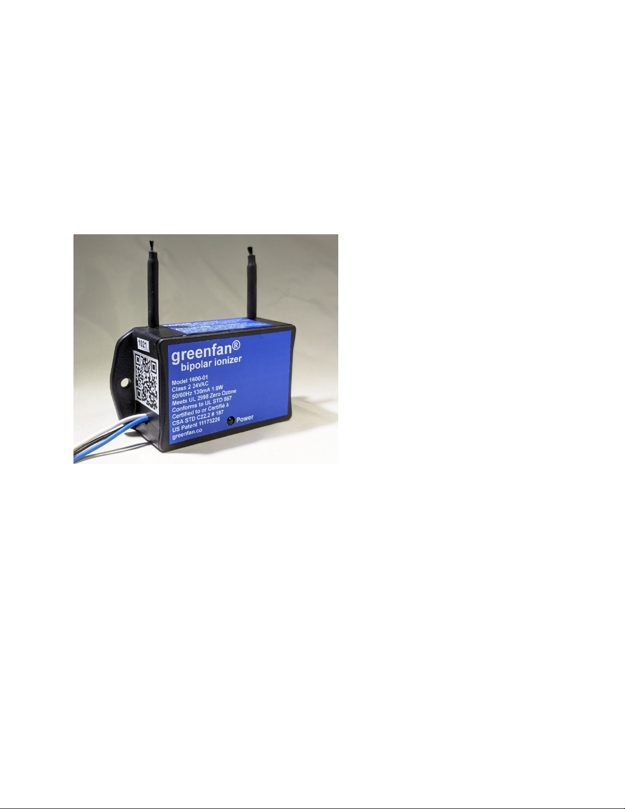
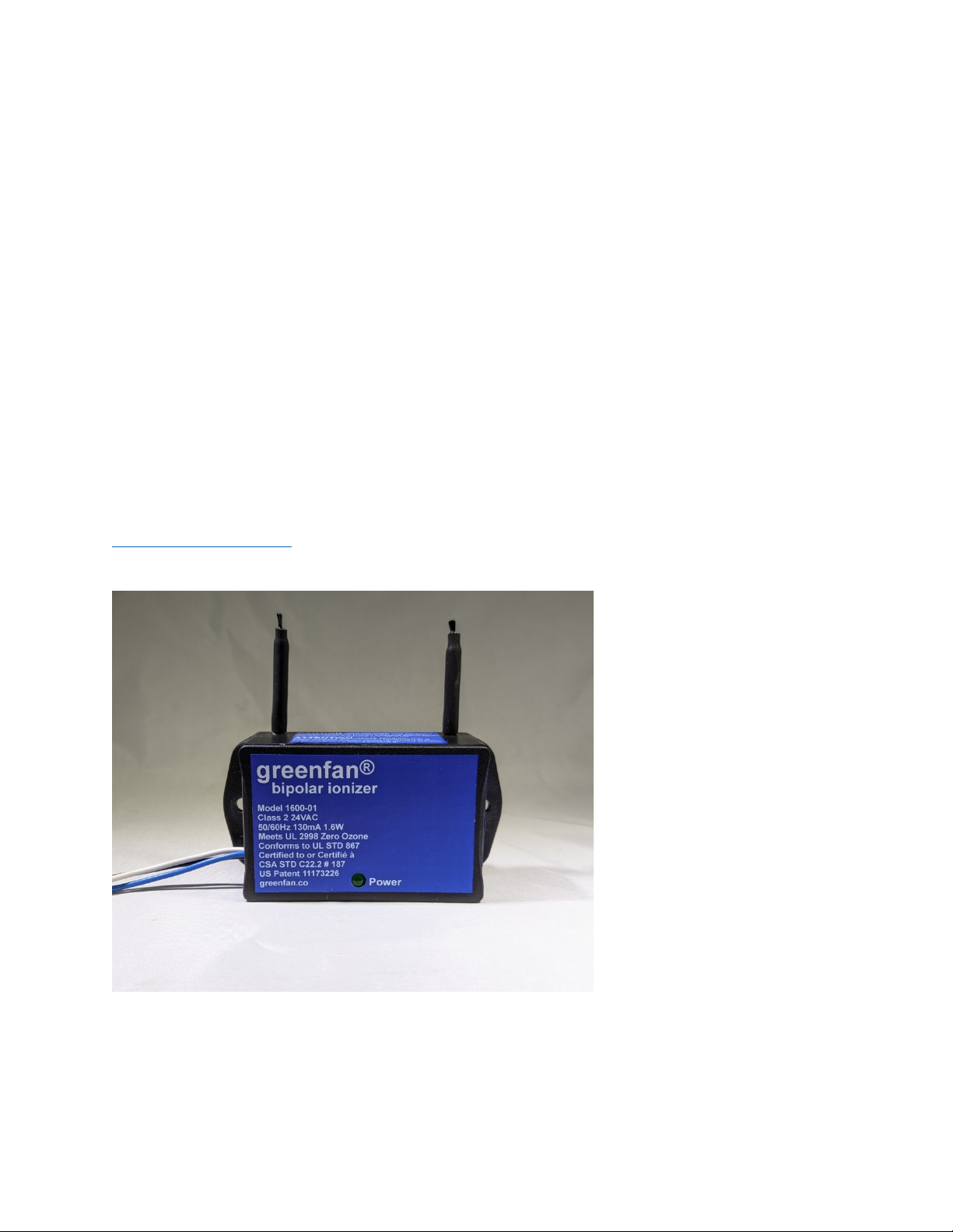
GREENFAN®BIPOLAR IONIZER MODEL 1600-01
© 2021 greenfan® inc. 3
both magnets installed North-South or South-North for ease of installation on the inlet of
an HVAC fan. For an HVAC system, the greenfan® is designed to be activated only
when the HVAC system furnace or fan are activated. For the air purifier or fan, the
greenfan® bipolar ionizer is activated only when the air purifier or fan are turned on.
This saves energy and reduces dust build-up on the electrodes when the fan is off. The
Greenfan® bipolar ionizer must be installed using two sheet metal screws attached
through holes in the flanges on either side of the product.
2.0 TOOLS FOR INSTALLATION AND MAINTENANCE
a) Wire nuts and sheet metal screws (supplied with greenfan® bipolar ionizer).
b) Wireless smart phone compatible snake camera and smart phone compatible
software to view greenfan® bipolar ionizer operation behind the HVAC or FAU
access panel or air purifier cover to verify operation from the thermostat location.
c) Screw or nut drivers to remove or install sheet metal screws.
d) Wire cutter and wire stripper.
e) Multimeter to measure current and or voltage.
f) LED flashlight, vacuum cleaner or compressed air, small brush, or toothbrush.
g) Optional ion counter to measure positive or negative ion concentration
(https://www.alphalabinc.com/product/aic2/)
3.0 DISCONECT POWER BEFORE INSTALLATION
CAUTION: For a packaged unit, disconnect power from the entire HVAC system. For a
split-system disconnect power to the Forced Air Unit (FAU). For an air purifier or
ventilation fan, disconnect power or unplug power cord before installation.
4.0 HVAC FAN INSTALLATION
4.1 HVAC Fan Mechanical Installation
a) WARNING: Disconnect electrical power from the HVAC system before and during
installation. For a packaged unit, disconnect power from the entire HVAC system.
For a split-system disconnect power to the Forced Air Unit (FAU). Do not connect
electrical power until installation is completed.
b) For the HVAC system, the greenfan® bipolar ionizer is installed on the inlet of the
fan of a packaged or split-system with airflow up to 2,000 CFM or cooling capacity
up to 5 tons (60,000 Btu per hour) to deactivate the SARS-CoV-2 virus. Install more
than one greenfan® bipolar ionizer when airflow is greater than 2,000 CFM.
c) For the HVAC system, the greenfan® bipolar ionizer must be installed behind the
access panel on the inlet of the fan and downstream of the air filter and evaporator
coil to help reduce dust build-up on the carbon fiber electrode brushes. Per UL 867,
a caution label is on the product to indicate: “This equipment should be inspected
frequently and collected dirt removed from it regularly to prevent excessive
accumulation that may result in flashover or a risk of fire.”
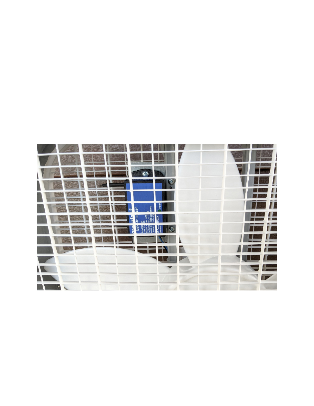
d) For the HVAC system, the greenfan® bipolar ionizer must be installed on the inlet
side of the blower with the carbon fiber electrodes directly in the air stream to allow
airflow to pass through the bipolar ionization plasma as shown in Figure 3.