Greenhouse Style Five-Wall Series User manual

Telephone: 1-800-665-2124 | Fax: 1-888-273-1251
www.greenhousestyle.com • info@greenhousestyle.com
Cross Country
Five-Wall Series
Lean To Greenhouses
Model TLT612FW
GREENHOUSE INSTRUC TIONS
BCG – THE GARDENERS’ CHOICE SINCE 1951
OCTOBER 2008
A5 - 19327- 94th Ave, Surrey, BC, Canada V4N 4E6
Telephone:(604)882-8408•Fax:(604)882-8491•Toll-FreeinNorthAmerica:1- 888-391-4433
Cross Country
Five-Wall Series
Lean To Greenhouses
Model TLT612FW
GREENHOUSE INSTRUC TIONS
BCG – THE GARDENERS’ CHOICE SINCE 1951
OCTOBER 2008
A5 - 19327- 94th Ave, Surrey, BC, Canada V4N 4E6
Telephone:(604)882-8408•Fax:(604)882-8491•Toll-FreeinNorthAmerica:1- 888-391-4433

Contents
Foreword ....................................................................... 2
User Notes ..................................................................... 2
List of Drawings ................................................................. 3
Traditional Straight Series Component List ........................................... 4
Foundations .................................................................... 5
Assembly of the Aluminum Frame
A. Back Gable-End Assembly ....................................................9
B. Front Gable-End Assembly With Door ........................................ 11
C. Sidewall Assembly .........................................................15
Aluminum Frame Installation
1. Side Wall To Back Gable End.................................................16
2. Side Wall To Front Gable End ................................................16
3. Ridge ....................................................................17
4. Truss Assembly Installation (If Necessary) ...........................See Appendix A
5. Poly Bar With Sliders (#1 or #2) ..............................................17
6. Vent Frame Angle ..........................................................17
7. Poly Bars .................................................................25
Taping Poly Bars with Foam .................................................18
8. Fastening The Base/Sill To The Foundation .....................................18
9. Side Vents, Intake Shutter and
Exhaust Fan Installation (if necessary). ...................See Appendices B through E
Poly and Cap Installation
General Information........................................................26
10. Side / Poly Triple Wall......................................................27
11. Roof / Poly Triple Wall......................................................28
12. End Walls / Poly Triple Wall .................................................29
13. Sealing The Greenhouse................................................ 30 & 31
Door And Vent Installation
14. Door Installation ..........................................................32
15. Vent Installation ..........................................................34
16. Vent Assembly ............................................................35
– 1 –
CROSSCOUNTRYFIVE-WALLSERIESSTRAIGHTLEANTO•GREENHOUSEINSTRUCTIONS

Foreword
Your Cross Country greenhouse is designed and constructed to the highest engineering standards
and provides structural strength and maintenance-free service for year-round gardening pleasure.
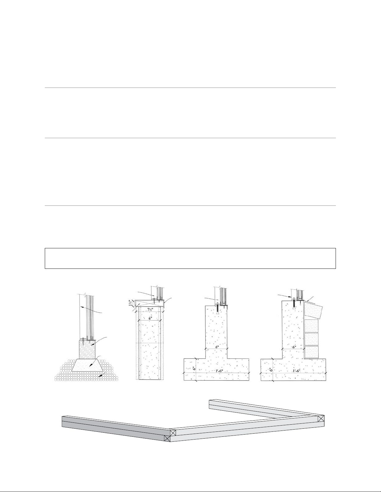
The Cross Country greenhouse must be built upon a firm, level surface. The greenhouse
foundation or sill can be made from pre-treated timbers, concrete or bricks. Whatever your choice
of material, the base must be square and level.
When selecting a site for your greenhouse, keep in mind that a flat, level site is essential so that
the greenhouse can be easily installed and the complete structure is stable and secure. If possible,
choose a site with proper water drainage.
Locating the greenhouse in a north-south position is most suitable for raising summer and autumn
crops since the sun’s rays will be on the greenhouse from daybreak until sunset. An east-west
position is ideal for early spring and winter crops since the winter months, with shorter daylight
hours, still allow six hours of light exposure to the greenhouse.
Try to locate your greenhouse for easy access, especially to the necessary power and water that is
required for greenhouse gardening.
Please watch the enclosed video and follow the steps in this manual for your greenhouse
installation. Remember, if all else fails, read the instructions.
PLEASE NOTE: These instructions are generic. Other standard size greenhouses maintain the same
details as shown. Amendment instruction sketches may be added to some greenhouses at time of
delivery.
User Notes
The Cross Country greenhouse structure has been designed to withstand extreme weather
conditions such as high winds and accumulated snowfall. Hanging baskets and sidewall shelving
can also be attached to its sturdy frame. The greenhouse design also makes it possible to add extra
sections at a later date.
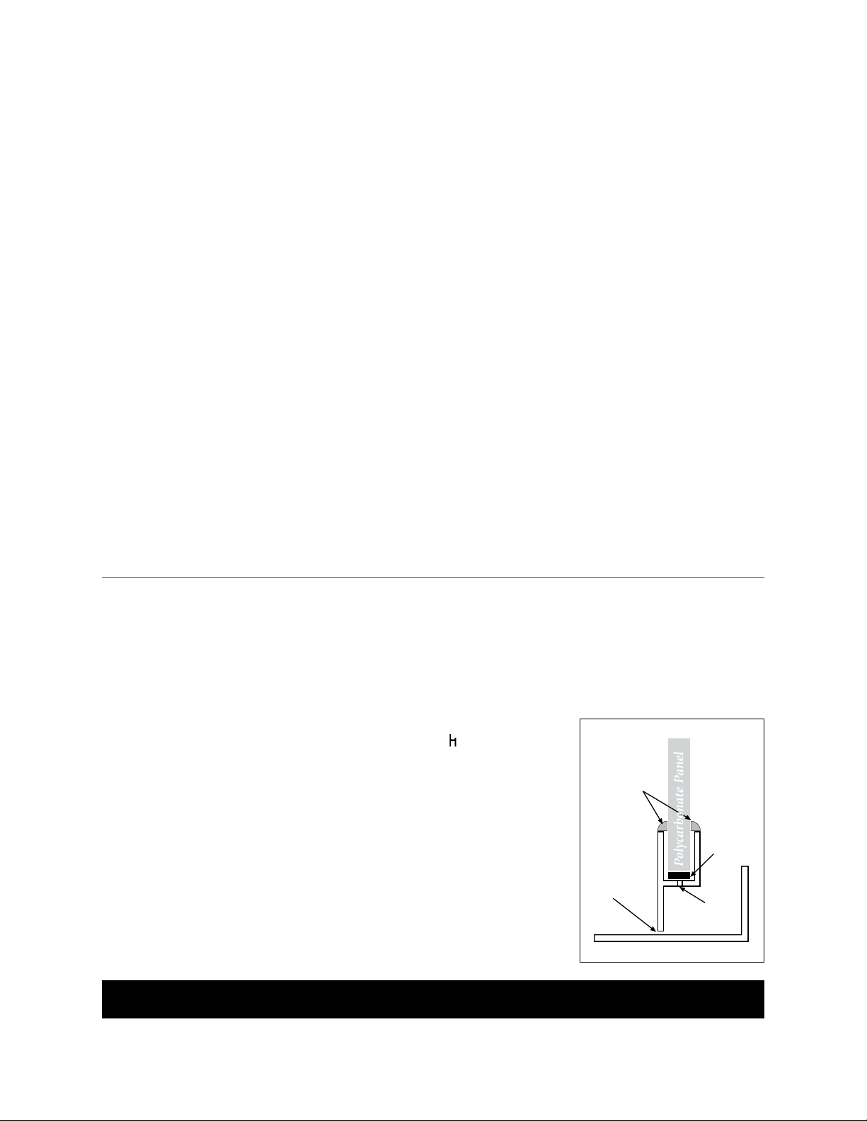
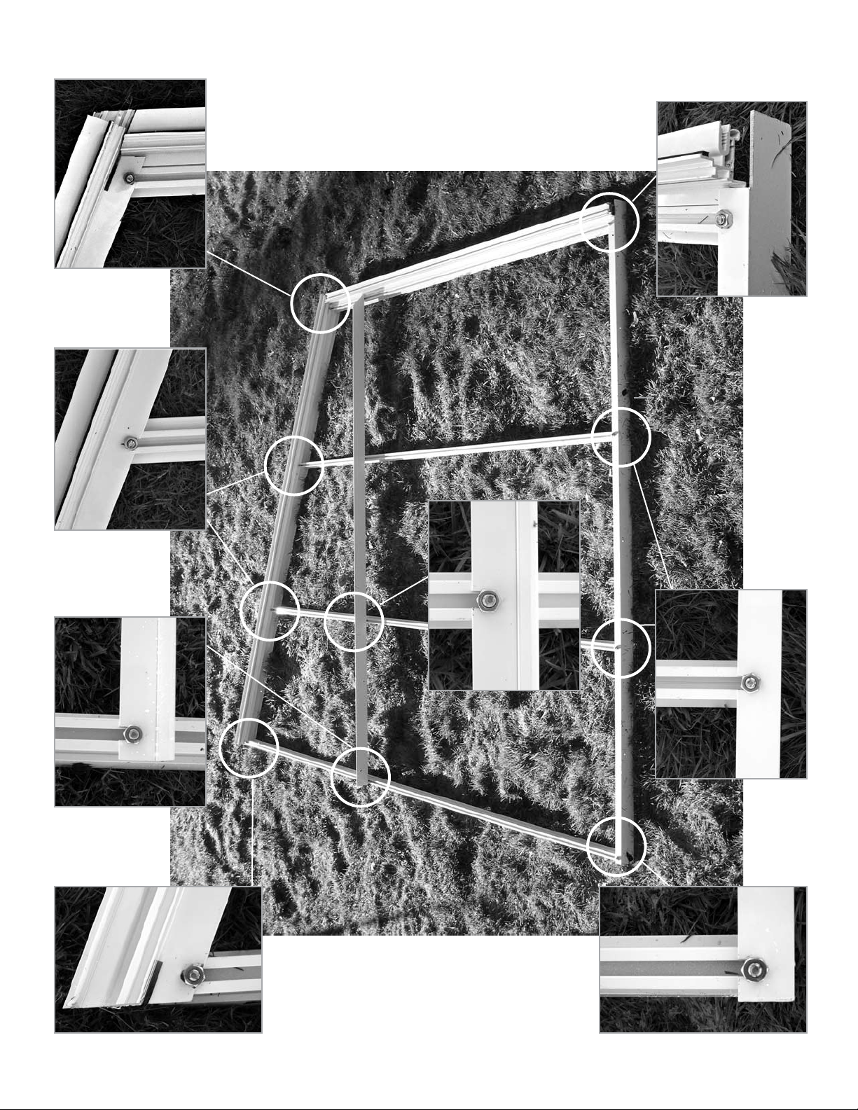
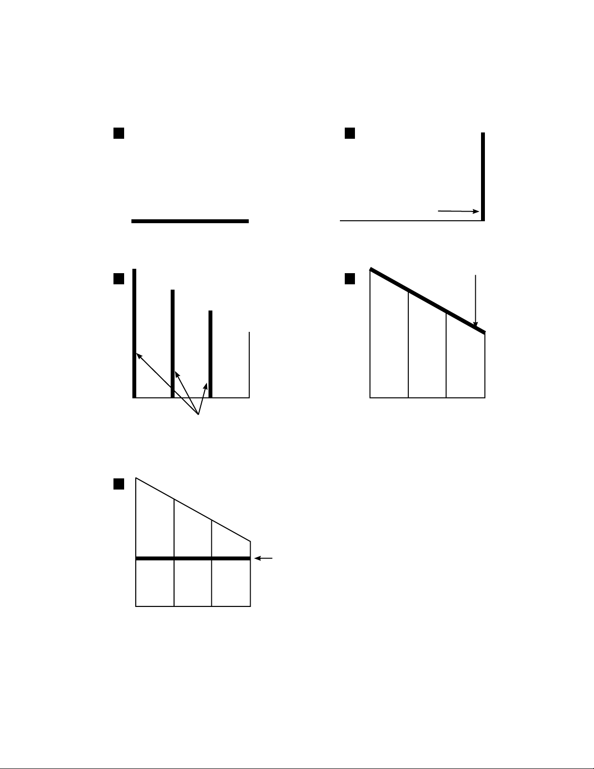
Sealing the polycarbonate sheets to the aluminum “ ” (see sketch)
and base is optional, however we highly recommend it.
By eliminating water from entering the inside of the aluminum, will
prevent excessive moisture inside the panels.
Once a year the greenhouse needs to be completely washed inside
and out. You should do this task when your greenhouse contains the
least number of plants, generally just before the garden plants are
brought in for wintering over. A recommended cleaning solution is a
mixture of soap and water, this will not damage your polycarbonate
sheets. Any benches, shelving, plastic trays, pots and baskets should
also be cleaned thoroughly. Prevention is the best known method for
controlling pests and diseases in the greenhouse.
– 2 –
CROSSCOUNTRYFIVE-WALLSERIESSTRAIGHTLEANTO•GREENHOUSEINSTRUCTIONSNOTE: Do not store polycarbonate sheets in the sun.
Seal
Base
Aluminum H
Drain
Hole
Do NOT
Seal Here!
Setting
Block

List of Drawings
Foundation Styles . . . . . . . . . . . . . . . . . . . . . . . . . . . . . . . . . . . . . . . . . . . . . . . . . . . . . . . . . . . . . . . . 5
Back Gable End Inside View Picture .................................................. 7
Back Gable End Inside View Detail Line Sketch 1 – 5 .................................... 8
Front Gable End Detail Line Sketch 1 – 7 ............................................. 10
Front Gable End Inside View Picture ................................................ 11
Sidewall Inside View ..............................................................15
Assembly Outline Steps 1 – 3 .......................................................19
Steps 4 ..........................................................20
Steps 5 ..........................................................21
Steps 6 ..........................................................22
Steps 7 ..........................................................23
Steps 8 ..........................................................24
Door Installation ..................................................32
Vent Assembly - Exploded View ......................................................33
Vent Detail......................................................................35
Vent Assembly - Exploded View.....................................................36
Motorized Intake Shutter .................................................. Appendix A
Exhaust Fan ............................................................. Appendix B
Side Vent ............................................................... Appendix C
Glass Louvre ............................................................Appendix D
Perlin Installation .........................................................Appendix E
Greenhouse Bench ........................................................Appendix F
Roof Vent Screen .........................................................Appendix G
Side Vent Screen .........................................................Appendix H
Wire Shelving ............................................................Appendix I
Miscellaneous Assembly Details
– 3 –
CROSSCOUNTRYFIVE-WALLSERIESSTRAIGHTLEANTO•GREENHOUSEINSTRUCTIONS

– 4 –
CROSSCOUNTRYFIVE-WALLSERIESSTRAIGHTLEANTO•GREENHOUSEINSTRUCTIONSTool
#2 Square head
screw driver
Measuring tape
Level to check foundation
3/16” concrete bit
(concrete foundation)
9/64” aluminum bit
15/64” aluminum bit
fastening perlins to trusses
(larger greenhouses)
7/16” wrench
Razor blade cutter
Caulking gun
Ladder
Hammer
Optional
Automatic Opener
Circulating Fan
Max/Min Thermometer
Benches
Eyebolts
Motorized Intake Shutter
Exhaust Fan
Thermostat
Heater
Ridge
Cross Country Five-Wall Component List
Poly Cap & Poly Bar End Rafter Ventframe Bottom
Corner Post Aluminum “H” Vent Frame Sides Perlin (if required)
Screws and Bolts Base / Sill Door Frame Gutter

– 5 –
CROSSCOUNTRYFIVE-WALLSERIESSTRAIGHTLEANTO•GREENHOUSEINSTRUCTIONSFoundations
Check your local building codes for foundation requirements in your area.
CONCRETE FOUNDATIONS
When you prepare the concrete foundation, the size should be the same as the greenhouse’s
outside dimensions. One option is to fasten a treated 4” x 4” wooden sill on top of the foundation.
PLEASE NOTE: Especially with concrete, double check all sizes and ensure the forms as square and level
prior to pouring.
PRE-TREATED WOOD FOUNDATIONS
A greenhouse that is 6’, 8’ & 10’ wide can be fastened to a 4” x 4” pre-treated wood timber
foundation. For larger greenhouses, a 6” x 6” wood timber foundation is recommended. These
timbers are placed on a 4” (10 cm) deep and 8” (20 cm) wide gravel bed. Wood timbers can be
stacked to increase the height of the greenhouse. One advantage of the wood foundation is that it is not
classified as a permanent structure. Therefore, if you move, the greenhouse can be dismantled and moved to
another location. IMPORTANT: Please see page 6 regarding treated wood information.
A SQUARE AND LEVEL FOUNDATION
Check the width and length of the foundation’s outside dimensions. Then, square the foundation
by measuring diagonally from opposite corners in the form of an “X”. Next, use a long carpenter’s
level to check and adjust the foundation until it is level. Finally, measure where the door will be
placed (in most cases it is 341/2” wide). Mark these measurements on your foundation.
PRE-TREATED WOOD FOUNDATION
Foundation Styles
Pressure Treated
Wood
4x4, 4x6, 6x6
Concrete Wall or
Concrete Block
with Pressure
Treated Wood
Plate
Concrete Wall
with
Footing
Concrete Wall
with
Footing and
Brick Facing
Gravel
Pre-cast
Concrete Pier
Block
Pressure
Treated
Wood
Pressure
Treated
Wood
Truss on
Models over
13’ Long
Truss on
Models over
13’ Long Truss on
Models over
13’ Long
Truss on
Models over
13’ Long
NOTE:
8” Concrete
Wall on Gable
Ends, models
over 16’ wide
(see detail)
Flashing by
Others
Flashing by
Others
IMPORTANT NOTE: If pressure treated timbers are used, a 10mm polyethylene barrier must be used between the
wood and the aluminum (see page 6)

– 6 –
CROSSCOUNTRYFIVE-WALLSERIESSTRAIGHTLEANTO•GREENHOUSEINSTRUCTIONSPressure Treated Wood
WHAT IS NEW ABOUT PRESSURE TREATED WOOD?
As of January 2005, the chemicals used in pressure treated wood have been changed. Previous
wood was treated with arsenic. However due to the potential long term health hazards this has
been discontinued. New pressure treated wood is treated with copper.
The copper in the ‘new’ wood will be CORROSIVE TO ALUMINUM as well as other metals.
What are ‘Greenhouse Friendly’ solutions to the new pressure treated wood?
1 If you are using the new pressure treated wood, you must place a barrier between the wood
and your aluminum frame. Popular barriers include 10 mil thick plastic sheeting, steel
weather flashing, a rubber or foam weather membrane, or a row of weather resistant non-
treated wood such as cedar or hemlock.
2 Other weather resistant non-treated woods are popular alternatives to pressure treated wood.
These contain no harmful chemicals and will outlast pressure treated wood. Cedar timbers
are a popular choice for greenhouse foundations.
3 Concrete foundations have always been suitable foundation alternatives for greenhouses.
They can vary from poured concrete slabs, poured concrete perimeter walls to concrete block
walls. Although these are usually more costly than wood alternatives, they have the benefit
of lasting a lifetime. As they are usually considered a permanent foundation, it is important
to check with your building codes to determine what you are able to build.
If you have any questions about using the ‘New’ pressure treated wood in conjunction with our
aluminum greenhouses, please contact our office at 1-888-391-4433.

CROSSCOUNTRYFIVE-WALLSERIESSTRAIGHTLEANTO•GREENHOUSEINSTRUCTIONS– 7 –
Back Gable (Inside view)

– 8 –
CROSSCOUNTRYFIVE-WALLSERIESSTRAIGHTLEANTO•GREENHOUSEINSTRUCTIONSBack Gable End Line Drawing Assembly Procedure
1 2
3 4
5
– 8 –
Base
(See #9, Page 4)
(See #5, Page 4)
Corner Post
Poly Bars
(See #2, Page 4)
(See #3, Page 4)
Back Brace
(See #9 or #8 if it is a larger
greenhouse, Page 4)
End Rafter

CROSSCOUNTRYFIVE-WALLSERIESSTRAIGHTLEANTO•GREENHOUSEINSTRUCTIONSA B
Back Gable End Assembly
BUILD BOTH FRONT AND BACK GABLE ENDS ON GROUND FIRST
C
E
D
Base
Corner
Post
All Poly Bars have a track for the
bolts. The track must face up
towards you when you assemble
the gable ends. Slide the bolts
in to the ends or use the notches
that are punched out in the Poly
Bars.
Lay out the back pieces into the
shape of the end wall. See page
6 for details and refer to the line
drawing on page 7.
1. The 1” x 2” angle / base
laying on the ground
should have the 1” side
(with the slot punches out)
facing up. (See Picture A
and Sketch 1, page 8)
2. Bolt the corner post onto
the base angle. (See Picture
Band Sketch 2, page 8) (All
straight cuts of poly bar and
corner post bolt into 1” x 2”
angle)
3. Bolt on all the end bars to
the base. Make sure that the
longest bar is at the end of
the back wall, it will have
holes in it for fastening to
wall (Sketch 3, page 8).
4. End Rafter. When fastening
end rafters to the cornerpost
(See Picture C) and the
long end Poly Bar, leave a
1/8” space for gutters and
ridge (See Picture Dand
Sketch 4, page 8).
5. The angle horizontal brace
is approx. 60” from the
base bolted on with 1/4” x
1/2” bolts. (See Picture E
and Sketch 5, page 8)
Base
End Rafter
Horizontal
Brace
– 9 –

CROSSCOUNTRYFIVE-WALLSERIESSTRAIGHTLEANTO•GREENHOUSEINSTRUCTIONSFront Gable End (with door) Line Drawing Assembly Procedure
1 2
3 4
5
7
6
– 10 –
Base
Corner
Post
End
Rafter
(See #3, Page 4)
Poly Bar
(See #2, Page 4)
Door
Frame
(See #10, Page 4)
(See #5, Page 4)
(See #10, Page 4)
Door
Frame
Header
Plates
(4-hole)
1” x 2”
Door
Frame
Header
(See #9,
Page 4)
1” x 2”
Brace
(See #9,
Page 4)
Poly Bar
above
Door
Poly Bar
(See #2,
Page 4)
Plates
(6-hole)

– 11 –
CROSSCOUNTRYFIVE-WALLSERIESSTRAIGHTLEANTO•GREENHOUSEINSTRUCTIONS

Front Gable End Assembly
Lay out the front pieces into the shape of an end wall. The doorframe and all Poly Bars have a track
for the bolts. The track must face up towards you when you assemble the gable ends. Slide the
bolts in to the ends or use the notches that are punched out in the Poly Bars. Refer to the line/detail
drawings when assembling. (the sketches/drawings/pictures are viewed from inside the greenhouse).
– 12 –
CROSSCOUNTRYFIVE-WALLSERIESSTRAIGHTLEANTO•GREENHOUSEINSTRUCTIONS•Boltthebottomplates(4holes)tothe base/sill and the doorframe sides
using 1/4” x 1/2” stainless steel bolts
(see Picture A, Band Sketch 1, page
10). Before tightening the bolts, be
sure that it is square. (If you ordered
a greenhouse with a door drop, measure
from the bottom of the doorframe to the
underside of the base according to the
specified distance.)For door drop See
Picture Eand Picture F
•Atthetopofthedoorframe,putonthe doorframe header (which looks
the same as the side pieces). Put the
header between the two side pieces
and bolt on the plates (6 holes) (See
Picture Fand Sketch 2, page 10). Use
the 2 oblong holes to fasten doorframe to
header. The plates should stick up 1”
above the doorframe. Note how the
plates are put on. Before tightening
the bolts, be sure to square up the
doorframe.
•Takethecornerpost(anglecutontop) and bolt it to the base (See
Picture Dand Sketch 3, page 10).
Top
Side
Corner
Post
Base
A B
C
D
E F

– 13 –
CROSSCOUNTRYFIVE-WALLSERIESSTRAIGHTLEANTO•GREENHOUSEINSTRUCTIONS•TakethePolyBarsnexttothedoor frame – (see Sketch 4 on Page
9) and bolt them to the base/sill.
The angle cut should match the
roofslope (See Picture E).
The 1” x 2” angle above the door
(493/4” long) can now be bolted
on. The 1/4” round holes should
be lined up with the holes in the
plates (See Picture F). The 2”
side of the angle is facing down. If
you put it the other way the centre
Poly Bar cannot be bolted on. Each
end of the 1” x 2” angle has a slot
punched out to accommodate the
bolt that is lined up with the Poly
Bars 24 1/2” from the center.
Slide a bolt in the top of the Poly
Bar and fasten the angle o it
(See Picture G).
E
F F
G
Front Gable End
Assembly (contd.)

CROSSCOUNTRYFIVE-WALLSERIESSTRAIGHTLEANTO•GREENHOUSEINSTRUCTIONSDoor Frame Assembly

CROSSCOUNTRYFIVE-WALLSERIESSTRAIGHTLEANTO•GREENHOUSEINSTRUCTIONS5. End Rafter - when fastening end rafters to the
corner post, and long Poly Bar, leave a 1/8”
space for the gutter and ridge to slide through
(Picture Hand Sketch 5, page 10). The punch
marks in the end rafter will line up with end
Poly Bars. Slide the bolts in the top of the Poly
Bar before you put on the end rafter.
6. At this point, you can install all the end Poly
Bars. (A smaller greenhouse will only have
1-bar abovethe door) (See Picture Iand Sketch
6, page 10).
7. Smaller sized greenhouses
have a horizonal brace
(See Picture Jand Sketch
7, page 10). Larger sized
greenhouses will have a
diagonal brace from the top
door frame plate to base/sill
2” from the corner post.
H
I
Front Gable End Assembly (contd.)
J
Door
Frame
Horizontal
Brace
Corner
Post
End
Rafter
– 14 –

CROSSCOUNTRYFIVE-WALLSERIESSTRAIGHTLEANTO•GREENHOUSEINSTRUCTIONS1. Take all the Poly Bars and bolt themto
the gutter (See Picture D).start your bars
approximately 25” in from the end of the
gtter and base (See Picture E) (Corner
post will be fastened to the ends when the
greenhouse is assembled.
2. Bolt the Poly Bars to the base. Ensure all
Poly Bars fit tight at gutter and base.
A
B
Sidewall Assembly C
D
E
Lay out the sidewall with the gutter at the top
- base atthe bottom (See Picture A). You will
notice that each sidewall Poly Bar has a straight
and an angle cut. The straight end fits againt
the base (See Picture B) and the angle goes
towardsthe gutter (See Picture C). Always face
the bolt slot in the Poly Bar towards you.
Base
Gutter
Gutter
Base
– 15 –

– 16 –
CROSSCOUNTRYFIVE-WALLSERIESSTRAIGHTLEANTO•GREENHOUSEINSTRUCTIONSA
B
C
1. BACK GABLE END (See Page 19)
Take the assembled back gable end
and stand it up on your foundation.
(Slide a bolt into the top of the
corner post or use the push-out in the
back of the Poly Bar, move it down
approximately 3” and temporarily
tighten the bolt.)
2. SIDE WALL (See Page 19)
Stand up side wall. Slide the gutter
(sidewall) in between the end rafter
and the corner post. (There should
be a 1/8” space - See Picture A). By
sliding the gutter in as far as it goes,
the punched out slots line up with
the bolt track in the backof the Poly
Bar (See Picture B). Undo the bolt
in the corner and slide it up into
the slot and tighten up. Fastenthe
bottom base (See Picture C). Make
sure the side base fits in between the
corner and end base.
3. FRONT GABLE END
(See Page 19)
Follow the same procedure as the
back gable end.
Aluminum Frame Assembly
& Installation
Gutter
End Base
Side Base

– 17 –
CROSSCOUNTRYFIVE-WALLSERIESSTRAIGHTLEANTO•GREENHOUSEINSTRUCTIONSAluminum Frame Assembly
& Installation (contd.) E
G
F
4. RIDGE (See Page 20)
NOTE: Refer to drawings for ridge height.
Before you slide in the ridge, put one bolt
in the top of each end rafter bar (temporarily
tighten). Take the ridge (one person at each
end) and slide it between the end rafter on
the top. You will notice the punched-out
slots in the bottom flange of the ridge. The
end slot lines up with the bottom side of the
end rafter Poly Bar. Now slide in the ridge
and loosen the nut, slide the bolt up into the
ridge slot. Make sure that the Poly Bar is tight
against the ridge – use a 7/16 flat wrench (at
this time you can temporarily fasten the ridge to
keep it rom moving around) (See Picture E).
5. POLY BAR WITH VENT SLIDERS (See
Page 21)
Each Poly Bar may have a small vent frame
slider on it. They are marked 1/2/3/4 etc. On
the ridge there will be the same markings.
Slide a bolt in the top of the Poly Bar. Put
into place with the angle cut on top (Note
that the numbers are the same). Line it up with
the punched out slot in the Ridge. Slide up
the bot and fasten it.
(See Picture F).
6. VENT FRAME BOTTOM SECTION
(See Page 22)
The vent frame bottom fits in between the
Poly Bars that you hve just installed (See
Picture G). The 2” side of the angle faces
towards the Ridge. Move the bolt up the Poly
Bar from he bottom and slide it up to fasten it.
7. REMAINING POLY BARS (See Page 23)
All remaining Poly Bars can now be
installed. Make sure that the top is against
the ridge. Before you tighten the Poly Bar
on the gutter, eyeball the gutter to see if it is
straight. There is usually about a 1/8” space
between the Poly Bar and the gutter.

8. ROOF PURLIN (CHANNEL) (See Page 24)
When installing the roof purlin, mark it out by measuring from the ridge. The roof purlin
should be located approximately the center between the ridge and the gutter, on models
up to 16’ wide. Models over 16’ have extra purlins. Always face the open end of the purlin
up towards the ridge so that it can be used for hanging baskets. Every Poly Bar has notches
punched out so that the head of the bolts can be inserted and can slide up or down on the
bar (for larger greenhouses the purlin will be thicker and heavier and you will have to use longer
bolts, 1/4” x 3/4”, to fasten the Poly Bar to fit).
9. TAPE ALL POLY BARS (See Page 25)
Complete all taping with the 1/8” foam tape - install side vent frame sliders before taping the bars
(if it was not done before).
Don’t put foam strips between the poly and the base, and beside the door frame and gutter.
1O. FASTENING THE BASE
(See Pages 30 & 31)
Use caulking to seal the base to the
foundation as well as against the wall,
behind the ridge / upright bars. Before
you seal behind the ridge and end Poly
Bars, square your greenhouse using the 3/4/5 method
(see sketch). Sometimes the foundation is level but your wall is not plumb. You may have
to decide to pull the greenhouse away from the wall or make your foundation off-level.
When your greenhouse is squared up, mark the edge of the ridge on your wall and pull your
greenhouse away from the wall and seal behind it. Push the greenhouse back to the wall and
fasten it with screws. NOTE: Sealing can also be done after greenhouse is finished and before the
vents are installed.
11. SIDE VENTS, INTAKE SHUTTER AND EXHAUST FANS INSTALLATION
(IF NECESSARY) SEE APPENDIXES B THRU E. THEN RETURN TO THE
NEXT PAGE AND CONTINUE
Note: Make sure the greenhouse is fastened to the foundation with 1” screws. Square
corner-to-corner and ensure base/sill is level.
IMPORTANT OPTIONALS
SIDE VENTS, INTAKE SHUTTERS AND EXHAUST FAN INSTALLATION: See Appendix B-E
(Pages 39 – 41).
TRUSS: If the greenhouse is larger than the instructions show, it will require a truss.
Insert a truss after the Ridge (See #4 Page 17). Follow up with installation of the Perlin
(See #8, this page). Truss assembly sketch is on Page 36.
– 18 –
CROSSCOUNTRYFIVE-WALLSERIESSTRAIGHTLEANTO•GREENHOUSEINSTRUCTIONS1
This manual suits for next models
1
Table of contents
Other Greenhouse Style Greenhouse Kit manuals