Greenhouse Style Pride of the Pacific Series User manual

Pride of the Pacific Series
Curved Glass Lean To
Model PLT612SG
GREENHOUSE INSTRUCTIONS
BCG – THE GARDENERS’ CHOICE SINCE 1951
OCTOBER 2008
A5 - 19327- 94th Ave, Surrey, BC, Canada V4N 4E6
Telephone: (604) 882-8408 • Fax: (604) 882-8491 • Toll-Free in North America: 1-888-391-4433
Pride of the Pacific Series
Curved Glass Lean To
Model PLT612SG
GREENHOUSE INSTRUCTIONS
BCG – THE GARDENERS’ CHOICE SINCE 1951
OCTOBER 2008
A5 - 19327- 94th Ave, Surrey, BC, Canada V4N 4E6
Telephone: (604) 882-8408 • Fax: (604) 882-8491 • Toll-Free in North America: 1-888-391-4433
Telephone: 1-800-665-2124 | Fax: 1-888-273-1251

Contents
Foreword ....................................................................... 2
User Notes ..................................................................... 2
List of Drawings ................................................................. 3
Pride of the Pacific Component List ................................................. 4
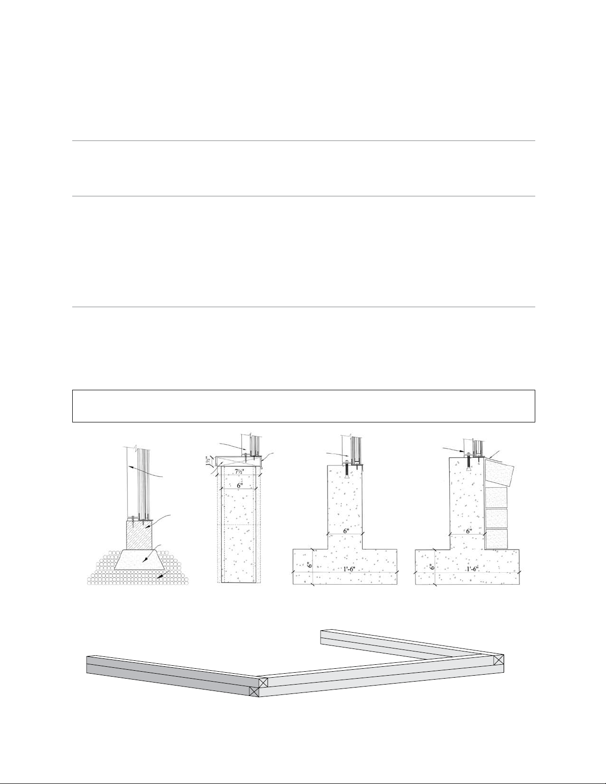
Foundations .................................................................... 5
Assembly Of The Aluminum Frame
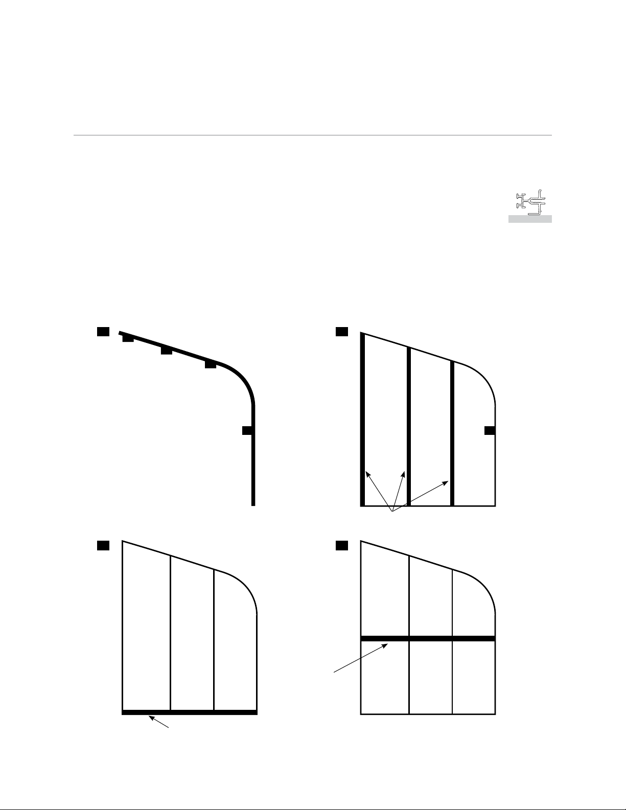
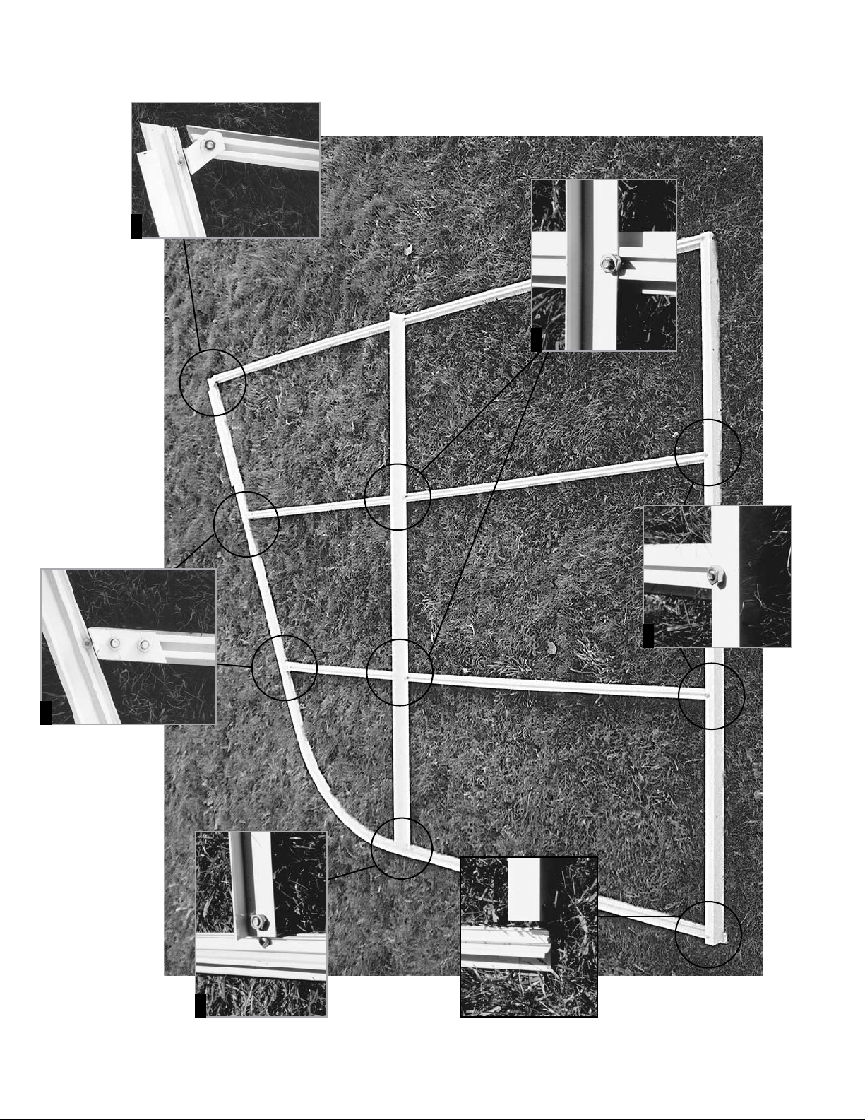
A. Back Gable End Assembly ................................................... 7
B. Front Gable End Assembly With Door ..........................................9
C. Taping Glass Bars With Foam ............................................... 12
Aluminum Frame Installation
1. Side Base/Sill............................................................. 13
2. Front Gable End .......................................................... 13
3. Back Gable End........................................................... 13
4. Ridge ................................................................... 13
4A. Truss Assembly Installation (if necessary) ...........................See Appendix A
5. Glass bars With Sliders (#1 or #2)............................................ 13
6. Ventframe Angle .......................................................... 14
7. Glass bars ............................................................... 14
8. Gutter................................................................... 14
9. Roof Purlin (Channel) ..................................................... 14
10. Center Bars .............................................................. 14
11. Tape All Glass bars ........................................................ 14
11A. Side Vents, Intake Shutter and Exhaust Fan Installation (if necessary)...See Appendix B - E
Glass And Cap Installation
General Information....................................................... 22
12. Glazing ................................................................. 22
13A-E. Side Walls ............................................................22 - 26
14. Ends .................................................................... 26
15. Sealing The Greenhouse.................................................... 26
Door And Vent Installation
16. Door Installation ......................................................... 27
17. Vent Assembly ........................................................... 29
18. Vent Installation .......................................................... 29
Appendices: Optional Installations
Truss Installation .................................................. Appendix A
Vent Opener ...................................................... Appendix B
Exhaust Fan ....................................................... Appendix C
Side Vent . . . . . . . . . . . . . . . . . . . . . . . . . . . . . . . . . . . . . . . . . . . . . . . . . . . . . . . . . Appendix D
Glass Louvre ...................................................... Appendix E
Perlin Installation ...................................................Appendix F
Greenhouse Bench .................................................Appendix G
Roof Vent Screen...................................................Appendix H
Side Vent Screen ....................................................Appendix I
Wire Shelving ......................................................Appendix J
Miscellaneous Assembly Details: 1–3
– 1 –

Foreword
Your Pride of the Pacific greenhouse is designed and constructed to the highest engineering standards
and provides structural strength and maintenance-free service for year-round gardening pleasure.
The Pride of the Pacific greenhouse must be built upon a firm, level surface. The greenhouse
foundation or sill can be made from pre-treated timbers, concrete or bricks. Whatever your choice
of material, the base must be square and level.
When selecting a site for your greenhouse, keep in mind that a flat, level site is essential so that
the greenhouse can be easily installed and the complete structure is stable and secure. If possible,
choose a site with proper water drainage.
Locating the greenhouse in a north-south position is most suitable for raising summer and autumn
crops since the sun’s rays will be on the greenhouse from daybreak until sunset. An east-west
position is ideal for early spring and winter crops since the winter months, with shorter daylight
hours, still allow six hours of light exposure to the greenhouse.
Try to locate your greenhouse for easy access, especially to the necessary power and water that is
required for greenhouse gardening.
Please watch the enclosed video and follow the steps in this manual for your greenhouse
installation. Remember, if all else fails, read the instructions.
User Notes
The Pride of the Pacific greenhouse structure has been designed
to withstand extreme weather conditions such as high winds and
accumulated snowfall. Hanging baskets and sidewall shelving can
also be attached to its sturdy frame. The greenhouse design also
makes it possible to add extra sections at a later date.
Once a year the greenhouse needs to be completely washed inside
and out. You should do this task when your greenhouse contains
the least number of plants, generally just before the garden plants
are brought in for wintering over. A recommended cleaning
solution is a mixture of hot water with a disinfectant such as Lysol
or Pinesol. Any benches, shelving, plastic trays, pots and baskets
should also be cleaned thoroughly. Prevention is the best known
method for controlling pests and diseases in the greenhouse.
– 2 –
PLEASE NOTE: The
Illustrations found
in this manual may
not be specific to your
greenhouse, however
the detail of aluminum
shapes are all consistent.
The user notes are a
generic instruction for
all Pride of the Pacific
Series Greenhouses
– assembly instructions
are common, only the
sizes number of pieces
and sizes vary.

List of Drawings
Pride Of The Pacific Component List ................................................ 4
Foundation Styles . . . . . . . . . . . . . . . . . . . . . . . . . . . . . . . . . . . . . . . . . . . . . . . . . . . . . . . . . . . . . . . . 5
Back Gable End Line Drawing Assembly Procedure .....................................7
Back Gable End Detail Drawing – Details 1 – 4 .........................................8
Front Gable End (With Door) Line Drawing Assembly Procedure ........................ 10
Front Gable End (With Door) Detail Drawing – Details 5 – 10........................... 11
Assembly Outline: Aluminum Frame Steps 1 – 10..................................15 - 21
Glass Installation Steps 12 – 14 ................................. 22 - 26
Door Installation................................................................ 28
Vent Assembly - Exploded View.................................................... 30
Greenhouse Architectural Details ................................................31-32
Truss Installation......................................................... Appendix A
Vent Opener ............................................................ Appendix B
Exhaust Fan ............................................................. Appendix C
Side Vent ...............................................................Appendix D
Glass Louvre ............................................................ Appendix E
Perlin Installation .........................................................Appendix F
Greenhouse Bench .......................................................Appendix G
Roof Vent Screen .........................................................Appendix H
Side Vent Screen ..........................................................Appendix I
Wire Shelving ............................................................Appendix J
– 3 –

Pride of the Pacific Component List
Tools
#2 Square head
screw driver
Measuring tape
Level to check foundation
3/16” concrete bit
(concrete foundation)
9/64” aluminum bit
7/16” wrench
Razor blade cutter
Caulking gun
Ladder
Hammer
Optionals
Automatic Opener
Circulating Fan
Max/Min thermometer
Benches
Eyebolts
Motorized Intake Shutter
Exhaust Fan
Thermostat
Heater
– 4 –
1/2 Ridge Glass Cap & Glass Bar Glass End Bar Ventframe Bottom
Bracing Angle Plastic h came Vent Frame Sides Purlin (if required)
Screws and Bolts Base / Sill Door Frame Gutter

– 5 –
Foundations
Check your local building codes for foundation requirements in your area.
CONCRETE FOUNDATIONS
When you prepare the concrete foundation, the size should be built to the exact greenhouse’s
outside dimensions.
PRE-TREATED WOOD FOUNDATIONS
A greenhouse that is approximately 100 sq. ft. (9.3 m2) can be fastened to a 4” x 4” pre-
treated wood timber foundation. For larger greenhouses, a 6” x 6” wood timber foundation is
recommended. These timbers are placed on a 4” (10 cm) deep and 8” (20 cm) wide gravel bed.
Wood timbers can be stacked to increase the height of the greenhouse. One advantage of the wood
foundation is that it is not classified as a permanent structure. Therefore, if you move, the greenhouse can be
dismantled and moved to another location.
A SQUARE AND LEVEL FOUNDATION
Check the width and length of the foundation’s outside dimensions. Then, square the foundation
by measuring diagonally from opposite corners in the form of an “X”. Next, use a long carpenter’s
level to check and adjust the foundation until it is level. Finally, measure where the door will be
placed (in most cases it is 341/2” wide). Mark these measurements on your foundation.
PRE-TREATED WOOD FOUNDATION
Foundation Styles
Pressure Treated
Wood
4x4, 4x6, 6x6
Concrete Wall or
Concrete Block
with Pressure
Treated Wood
Plate
Concrete Wall
with
Footing
Concrete Wall
with
Footing and
Brick Facing
Gravel
Pre-cast
Concrete Pier
Block
Pressure
Treated
Wood
Pressure
Treated
Wood
Truss on
Models over
13’ Long
Truss on
Models over
13’ Long
IMPORTANT NOTE: If pressure treated timbers are used, a 10mm polyethylene barrier must be used between the
wood and the aluminum (see page 6)
Truss on
Models over
13’ Long
Truss on
Models over
13’ Long
NOTE:
8” Concrete
Wall on Gable
Ends, models
over 16’ wide
(see detail)
Flashing by
Others
Flashing by
Others

– 6 –
Pressure Treated Wood
WHAT IS NEW ABOUT PRESSURE TREATED WOOD?
As of January 2005, the chemicals used in pressure treated wood have been changed. Previous
wood was treated with arsenic. However due to the potential long term health hazards this has
been discontinued. New pressure treated wood is treated with copper.
The copper in the ‘new’ wood will be CORROSIVE TO ALUMINUM as well as other metals.
What are ‘Greenhouse Friendly’ solutions to the new pressure treated wood?
1 If you are using the new pressure treated wood, you must place a barrier between the wood
and your aluminum frame. Popular barriers include 10 mil thick plastic sheeting, steel
weather flashing, a rubber or foam weather membrane, or a row of weather resistant non-
treated wood such as cedar or hemlock.
2 Other weather resistant non-treated woods are popular alternatives to pressure treated wood.
These contain no harmful chemicals and will outlast pressure treated wood. Cedar timbers
are a popular choice for greenhouse foundations.
3 Concrete foundations have always been suitable foundation alternatives for greenhouses.
They can vary from poured concrete slabs, poured concrete perimeter walls to concrete block
walls. Although these are usually more costly than wood alternatives, they have the benefit
of lasting a lifetime. As they are usually considered a permanent foundation, it is important
to check with your building codes to determine what you are able to build.
If you have any questions about using the ‘New’ pressure treated wood in conjunction with our
aluminum greenhouses, please contact our office at 1-888-391-4433.

Assembly of Aluminum Frame
A. BACK GABLE END ASSEMBLY
Lay out the back pieces into the shape of the end wall. Refer to the line/detail drawing.
1. For the curved glass end bars, the flat surface should lie on the ground
(See the example to the right. Use the curved end bar with an angle cleat attached to the side).
2. Bolt the Glass Bars on the top first (See Detail #1 & 1A, Page 8).
3. Bolt the base/sill to the bottom of the Glass Bars (See Detail #2, Page 8).
4. The angle brace is bolted approximately 56” from the base. The slider brackets that have
already been fastened to the poly end bar curve will determine the height (See Detail #3, Page
8). When bolting the horizontal cross brace onto the back wall, measure the back wall so that
it does not sag (See Detail #4, Page 8).
– 7 –
Back Gable End Line Drawing Assembly Procedure
Curved Glass End Bars Glass Bars
1” x 2” Angle Base
Cross
Brace
GROUND
1 2
3 4

Back Gable End
Detail Drawing –
Details 1 – 4
3
1
1A
4
2
– 8 –

B. FRONT GABLE END ASSEMBLY WITH DOOR
1. Lay out the front pieces of the greenhouse into the shape of an end wall. The door frame and
all the Glass Bars have a track for the bolt. The track must face up when you assemble the
gable ends. Slide the bolts into the track of the bars or use the notches that have already been
punched out in the bars. (Refer to the line/detail drawing on the following page. The order
of assembly is represented by dark lines. Detailed pictures are on page 11.) When you are
assembling the greenhouse, you can view the sketches and drawings from the inside the
greenhouse. Bolt the bottom plates
(4 holes) to the base/sill and the door frame sides using
1/4” x 1/2” stainless steel bolts (see Detail #5, page 11). Before tightening the bolts, be sure
that it is square (If you ordered a greenhouse with a door drop, measure from the bottom of
the door frame to the underside of the base according to the specified distance).
2. At the top of the door frame, put on the door frame header (which looks the same as the side
pieces). Put the header between the two side pieces and bolt on the plates (6 holes). (See
Detail #6). The plates should stick up 1” above the door frame. Note how the plates are put
on (See Detail #7). Before tightening the bolts, be sure to square up the sill to the door frame.
3. Take all the Glass Bars and bolt them to the base/sill. The angle cut should match the roof
slope (See Detail #8).
4. The 1” x 2” angle above the door (49 3/4” long) can now be bolted on. The 1/4” round
holes should be lined up with the holes in the plates. Each end of the 1” x 2” angle has a slot
punched out to accommodate the bolt. This slot lines up with the bolt track in the back side
of the Glass Bars. Slide a bolt in the top of the Glass Bar and fasten the angle to it (See Detail
#6 & 9).
5. Curved Glass End Bar. Each glass end bar has at least one small aluminum bracket attached
to it with two 1/4” holes drilled in it. These pieces line up with the upright Glass Bar(s).
6. When the upright Glass Bars are fastened to the aluminum bracket that is attached to the
curved glass end bar, bolt on the short Glass Bar above the door to the 1” x 2” angle.
7. The diagonal bracing can now be bolted on. Remove the bottom nut in the top plate and
insert the brace. Then put the nut back on (See Detail #4 & #9). Bolt the other end to the 1/4”
hole in the base using a 1/4” x 1/2” bolt (See Detail #10).
NOTE: You may want to fasten a temporary brace across the bottom of the door frame to keep them
together. This can be a piece of wood, make sure that the opening is the same as on the top of the door
frame.
– 9 –

– 10 –
Front Gable End (with door) Line Drawing Assembly Procedure
1 2
3 4
5 6
7
Curved
Glass
End Bar
Diagonal
Angle Brace
Door
Frame
Sides
Plate
1” x 2” Angle
Glass Bar
Glass Bar
Plates
Door Frame Top

Front Gable End (with door)
Detail Drawings
Details 5 – 10
Curved
Glass End
Bar
Curved
Glass End
Bar
9
10
5
6
78
Diagnol
Brace
Diagnol
Brace Door
Frame
Door
Frame
– 11 –

Door Frame Assembly

C. TAPING GLASS BARS WITH FOAM
Tape all the aluminum Glass Bars with 1/8” foam tape. The curved glass end bars tape on one
side only. All other Glass Bars tape on both sides. Take a roll of tape and start at one end and
press on the bar. Make sure that the aluminum is dry. Taping it at this time, you can still move
all the pieces in the shed or undercover if it is raining.) Slowly roll down the tape toward
the outer edge and press it down at the same time. (See pictures below) Be careful because
sometimes the edge of the paper is quite sharp. Do not remove the paper until later.
NOTE: Do not tape the place where the Glass Bar is notched out.
When all bars are completed, including the end walls, go to Step #1 of the aluminum frame
installation on the next page.
– 12 –
Do NOT put foam tape along the End Bars.
The glass slides under the lip and needs to be sealed
when the greenhouse is finished

Aluminum Frame Installation
Check that the foundation is level and square. If your
foundation is larger than the greenhouse, mark a line on it
with a pencil or with a chalk line. Take a caulking gun and
put in a tube of caulking. Cut 1/4” off the top at a 25-degree
angle. Then put a bead of caulking on your foundation
approximately 1” in from the outside of the foundation or
the marked line. DO NOT CAULK THE DOOR OPENING.
Measure your door opening in the front.
1. SIDE BASE/SILL
Lay down the aluminum side base/sill flush with your base on the line you have marked out.
Push down on it so that the caulking squeezes out. (See Step 1 Detail, page 14.)
2. FRONT GABLE END
Stand up the door end, flush with your base or marked line. Slide up one bolt in the bottom
of curved glass end bar (front). Take the end bar and push it into the side base where it is
notched. The back of the bar lines up with the first slot in the side base/sill. Slide the bolt
down and fasten it. When you are lined up and in the right place, screw down the front base/
sill using the screw holes that are already there. Then put one screw in the side base to hold it
in place. When you have fastened down the front, it should stand by itself. (If it is windy, you
will need another person to hold up the front, or you can use a stepladder so that the front
can lean against it.) Next plumb the glass bar against the wall and put in 1” screw for now.
(NOTE: after the greenhouse frame is up, double check for square and plumb. Seal behind the glass
bar and the ridge, then put in all the screws.) (See Step 2 Detail, page 15.)
3. BACK GABLE END
Follow the same procedure for the back gable end as you did for the front. When you have
bolted it to the side base and it lines up flush with your base/sill or marked line, then you can
proceed. Fasten the base/sill down to your foundation with the 1” screws that are provided.
When fastening the side/base sill to the foundation, be sure that the base is straight.
(See Step 3 Detail, page 15.)
4. RIDGE
Before you slide in the ridge, put one bolt in the top of each end bar. Take the ridge (one
person at each end) and slide it between the end bars on the top. You will notice the punched-
out slots in the bottom flange of the ridge. The slots on the end line up with the bottom side
of the end bar. Now slide in the ridge and slide the bolt into the ridge slot. Make sure that the
glass end bar is tight against the ridge – use a 7/16 flat wrench (at this time you can temporarily
fasten the ridge to keep it from moving around - measure ridge height, don’t rely on gable bars).
4A. SEE APPENDIX A FOR TRUSS ASSEMBLY INSTALLATION FOR
GREENHOUSES LONGER THAN 16 FEET.
5. CURVED GLASS BAR WITH SLIDERS (1, 2, 3 etc.)
Each Glass Bar (with a vent frame slider) is marked with a number (1, 2, 3 . . .) to correspond
with the number on the ridge. Slide the bolt into the top of the Glass Bar and line it up with
the slot in the ridge. Move up the bolt and fasten it. Do the same for the bottom of the Glass
Bar. Slide in the bolt, lift up the end, and push it into the side base/sill as far as you can. Then
bolt it on. Do this for all the Glass Bars with sliders and numbers. The end of the bar should
be tight to the base. (See Step 5 Detail, page 17.)
– 13 –

6. VENTFRAME ANGLE
The ventframe angle is 50” long with the ends cut out to fit between the two Glass Bars with
sliders. Put the head of the bolt into the punch out in the glass bar (24” from the top), slide
the bolt up and fasten it to the ventframe on the bar. Make sure that the angle flanges are
facing toward the sidewall (down) and that it is pushed up against the side sliders (already
on the Glass Bar). Do this for all of them.
(See Step 6 Detail, page 18.)
7. GLASS BARS
Bolt on all the remaining Glass Bars. Make sure that the top and bottom is tight against the
ridge and base. (See Step 7 Detail, page 19.)
8. GUTTER
The gutter is also used as a spacebar. The gutter is located just below the curve approximately
54” up from the base (The glass bar should be notched out for it). Use #8 x 1/2” screws to fasten
the gutter to the glass bar (Keep the gutter to the top of the notch).
(See Step 8 Detail, page 20.)
9. ROOF PURLIN (CHANNEL)
When installing the roof purlin, mark it out by measuring from the ridge. The roof purlin
should be located approximately 6” above the place where the curve starts (See drawings
provided for purlin locations). In larger greenhouses, the purlin may be located about the center
between the ridge and the top of the curve. Always face the open end of the purlin up towards
the ridge so that it can be used for hanging baskets. Every Glass Bar has notches punched out
so that the head of the bolts can be inserted and can slide up or down on the bar. (See Step 9
Detail, page 21.)
10. TAPE ALL GLASS BARS
Complete all taping with the 1/8” foam gasket. NOTE: Side vents need to be installed before
taping the bars (See photographs, page 12.)
11. FASTENING / SEALING THE GREENHOUSE TO THE WALL
Before you seal behind the ridge and end glass bars, square your greenhouse using the
3/4/5 method (see sketch). Sometimes the foundation is level but your wall is not plumb.
You may have to decide to pull the greenhouse
away from the wall or make your foundation off-
level. When your greenhouse is squared up, mark
the edge of the ridge on your wall and pull your
greenhouse away from the wall and seal behind it.
Push the greenhouse back to the wall and fasten
it with screws. NOTE: Sealing can also be done after
greenhouse is finished and before the vents are installed.
11A.SIDE VENTS, INTAKE SHUTTER AND EXHAUST FANS INSTALLATION
(IF NECESSARY) SEE APPENDIXES B THRU E. THEN RETURN TO THE
NEXT PAGE AND CONTINUE
– 14 –
3
4
53/64/8
5/10

Step 1: Side Sill & Base
Assembly Outline
Step 2:
Front
Gable
End . . . .
Step 3:
Back
Gable
End
Front Gable End
– 15 –

Step 4: Ridge
– 16 –
4
4
1
1

Step 5: Glass Bar with
Vent Frame Sliders
– 17 –
3
2
2
3

– 18 –
Step 6: Vent Frame Bottom
Inside
View
This manual suits for next models
1
Table of contents
Other Greenhouse Style Greenhouse Kit manuals