GREWIN PCLC-901D User manual

TIANJIN GREWIN TECHNOLOGY CO.,LTD.
Web:www.grewin-tech.com WhatsApp:+86-13072088960
Email:[email protected]
Address:DongLi Distr Tianjin City, China Tel: +86-22-84943756
0
We reserve all right in this document and in the information contained within. Reproduction, use or disclosure to third partners without express
authorization is strictly forbidden. V5.0
PCLC-901D CABLE FAULT LOCATOR
*FAULT PRE-LOCATING DEVICE
V 5.0

TIANJIN GREWIN TECHNOLOGY CO.,LTD.
Web:www.grewin-tech.com WhatsApp:+86-13072088960
Email:[email protected]
Address:DongLi Distr Tianjin City, China Tel: +86-22-84943756
1
NOTICE
Thank you for choosing our devices.
Read the instruction carefully before using,specially pay attention to the security warning and tips.
Please don’t maintain device by yourselves. Contact us if any breakdown or error.
CATALOG
1. General description••••••••••••••••••••••••••••••••••••••••••••••••••3
1.1 General•••••••••••••••••••••••••••••••••••••••••••••••••••••••3
1.2 Function feather••••••••••••••••••••••••••••••••••••••••••••••••3
1.3 Specification•••••••••••••••••••••••••••••••••••••••••••••••••••5
2. Physical characteristics and operation••••••••••••••••••••••••••••••••••••6
2.1 Configuration•••••••••••••••••••••••••••••••••••••••••••••6
2.2 Main unit panel••••••••••••••••••••••••••••••••••••••••••••6
2.3 Menu introduction•••••••••••••••••••••••••••••••••••••••••••7
2.4 Basic operation••••••••••••••••••••••••••••••••••••••••••••••10
3. Low voltage impulse mode•••••••••••••••••••••••••••••••••••••••••••20
3.1 General •••••••••••••••••••••••••••••••••••••••••••••••••••••20
3.2 Working principle••••••••••••••••••••••••••••••••••••••••••••••20
3.3 Testing steps••••••••••••••••••••••••••••••••••••••••••••••••••21
4. Impulse current mode ••••••••••••••••••••••••••••••••••••••••••••••26
4.1 General •••••••••••••••••••••••••••••••••••••••••••••••••••••26
4.2 Principle ••••••••••••••••••••••••••••••••••••••••••••••••••••26
4.3 Testing steps••••••••••••••••••••••••••••••••••••••••••••••••••28
5. Multiple impulse mode•••••••••••••••••••••••••••••••••••••••••••••33
5.1 Main introduction•••••••••••••••••••••••••••••••••••••••••••••33
5.2 Principle ••••••••••••••••••••••••••••••••••••••••••••••••••••33
5.3 Testing steps••••••••••••••••••••••••••••••••••••••••••••••••••35
6. Computer online••••••••••••••••••••••••••••••••••••••••••••••••••39
7. Charge and maintain•••••••••••••••••••••••••••••••••••••••••••••••40

TIANJIN GREWIN TECHNOLOGY CO.,LTD.
Web:www.grewin-tech.com WhatsApp:+86-13072088960
Email:[email protected]
Address:DongLi Distr Tianjin City, China Tel: +86-22-84943756
2
1. GENERAL DESCRIPTION
1.1 GENERAL :
The PCLC-901D Power Cable Fault Pre-locator is an easy operation device used for distance locating . It’s easy to operate,support both touch
screen/button operation and with friendly interface.
PCLC-901D can be used alone under the low voltage impulse mode.
Under the mode of impulse current,PCLC-901D needs to work with HVSG-500GX high voltage generator items.Under the multiple impulse
mode,PCLC-901D also need PCLC-900C coupler.After distance locating,user could use PCLD-901P items for fault pinpointing. And these products can
be combined into a set of high performance and innovative cable fault testing system.
1.2 FUNCTION FEATHER:
Multiple distance locating method:
-Low current impulse method: apply to the locating of the low resistance fault. Short circuit fault, open circuit fault. It also can be used in the
measurement of the cable length, the intermediate joints, T joints, and cable termination joint. This method also can be used to correct the
wave velocity.
-Impulse current method: apply to the high resistance fault, breakdown fault. Use the current coupler to gather signal from the earth wire
-Multiple impulse method: improvement of the SIM method
200MHz real-time sampling
-Advance tech.Upgrading for SIM method
-Max. 0.4m measurement resolution,PCLC-901D has small blind zone and is special for the short cable and nearly-terminal fault cable
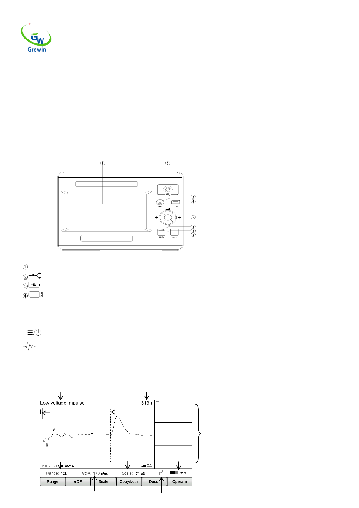
Touch screen and press key operation
-Touch operating screen with smart gesture operation
-Support cursor drag-drop function and double-click function,easy to locate
-Simple function menus with high performance.
Big color LED screen, friendly interface
-Simple function menus with high performance
7" LED screen,160°viewing angle,bright with 750cd/m2 to view under sunshine
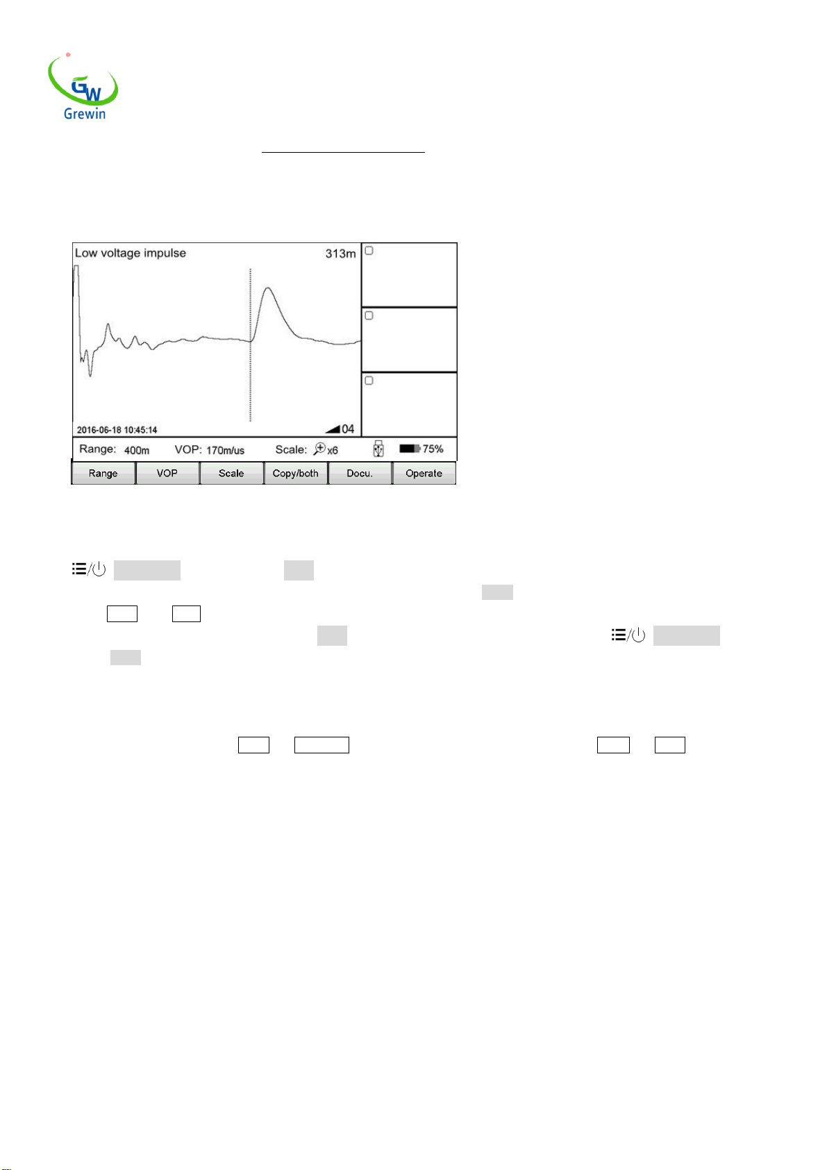
-PIP copy(pic. temporary storage). There'll be a main window and three temporary storage windows could check three waveform together.
Waveform storage and PC communication
-Special software management for software upgrade, backup and restore in device.
-Waveform storage and communication with computer.
-Internal storage of waveform.
-Optional mini printer for waveform printing

TIANJIN GREWIN TECHNOLOGY CO.,LTD.
Web:www.grewin-tech.com WhatsApp:+86-13072088960
Email:[email protected]
Address:DongLi Distr Tianjin City, China Tel: +86-22-84943756
3
-Support connection with PC or laptop
Power management
-Back light weakens if no operation in 2 min and power off in 10 min. if no operation.
-Built-in Polymer Lithium-ion battery.
-Working time could reach 7 hours for each use.
1.3 SPECIFICATION:
Locating methods:
Low voltage impulse method
Impulse current method
Multiple impulse method
Sampling frequency:
200MHz
Gain range:
0-70dB
Low voltage impulse voltage:
32V
Max.resolution:
0.4m
Locating range:
100km
Dead zone:
2m
Battery:
L-ion battery rechargeable batteries,7.4 V
endurance time over 7 hours
Communication interface:
USB,bluetooth (optional)
Power supply:
Input AC220V,50Hz,current 1A,charge for 6 hours
Dim.:
274×218×81mm
Weight:
3.5kgs
Operating Temperature:
-10℃-40℃
Humidity:
5-90%RH
Elevation:
<4500m

TIANJIN GREWIN TECHNOLOGY CO.,LTD.
Web:www.grewin-tech.com WhatsApp:+86-13072088960
Email:[email protected]
Address:DongLi Distr Tianjin City, China Tel: +86-22-84943756
4
2. PHYSICAL CHARACTERISTICS AND OPERATION
2.1 CONFIGURATION
Standard : main unit, low voltage impulse testing guideline, impulse testing connecting wire and filter,charger and so on.
2.2 MAIN UNIT PANEL
Fig.2.1 shows the operation interface
Details:
LED screen : Display all the information. Will introduce in the following.
Signal port: connect with testing wire. Choose different wires under different testing mode.
Charging port:connect with wire for built-in battery
USB disk:save or import waveform
○5 Multiple function button:total five functions,up,down,left,right and enter.Up and down button is used for gain adjustment,left and right button
is used for cursor adjustment, and enter is used to switch the dotted cursor and soiled cursor
⑥Power indicator light:it will light when power on
⑦Power/Menu : Turn on or off the machine.When power on,it's menu button.Short press into the menu,press again to exit.
⑧Test button:Press to test.
2.3 Menu introduction
This device adopts unique menu operation of the screen as fig.2.2
Fig.2.1 Operation interface
Work mode
Distance between dotted cursor and solid cursor
Testing range
Gain ,scale value
Battery level
Solid cursor
Dotted cursor
Waveform
Temporary
Window

TIANJIN GREWIN TECHNOLOGY CO.,LTD.
Web:www.grewin-tech.com WhatsApp:+86-13072088960
Email:[email protected]
Address:DongLi Distr Tianjin City, China Tel: +86-22-84943756
5
Support both touch screen operation and Mechanical button. The operation is easy, flexible and direct.
Pop-up menu operation:
Main menu includes Range,VOP,Ratio,Scaling,Copy, Staff, Docu. And Operate.
Sub-menu will pop-up when press above button. After operation or click other position of the screen will exit sub-menu.
Press Power/Menu or Sub-menu will enter the menu mode,and now user could use the multiple function button to operate.
Press Power/Menu again to exit.
Below is the introduction of main-menu button and their sub-menu details:
*Operation example:
Observe the waveform,seems the fault point may located on the first half of the waveform,so the distance 1.5km range is too large and then adjust
the distance to 400m.
Touch operation as below:
Click Range button displayed the optional range.Click 400m button, exit after chosen. Now the range change into 400m as in below fig.4.The device
Main menu
Submenu
Range
200m、400m、800m、1.5km、3km、6km、12km、25km、50km、100km
VOP
XLPE cable,oil paper cable,plastic cable,VOP+,VOP-
Scale
Global,zoom in,zoom out
Copy
1/2/3 zone copy,1/2/3 zone compare
Staff
Scale switch,new staff,contact setting,fault setting,full
length setting,contact delete
Docu.
Local storage,USB disk storage,main unit to USB,docu.recall
Operate
system setting,screen correct
Fig.2.2 Working interface
Waveform velocity value
USB indication

TIANJIN GREWIN TECHNOLOGY CO.,LTD.
Web:www.grewin-tech.com WhatsApp:+86-13072088960
Email:[email protected]
Address:DongLi Distr Tianjin City, China Tel: +86-22-84943756
6
auto test again after modify the range. The testing waveform as below Fig.2.4
Mechanical button operation as below:
Click Power/Menu button to enter the Menu mode. Current menu will highlight in the main menu and automatically appear pop-up
sub-menu. Use the multiple function button Left/Right button to choose main menu as Range ,and use the Up/Down button to choose the
sub-menu as 400m. Press Enter button to change the range as 400m and automatically exit the sub-menu. Check the testing range, it’s 400m so
the modify is successful and will automatically exit the Menu mode. If no execution any sub-menu and click the Power/Menu button again,
it will exit the Menu mode.
Summing up above points, menu operation steps are as below:
- choose the main menu, and press the corresponding sub-menu
- choose the sub-menu, and press the corresponding button
In the following,we will all use the way Menu —sub-menu to introduce the operation steps.(For example, Range —200m)
2.4 Basic operation
2.4.1 Choose the testing range
Testing range is the device measuring distance.
For TDRL or ARM(multiple impulse method):
For the initial testing, the range should be hundreds meters longer than the cable complete length, for example,if the cable is 1400m, it’s suggested
to choose 3000m but no 1500m. If the suspect point is close, it is suggest to reduce the testing range.
For Impulse current mode:
When initial testing,the range should be triple of the cable length. For example, if the cable is 200m, it is suggested to choose 800m.If the suspect
point is close, it is suggest to reduce the testing range.
For testing range chosen:
Choose Range menu to choose different range, total 10 levels from min. 200m to max. 100km,refer below Fig. 2.5
Fig.2.4 Working interface

TIANJIN GREWIN TECHNOLOGY CO.,LTD.
Web:www.grewin-tech.com WhatsApp:+86-13072088960
Email:[email protected]
Address:DongLi Distr Tianjin City, China Tel: +86-22-84943756
7
2.4.2 Adjust the waveform
Device adopts the traveling wave method to do fault locating.
Through VOP menu to set and adjust wave velocity. Refer Fig.2.6.
Steps:
Chick the VOP menu and choose different waveform velocity or directly to adjust the velocity to a suitable value.
Cross linked(XLPE): Cross linked polyethylene cable,170m/us
Oil paper: Impregnated paper insulated cable,160m/us
Plastic: Plastic cable,201m/us
Robber: Robber cable,220m/us
Use the VOP + & VOP - button to adjust the velocity. Under this interface,if click VOP + or VOP - button,the sub-menu can’t automatically
disappear. Click VOP button or other screen position, the sub-menu will automatically disappear.
Fig.2.5 Range chosen interface
Fig.2.6 Waveform velocity adjustment

TIANJIN GREWIN TECHNOLOGY CO.,LTD.
Web:www.grewin-tech.com WhatsApp:+86-13072088960
Email:[email protected]
Address:DongLi Distr Tianjin City, China Tel: +86-22-84943756
8
2.4.3 Scale operation
If need to check the waveform velocity details, and analysis the waveform, we could choose the scale operation to scale and check the details.
Chose the main menu Scale and to zoom in/out as shown in Fig.2.7
Steps:
Choose Scale menu,then choose Full extent, Zoom in or Zoom out
Full extent restore the complete waveform
Zoom out zoom out and display part of the waveform centered on dotted cursor. Move the dotted cursor to left/right and it will automatically
page turning when reach the border.
Zoom in zoom in and display part of the waveform centered on dotted cursor. Move the dotted cursor to left/right and it will automatically page
turning when reach the border.
2.4.4 Copy/both operation
If need to compare the waveform, it is suggested to use the the Copy/both button.The device could temporarily storage 3 waveform and display the
waveform in the Copy Window. Refer Fig. 2.8
*ICM (impulse current mode) doesn’t have this function
Sub-menu introduction:
zone 1 copy:Temporary storage the waveform in window 1 on the right.Other copy buttons are similar function.
zone 1 Both:Display the waveform of window 1 into the main window.Other both buttons are similar function.
Fig.2.7 Scale operation

TIANJIN GREWIN TECHNOLOGY CO.,LTD.
Web:www.grewin-tech.com WhatsApp:+86-13072088960
Email:[email protected]
Address:DongLi Distr Tianjin City, China Tel: +86-22-84943756
9
Touch operation:
Through slide special shapes in the screen,device will distinguish different functions.The shapes of waveform copy and waveform both function are
below shapes in the pic.
Zone 1 copy: Sliding from main window to the Zone 1.
Zone 1 both: Sliding from Zone 1 to the main window.
Other operations are same.Sliding again to exit the compare..
Double click the Copy windows to compare the waveform or exit the comparing.
Fig.2.8 Copy/ both button introduction
Fig.2.9 Copy/ both touch operation

TIANJIN GREWIN TECHNOLOGY CO.,LTD.
Web:www.grewin-tech.com WhatsApp:+86-13072088960
Email:[email protected]
Address:DongLi Distr Tianjin City, China Tel: +86-22-84943756
10
2.4.5 Docu. Operation
Different methods will be for waveform management.
Choose the Docu.,the operation as below Fig.2.10
Button introduction as below:
Internal: Storage the wave in the device. The stored file name is default as 'working mode English abbreviation & wave storage date.All are xxx.wav
file
Low voltage impulse mode: TDR
Impulse current mode: ICM
Multiple impulse mode: ARM
USB: save the data into the USB disk.
I to U: insert the USB disk into the USB port. Click this button to export data to USB
Recall: Open the waveform file stored in the device. Click this button to appear the file windows as below Fig. 2.11
Button introduction as below:
Enter: highlight the chosen waveform and the waveform will display in he main windows
Cancel: cancel operation or exit from this file window
Delete: delete the chosen file and press ↓↑ to choose file. After click it, the prompt information will appear.
Clear: clean the waveform file in the device(can’t be restored)
Fig.2.10 Docu. operation
Fig.2.11 Recall waveform file

TIANJIN GREWIN TECHNOLOGY CO.,LTD.
Web:www.grewin-tech.com WhatsApp:+86-13072088960
Email:[email protected]
Address:DongLi Distr Tianjin City, China Tel: +86-22-84943756
11
Internal file: choose the files stored in the device
USB file: Chose the files stored in the USB disk, valid when insert the USB disk
USB usage: indicates the files storage in the device. If reach 100%, new waveform can’t be logged. Delete old waveform before store new
waveform.
2.4.6 Parameter setting
Operate below steps:
Operate —System setting, pope window appears as below Fig.2.12
It’s for impulse current delay setting, multiple impulse delay and date setting.
Steps as below:
Click the parameters need to modify
Use the number keyboard to modify the parameter value
Click the OK to confirm the modify
2.4.7 Delay adjustment
When use the impulse current mode and the multiple impulse mode to test, it is needed to adjust the delay. Details refer following captor.
2.4.8 Exit testing
When use the impulse current mode and the multiple impulse mode to test, press Test button to enter the triggering condition. Press this
button again to exit.
2.4.9 Waveform movement
Move the cursor to the left end of the waveform, then continue to move to the left, the waveform will move to right for half screen. Similar as in
the right operation.
2.4.10 Cursor movement
Under the normal mode, move the cursor position through ○5 Multiple function button.
Left and right button is used for cursor movement.
Long time press to move fastly, short time press to pinpointing.
Fig.2.12 System setting windows introduction

TIANJIN GREWIN TECHNOLOGY CO.,LTD.
Web:www.grewin-tech.com WhatsApp:+86-13072088960
Email:[email protected]
Address:DongLi Distr Tianjin City, China Tel: +86-22-84943756
12
2.4.11 Cursor movement operation (touch operation)
Use the stylus to press the cursor, drag the cursor to suitable position. Or double click the target position by stylus, the dotted cursor will move this
position.
Or use touch screen to roughly position. And then pinpointing by the multiple button.
2.4.12 Data setting
Date is the retrieval tag of stored waveform, so it’s important to make sure the device time is correct. If there’s error,it’s needed to set again. Steps
as below:
Choose Operate —System setting to set the data in the pop-up window. Refer Fig.2.12
2.4.13 fault distinguish and work mode selection.
Before distance locating, we should first judge the cable fault to choose the suitable detecting method, steps as below:
Use tramegger to measure the insulation resistance of each phase -earth and phase-phase of cable terminal. If the tested result is 0, to use the
multimeter to test resistance again. If the tested result is very high, reach normal insulation level, check whether cable is break by method: short
circuit three phase and short circuit to the earth in one end of cable, then test in another end of cable to distinguish whether it’s break.
Fault tyoe and the distinguish method as below
No
Cable Fault
Representation
Testing method
1
Low resistance
/short circuit fault
Tramegger value :0
Multimeter value:< 200Ω
Low Voltage Impulse
2
Break fault
Conductor disconnection
Low Voltage Impulse
3
High resistance
fault
Tramegger :0
Or:
Tramegger :0
Multimeter:≥200Ω
Impulse current
4
Flashover fault
Tramegger: insulation normal
Withstand voltage test:no
Adopt different testing methods, different testing connection lines are needed.
The work mode of generator also need to adjust, our HVSG-500GX device could recognize different signal sources and automatically adjust the
working mode.
During different working mode, the operation menu has different function, in the following chapters, we'll give a detailed introduction.
2.4.14 Touch screen calibration
During the usage,if find touch position is not accuracy, it is needed to do screen calibration. Click Operate —screen correction ,refer below
Fig.2.13

TIANJIN GREWIN TECHNOLOGY CO.,LTD.
Web:www.grewin-tech.com WhatsApp:+86-13072088960
Email:[email protected]
Address:DongLi Distr Tianjin City, China Tel: +86-22-84943756
13
Fig.2.13 Screen correction
Table of contents
Other GREWIN Safety Equipment manuals