Web:www.grewin-tech.com .WhatsApp/Tel:+86-13072088960
Add:DongLi Distr Tianjin City, China Email:salesmanager@grewin-tech.com
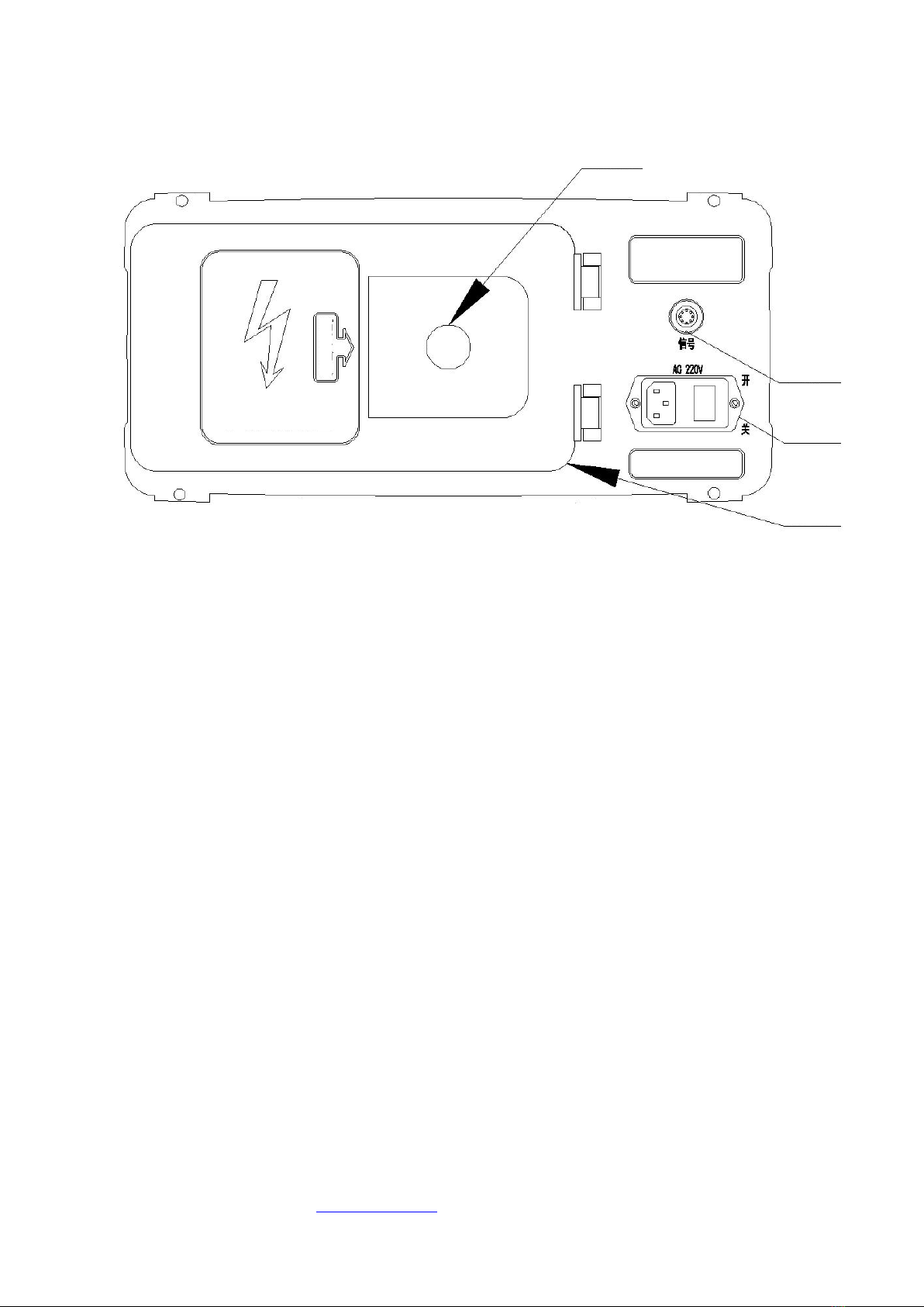
2. Front panel
Figure2. Operation panel
1.Power port: Working power supply, AC 220V,50Hz
2.Signal port: connect with the pre-locator signal port
3.Power indicator: When power on,the power indicator bright
4.High voltage input: Connect with high voltage signal generator,such as our HVSG-500GN generator.
Pls notice, the input voltage should no high than 35kV.The impact energy is below 2000J.Otherwise,the
device may be destroyed if too high surge voltage and large surge energy.
5.High voltage output: Connect the high voltage output line of the target cable. Apply high voltage signal
and the multi impulse signal to the target cable. The red clip is negative high voltage output. The black
clip is the test grounding.
When phase-sheath fault, the black clip connected with the sheath and read clip connect with the faulty
core. When phase-phase fault, the black clip connect with the two faulty cores.
When high voltage generator work,away from the output clamp.After use,pls release before wire apart.
NOT MISTAKE THE POLARITY OTHERWISE THE DEVICE WILL BE DESTROIED
6.protect grounding: it is the device protect point and must well grounding.