Greyline AVFM 5.0 User manual

www.greyline.com
USER'S GUIDE
Installation & Operation
Instructions
Area-Velocity Flow Meter
Model AVFM 5.0
Manual Series A.2.3

Note: This page has been left blank intentionally.

Page 3
AVFM 5.0 Area-Velocity Flow Meter
INDEX
CONNECTIONS ................................................................................................4
FUNCTION TEST..............................................................................................4
KEYPAD SYSTEM............................................................................................6
CALIBRATION MENU.....................................................................................7
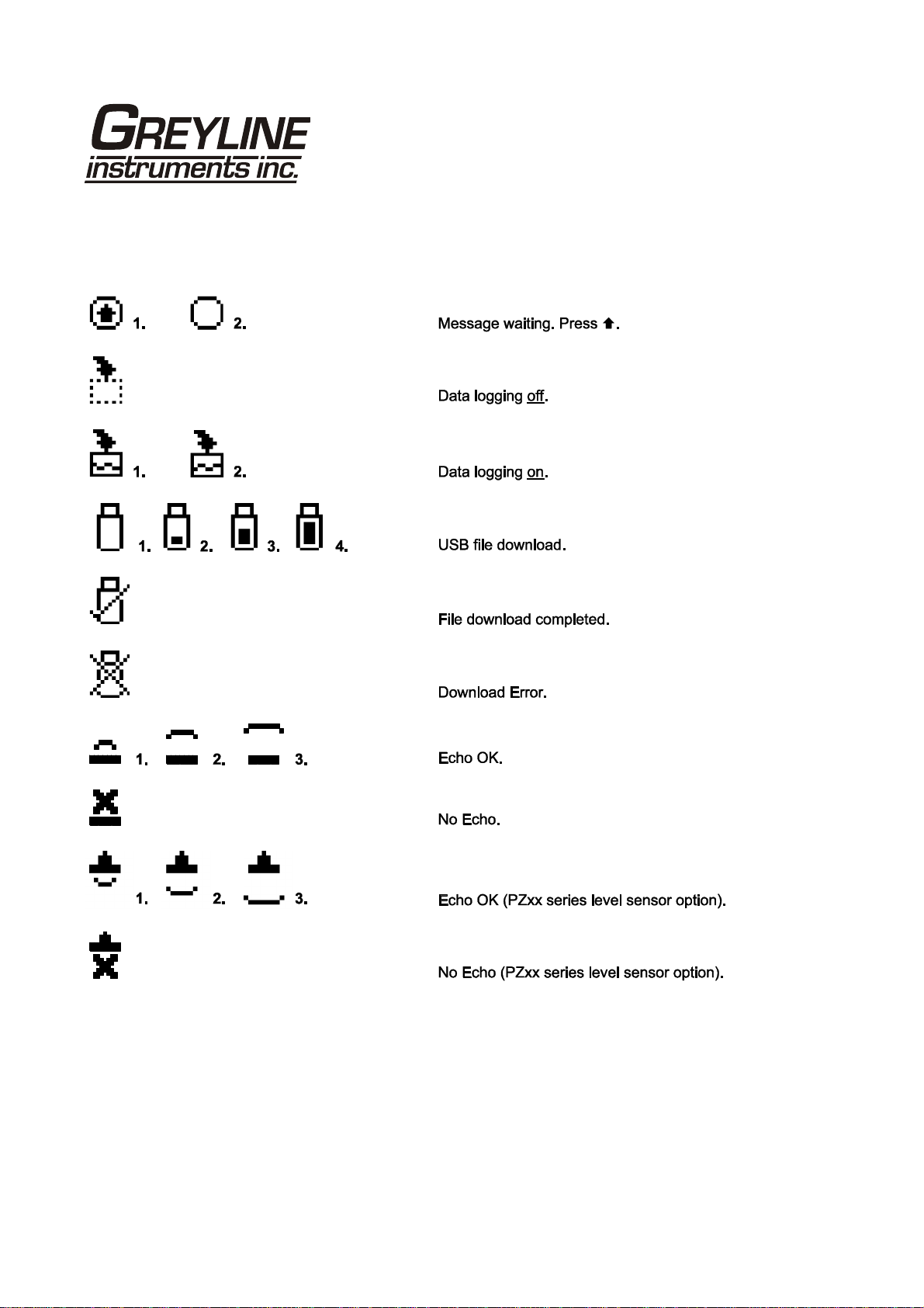
ICONS.................................................................................................................8
MESSAGE ICON ...............................................................................................9
STATUS..............................................................................................................9
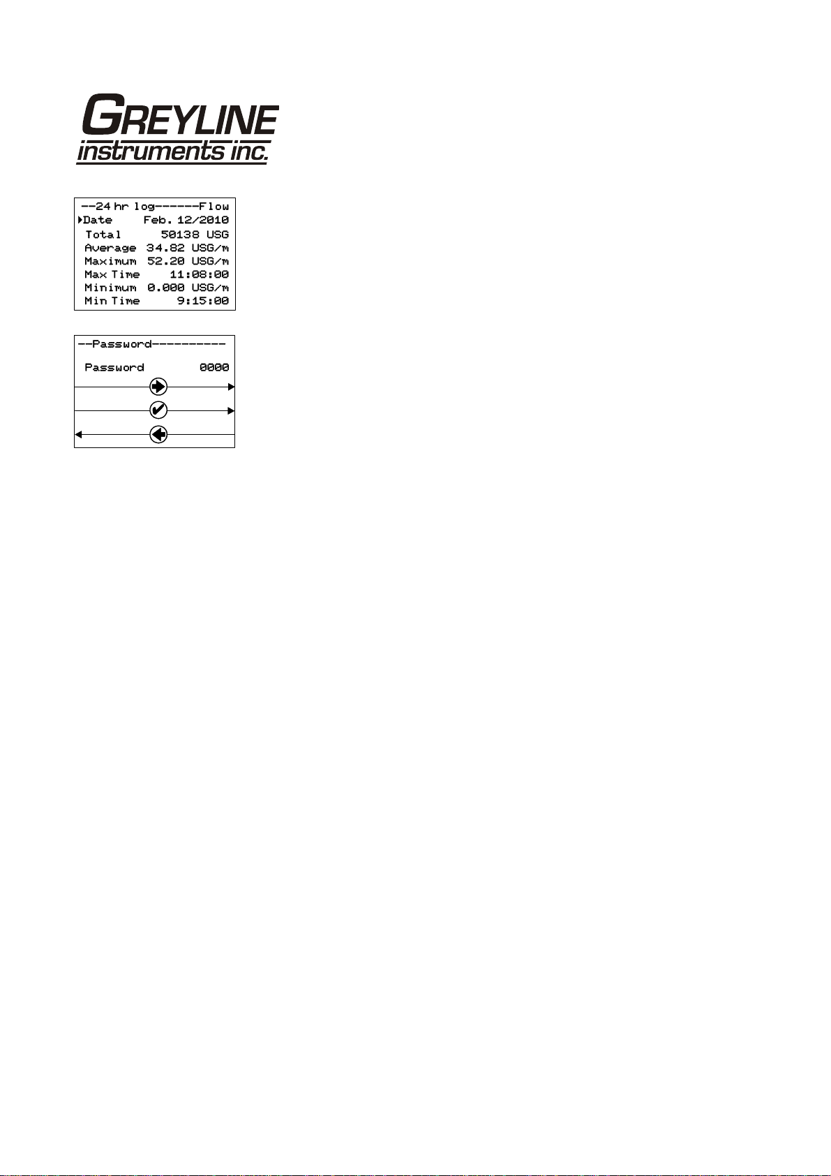
PASSWORD.....................................................................................................10
UNITS/MODE..................................................................................................11
CALIBRATION................................................................................................12
RELAY PARAMETERS..................................................................................16
SPECIAL FUNCTIONS...................................................................................17
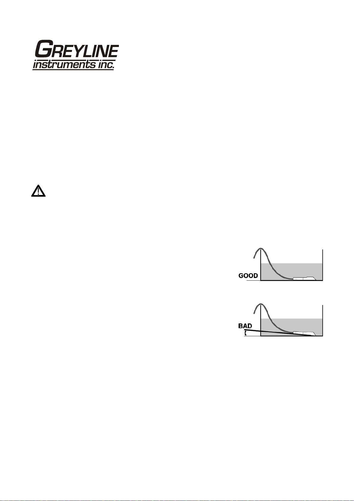
INSTALLATION - SENSOR LOCATION......................................................19
ENCLOSURE INSTALLATION.....................................................................23
FIELD TROUBLESHOOTING........................................................................25
APPLICATIONS HOTLINE............................................................................27
PRODUCT RETURN PROCEDURE...............................................................28
AREA-VELOCITY FLOW DATA SHEET .....................................................29
APPENDIX A – OPTIONS...............................................................................31
DATA LOGGING (OPTIONAL).........................................................................39
SPECIFICATIONS...........................................................................................41
IMPORTANT NOTE: This instrument is manufactured and calibrated to meet product specifications.
Please read this manual carefully before installation and operation. Any unauthorized repairs or
modifications may result in a suspension of the warranty.
Available in Adobe Acrobat pdf format

Page 4
AVFM 5.0 Area-Velocity Flow Meter
CONNECTIONS
POWER INPUT: 100 to 240 VAC 50/60Hz. No adjustments are necessary for voltages within this
range. Connect L (Live) N (Neutral) and AC Ground.
Optional DC: 9-32 VDC. Connect to + and - terminals.
Optional Thermostat and Heater modules are available rated for 115 VAC or 230 VAC.
IMPORTANT NOTE: To comply with CSA/UL electrical safety standards, AC power input and relay
connection wires must have conduit entry to the instrument enclosure. Installation requires a switch,
overcurrent fuse or circuit breaker in the building (in close proximity to the equipment) that is marked as
the disconnect switch.
Risk of electric shock. Loosen cover screw to access connections. Only qualified personnel
should access connections.
Note: Use of instrumentation over 40°C ambient requires special field wiring.
Note: User replaceable fuse is 2 Amp 250V (T2AL250V).
FUNCTION TEST:
Connect the sensor to the sensor terminals as shown on next page, then
apply power. Allow 30 seconds for the AVFM 5.0 to initialize.
A. Place QZ02L sensor (flat to the bottom) in a bucket of water
about 6” deep and select Level mode (from UNITS/MODE
menu) to see a level reading.
B. Select Velocity mode and stir the water to see a velocity
reading.

Page 5
AVFM 5.0 Area-Velocity Flow Meter
CONNECTIONS

Page 6
AVFM 5.0 Area-Velocity Flow Meter
KEYPAD SYSTEM
The AVFM 5.0 uses a menu system. Arrows show the four directions to leave a menu box. Pressing a
corresponding keypad arrow will move to the next item in the direction shown. Move the cursor
(underline) under numerals and increase or decrease numerals with the and keys.
To store calibration values permanently (even through power interruptions), press .

Page 7
AVFM 5.0 Area-Velocity Flow Meter
CALIBRATION MENU

Page 8
AVFM 5.0 Area-Velocity Flow Meter
ICONS

Page 9
AVFM 5.0 Area-Velocity Flow Meter
MAIN DISPLAY
The main display shows the units selected from the Units/Mode menu, Flow or
Velocity rate being measured, TOTALIZER and RELAY states. The AVFM 5.0
will start-up with this display.
MESSAGE ICON
Press from the main display to view temperature measurement, status of the
data logger and error/warning messages provided by the instrument. The
Message Icon will appear on the main display if error messages are being
generated by the instrument. Press to return to the main display.
STATUS
Press from the MAIN display to view instrument status.
Velocity Will be displayed in ft/sec or m/sec.
Level Is displayed in the selected units.
Tot Displays the current totalizer reading.
Signal Cutoff Adjust the setting in percent to suppress flow readings
at zero flow when fluid swirling or pipe vibration may
cause the instrument to continue reading. Example:
Signal Cutoff at 5% will force the display and
outputs to zero when signal strength drops below 5%.
Signal Strength Displays percentage of signal being received by the
ultrasonic sensor.
EC Displays level measurement Echo Confidence
Relays 1 2 3 4 5 6 Energized relays will display with reversed font eg:

Page 10
AVFM 5.0 Area-Velocity Flow Meter
24 HR LOG (Data Logging option only)
Press from the MAIN display to view a formatted flow report from instruments
with a built-in data logger. Press to pan through Level,Velocity and Flow
summaries. Press to scroll down one day or repeatedly to scroll to a specific
date. Up to 365 days can be stored. Newest date will overwrite the oldest. Press
to return to the main display.
PASSWORD
The Password (a number from 0000 to 9999) prevents unauthorized access to
the Calibration menu.
From the Main display press to get to Password. Factory default password is
0000 and if it has not been changed press to proceed to the Menu Selections
screen.
If a password is required, press to place the cursor under the first digit and or
to set the number, then to the second digit, etc. Press or to proceed to
the Menu Selections screen.
A new password can be stored by going to Special Functions/New Password.

Page 11
AVFM 5.0 Area-Velocity Flow Meter
UNITS/MODE
From Mode press the and then the or to select Flow,Velocity or
Level. Flow mode displays the flow rate in engineering units (e.g. gpm, litres/sec,
etc.) Press the to store your selection then the to the next menu item.
From Linear press the key and then the or to select your units of
measurement. Press the to store your selection.
Press the key to move the symbol to each subsequent menu item and the to
save your selections.
Note: the volume selection "bbl" denotes U.S. barrels.
Temperature press then to select Cor F.
Press or to return to the Menu Selections screen.

Page 12
AVFM 5.0 Area-Velocity Flow Meter
CALIBRATION
Press to Calibration and to enter. Use or to position before each
menu item and to enter. When settings are completed press to store and
return to the Calibration menu.
20mA Flo
[5V Flo]
Press
and enter the
flow rate
value for 20mA.
Note
:
Analogue output can be selected as 4
-
20mA or 0
-
5V in Special Functions.
4mA Flo
[0V Flo]
Press
and enter the
flow rate
value for 4mA.
20mA Vel
[5V Vel]
Press
and enter the
velocity
value for 20mA.
4mA Vel
[0V Vel]
Press
and enter the
velocity
value for 4mA.
20mA Level
[5V Level]
Optional for QZ02L
-
A type
sensor
. Press
and enter the
level
value for 20mA.
4mA Level
[0V Level]
Optional for QZ02L
-
A type
sensor
. Press
and enter the
level
value for 4mA.
MaxRg
Only
for
PZ15
LP/QZ02L
-
B type
sensor
. Press
and enter the
zero water level (distance from the PZ15-LP sensor to the zero
water level).
MinRg
Only
for
PZ15
LP/QZ02L
-
B type
sensor
. Press
and enter
the
max level (distance from the PZ15-LP sensor to the max water
level).
Min Level
Optional for QZ02L
-
A type
sensor
. Press
and enter a
minimum level cutoff. Level reading less than Min Level will
be forced to zero.

Page 13
AVFM 5.0 Area-Velocity Flow Meter
Lvl Offset
Optional
f
or QZ02L
-
A
type
sensor
. Press
and enter
an
offset to level measurement. Set to 0.00 when sensor mounted
on floor of channel. When sensor is mounted above the floor
of the channel enter the distance between channel floor and
bottom of sensor. Maximum offset is ± 36” (914 mm).
Note:
4mA is not affected by
Lvl Offset
settings. 4mA is the
bottom of the channel or pipe.
Min Vel
Press
and enter a minimum velocity cutoff. Forward and
reverse velocities less than Min Vel will be forced to zero.
Damping
Increase
damping to stabilize readings under turbulent flow
readings or to reject spurious level readings. Decrease for
faster response to changes in flow.
Press
from the
Calibration
display to return to Menu Selections.

Page 14
AVFM 5.0 Area-Velocity Flow Meter
CHANNEL SETUP
Round Select Round for open pipes. Set Max Height to the inner
diameter of the pipe.
Rectangle Select Rectangle for rectangular channels. Enter the channel
width.
Trapezoid Select Trapezoid for trapezoidal shaped channels. Specify the
Width and Slope of the channel as shown in the following
illustration.
Egg Select Egg for Egg shaped channels. Enter the Max Height
of the channel.

Page 15
AVFM 5.0 Area-Velocity Flow Meter
CUSTOM CHANNELS
Reset Data Old data MUST be removed before entering data for a new
channel. Press then press to Yes and press to clear
old data.
Max Height Enter the maximum height of the channel.
Division Divide the maximum height into equal increments (maximum
of 40) and enter this division value (example 1”, 1 cm etc.)
Increment # Enter the increment number if you want to edit a previous
entry or to skip entering widths for some levels (Note: The
custom channel will interpolate widths between entry points).
Width Enter the measured width of the channel at the level shown
(Note: To enter 0 width you must press and then to store
a 0 width data point).
Level Displays the level of the channel for each increment and width
entry.
Note
:
Custom channel data in equal width increments with variable height
measurements must be converted to the format shown above using the “Channel
Data Translator” PC software.

Page 16
AVFM 5.0 Area-Velocity Flow Meter
RELAY PARAMETERS
Relay Press and or to select a relay (2 relays are standard, 4
additional are optional).
Function Press or to select Off,Pulse,Flow,Velocity or
Level.
Flow
On Position the cursor under the numerals and press or to set
digits to the relay On set point.
Off set digits to the Off set point.
Pulse Press and set digits to the flow volume per relay pulse. Use
this feature for remote samplers, chlorinators or totalizers.
Minimum time between pulses is 2.25 seconds and pulse
duration is 350 milliseconds.
Return to Relay and enter settings for each relay.
Velocity
On Position the cursor under the numerals and press or to set
digits to the relay On set point.
Off set digits to the Off set point.
Level
On Position the cursor under the numerals and press or to set
digits to the relay On set point.
Off set digits to the Off set point.
LOE mode Specify the state of the relay for loss of echo condition:
Off,On or Hold.
Press to return to Menu Selections

Page 17
AVFM 5.0 Area-Velocity Flow Meter
DATA LOGGING (OPTIONAL)
Refer to Options section of this manual.
SPECIAL FUNCTIONS
Language Select English,French or Spanish
Analog Out Select 4-20mA or 0-5V mode for the analog output.
Backlight Select High,Medium or Low for continuous
backlight.
Select Key Hi/Lo for high backlight (for 1 minute)
after a keypress and then Lo backlight until a key is
pressed again.
Select Key High,Med or Low for backlight after a
keypress and then backlight off until a key is pressed
again.
Reset Totalizer Press and select Yes to erase and restart the
totalizer at zero.
Negative Totals Select Yes to have reverse flow readings deducted
from the totalizer. Select No to totalize forward flow
only and ignore reverse flow.
Flo Direction Select On to enable flow direction measurement.
Select Off to disable flow direction measurement so
that flow in either direction is displayed and output as
positive values.
Select Invert to invert the sense of the flow
measurement.
Cal Constant Scales the velocity reading. Set to 1.000 for QZ02L
sensor.
Restore Defaults Select Yes and press to erase all user settings and
return the instrument to factory default settings.
New Password Select any number from 0000 to 9999 and press .
Default setting of 0000 will allow direct access to the
calibration menus. Setting of any password greater than
0000 will require the password to be entered to access
the calibration menus.
Press to return to Menu Selections.

Page 18
AVFM 5.0 Area-Velocity Flow Meter
SIMULATION
Exercises the 4-20mA (0-5V) outputs, digital display and control relays.
Test Select Maximum and press to simulate maximum Flow, Level and
Velocity and to output 20mA (5V) to the analog channels.
Select Minimum and press to simulate minimum Flow, Level and
Velocity and to output 4mA (0V) to the analog channels.
To simulate an intermediate Flow, Level and Velocity set Test to
Actual and then enter a value for the Level and Velocity. The Flow
calculation, analog outputs and control relays will respond to the
simulated values.

Page 19
AVFM 5.0 Area-Velocity Flow Meter
INSTALLATION - SENSOR LOCATION
1. Choose a sensor mounting location where silt or deposits are least likely to accumulate.
2. For best results flow should be evenly distributed across the channel and relatively free of turbulence.
(The AVFM 5.0 is very effective at averaging level and velocity readings in turbulent conditions, but
best accuracy and response time is achieved with evenly distributed flow.)
3. Avoid vertical drops, obstructions or elbows immediately up and downstream from the sensor. Locate
the QZ02L sensor at least 10 times maximum Head (level) and 10 times the channel width from these
flow disturbances.
4. The QZ02L submerged level-velocity sensor requires a minimum water level of 1 in. (25.4 mm).
QZ02L VELOCITY-LEVEL SENSOR MOUNTING
Mount the QZ02L sensor with the
stainless steel bracket and hardware
supplied. Ensure that the sensor is
parallel to the water surface (check with
a level). Mount with the tapered end of
the sensor pointing upstream and the
sensor cable pointing downstream.
Clip or tie wrap the sensor cable securely
to the pipe or channel wall.
Note: The mounting bracket is designed
to release the sensor if weeds or rags are
caught by the sensor.

Page 20
AVFM 5.0 Area-Velocity Flow Meter
Table of contents
Other Greyline Measuring Instrument manuals
Popular Measuring Instrument manuals by other brands

BW Technologies
BW Technologies GasAlert MicroClip XT Operator's manual

Leuze electronic
Leuze electronic AMS 348i SSI Original operating instructions

Sam
Sam FL-12 operating instructions

Vision & Control
Vision & Control TOB42/11.0-185-F10-WN Instructions for use

Quensus
Quensus LeakNet user manual

Trotec
Trotec BX09 operating manual

Sony
Sony DK812FR instruction manual

Hioki
Hioki 3196 Quick start manual

OXTS
OXTS Survey+ v3 user manual

Kuntze
Kuntze Krypton Neon DIS Installation and setup guide

Photon Systems Instruments
Photon Systems Instruments N-Pen N 110 Manual and user guide

PCE Health and Fitness
PCE Health and Fitness GM 55 user manual