Greyline ISM 5.0 User manual

www.greyline.com
USER'S GUIDE
Installation & Operation
Instructions
Insertion Magmeter
Model ISM 5.0
Manual Series 1.2

Note: This page has been left blank intentionally.

ISM 5.0 INSERTION MAGMETER
Installation and Operation Guide
www.greyline.com

Page 2
SAFETY INFORMATION
This meter was calibrated at the factory before shipment. To ensure correct use of the meter, please read
this manual thoroughly.
Regarding this Manual:
•
This manual should be passed on to the end user.
•
Before use, read this manual thoroughly to comprehend its contents.
•
The contents of this manual may be changed without prior notice.
•
All rights reserved. No part of this manual may be reproduced in any form without
GREYLINE’s written permission.
•
GREYLINE makes no warranty of any kind with regard to this material, including, but
not limited to, implied warranties of merchantability and suitability for a particular
purpose.
•
All reasonable effort has been made to ensure the accuracy of the contents of this manual.
However, if any errors are found, please inform GREYLINE.
•
GREYLINE assumes no responsibilities for this product except as stated in the warranty.
•
If the customer or any third party is harmed by the use of this product, GREYLINE
assumes no responsibility for any such harm owing to any defects in the product which
were not predictable, or for any indirect damages.
Safety Precautions:
The following general safety precautions must be observed during all phases of installation,
operation, service, and repair of this product. Failure to comply with these precautions or with
specific WARNINGS given elsewhere in this manual violates safety standards of design,
manufacture, and intended use of the product. GREYLINE Instruments assumes no liability for the
customer’s failure to comply with these requirements. If this product is used in a manner not
specified in this manual, the protection provided by this product may be impaired.
The following symbols are used in this manual:
CAUTION
Messages identified as “Caution” contain information regarding potential damage to the
product or other ancillary products.
IMPORTANT NOTE
Messages identified as “Important Note” contain information critical to the proper operation of
the product.
WARNING
Messages identified as “Warning” contain information regarding the personal safety of
individuals involved in the installation, operation or service of this product.
!
i
!

Page 3
TABLE OF CONTENTS
1.1
INTRODUCTION ........................................................................................................................................................ 4
1.2
PURPOSE OF THIS GUIDE ..................................................................................................................... 4
1.3
TYPICAL INSERTION ELECTROMAGNETIC FLOW METER....................................................4
1.4
STANDARD FEATURES AND SPECIFICATIONS.........................................................................5
1.5
ADDITIONAL REQUIRED HARDWARE ................................................................................................. 5
1.6
ADDITIONAL HARDWARE THAT MAY BE REQUIRED ..........................................................6
1.5.1 Grounding Rings ................................................................................................................................... 6
2.1
UNPACKING ......................................................................................................................................................................... 7
2.2
CHECKING THAT YOU HAVE RECEIVED EVERYTHING .............................................................. 7
3.1
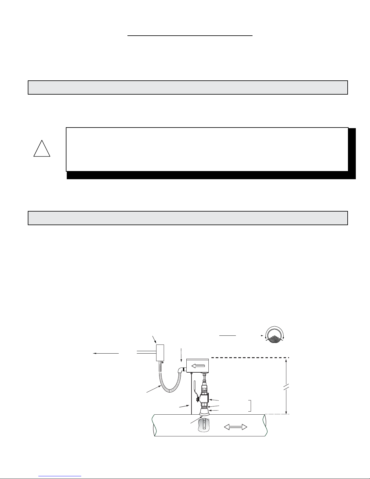
INSTALLATION, REMOVAL & ADJUSTMENT .................................................................................................8
3.2
INSTALLATION SITE SELECTION ....................................................................................................8
3.3
MECHANICAL INSTALLATION ................................................................................................................... 10
3.3.1
Installation Kit...................................................................................................................................11
3.3.2
GREYLINE Standard Installation Hardware Kit.................................................................11
3.3.3
GREYLINE Hot Tap Installation Hardware Kit ...................................................................11
3.3.4
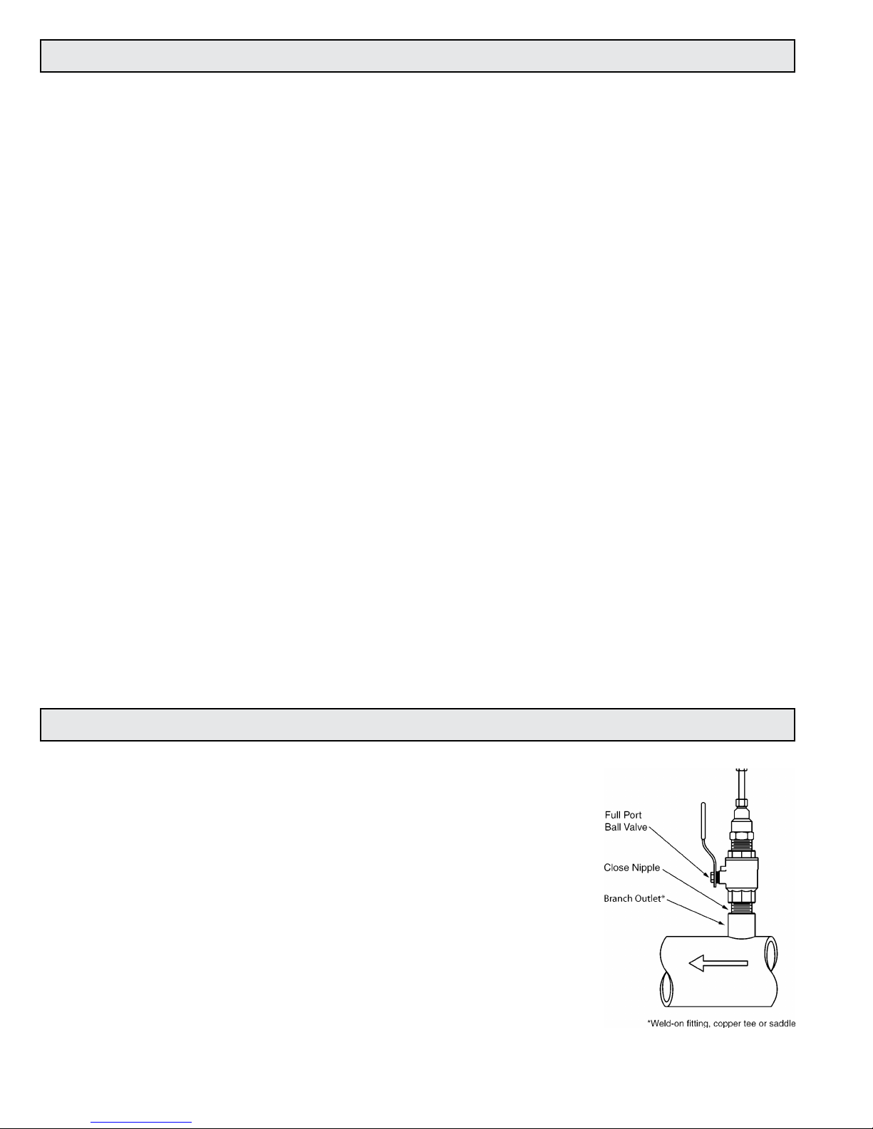
Customer Supplied Installation Hardware...........................................................................12
3.3.5
Confirming the Stack Height.......................................................................................................13
3.3.6
Installing Grounding Rings..........................................................................................................14
3.3.7
Installing the Flow Meter.............................................................................................................15
3.4
INSERTION OF THE METER.............................................................................................................. 16
3.4.1
Inserting the Flow Meter ...............................................................................................................16
REMOVAL OF THE
METER………………………………………………………………………………………………………
17
3.5
WIRING CONNECTIONS ...................................................................................................................... 18
3.5.1
Signal and Power Wiring Connections...................................................................................18
3.5.2
Earth Connection .............................................................................................................................20
4.1
START-UP & COMMISSIONIING FOR GREYLINE INSERTION
ELECTROMAGNETIC FLOW
METERS..................................................................................................................................................................... 21
4.2
HELPFUL HINTS FOR START-UP AND COMMISSIONING.................................................21
4.3
START-UP AND COMMISSIONING ................................................................................................22
4.4
START-UP AND COMMISSIONING WORKSHEET..................................................................23
4.5
TROUBLESHOOTING GUIDE ............................................................................................................. 24
4.4.1 Earth Connections & Electrical Noise Reduction.................................................................24
APPENDIX
Conditions of Sale …………………………………………………………………………………………………………………26
Applications Hotline ……………………………………………………………………………………………………………..27
Product Return Procedure …………………………………………………………………………………………………….27

Page 4
SECTION 1.0: INTRODUCTION
We, at GREYLINE Instruments, would like to thank you for purchasing our quality American made
ISM 5.0 Insertion Magmeter. As our valued customer, our commitment to you is to provide
fast
reliable service, while continuing to offer you quality products to meet your growing flow
measurement needs.
We have written this guide to provide the persons responsible for the installation, operation and
maintenance of your flow meter with the most specific equipment information they will need.
This is NOT an electrical or plumbing trade manual.
This guide is the basic reference tool for all GREYLINE ISM 5.0 Insertion Magmeters. If you
have
not purchased all of the options, there will be references in this manual which are not applicable
to your meter(s).
Faraday’s Law of electromagnetic induction states that a voltage will be induced in a conductor
when it passes through a magnetic field, and the induced voltage will be directly proportional to
the velocity of the conductor.
GREYLINE ISM 5.0 Insertion Magmeters generate pulsating magnetic fields that are used to
induce
a voltage into the conductive fluid flowing through the pipe. Electrodes located on the flow meter
sensor head measure the induced voltage. Circuitry within the flow meter electronics
enclosure
then converts the voltage to digital and analog signals that convey flow rate and total data via
connecting the cable to any of GREYLINE’s display devices, Btu meters and/or to a data
acquisition system.
Typical Meter Installation
(New construction or scheduled shutdown)
Customer provided
conduit and adapters
•
Install in vertical or horizontal pipe
•
For horizontal pipe position meter
anywhere in upper 240˚
Output signal(s)
to control
system
½" FNPT
conduit connection
Allow enough slack
in the flexible liquid-
tight conduit to
permit the meter to
be removed
from the valve.
Insertion depth
gage provided
with each meter
Standard Installation
Kit for Steel Pipe
1" Full port ball valve
1" Close nipple
1" Branch outlet
CLEARANCE
REQUIRED
FOR INSTALLATION
Typically
30" - 40"
depending on
pipe size and
height of valve
assembly.
1¼" for
hot tap
Minimum Hole Size = 1"
Must be centered
FLOW
Note: Installation kits vary based on pipe material and application. For installations in pressurized (live)
systems, use "Hot tap" 1¼ inch installation kit and drill hole using a 1 inch wet tap drill.
1.2 TYPICAL INSERTION ELECTROMAGNETICFLOWMETER
WARNING
Please do not permit persons to install, operate or maintain this equipment unless they have a
complete knowledge of their trade skills and are competent to work on high pressure hot and cold
water and steam systems, according to their individual trades. Death or permanent injury may
result from accidents with these systems.
!
1.1 PURPOSE OF THIS GUIDE
Greyline
Display or
BTU Meter
(Optional)

Page 5
Accuracy
± 1.0% of reading from 2 to 20 ft/sec
± 0.02 ft/sec below 2 ft/sec
Sensing Method
Electromagnetic, no moving parts
Pipe Size Range
3” through 72” nominal
Input Power
20 - 28 VAC 50/60Hz, 250 mA maximum
20 - 28 VDC, 250 mA maximum
Liquid Temperature Range
15° to 250° F
Ambient Temperature Range
-5° to 150° F
Operating Pressure
400 PSI maximum
Pressure Drop
Less than 0.1 psi at 12 ft/s velocity in 3” and larger pipes
Materials of Construction
Wetted metal components - 316L stainless steel
Sensor head - Polystyrene
Electronics enclosure - Powder coat painted cast aluminum
Enclosure Rating
Watertight, airtight, dust proof powder coated cast aluminum.
Electrical Connections
25’ of PVC jacketed cable with ½” NPT conduit connection
Output Signal(s)
Analog output (Isolated), selectable 4-20 mA, 0-10 V or 0-5 V
Frequency output, 0-15 V peak pulse, 0-500 Hz maximum
Scalable pulse output, isolated dry contact, contact rating 50 VDC @ 100 mA
maximum, pulse duration: 0.5, 1, 2 or 6 seconds
This product is covered by one or more of the following patents: 6,431,011 and 6,463,807.
All GREYLINE insertion type meters can be installed and removed via
a 1” or larger full port ball valve without system shutdown. The terms
“Standard” and “Hot Tap” refer to the installation method of the
isolation valve kit only.
Standard Installation Hardware: For new construction or scheduled
shutdown; once kit is installed, the flow meter can be installed
or removed without system shutdown.
Hot Tap Installation Hardware: For applications which require the
access hole in the pipe to be drilled through the valve using a
wet tap drilling machine while the hydronic system is
pressurized and operating.
NOTE: Installation hardware materials vary greatly based on pipe
material, pipe size and standard vs. hot tap versions.
1.4
ADDITIONAL REQUIRED HARDWARE
1.3 STANDARDFEATURESANDSPECIFICATIONS

Page 6
5/8
3/8
GROUNDING RING
DIMENSIONS
D
1/4
GROUNDING RING
ORDERING INFORMATION
C
Bore
1/8”
A
1.5.1
GroundingRings
Grounding rings may be required whenever meters are installed in non-metallic or lined pipes.
Grounding rings placed before and after the meter eliminate electrical noise that will interfere
with the proper operation of the meter. GREYLINE provides grounding rings as an optional
accessory. Grounding ring dimensional information and part numbers are listed below. For proper
operation, grounding rings are required before and after the meter.
Typical Installation
Non-conductive Pipe
ANSI Class 150
316 Stainless Steel
Grounding Rings (pair)
Nominal
Size
GREYLINE
Part
1”
19265
1½”
19266
2”
19267
3”
19268
4”
19269
6”
19270
8”
19271
10”
19272
12”
19273
14”
19274
16”
19275
18”
19276
20”
19277
24”
19278
30”
19279
36”
19280
42”
19281
1.5 ADDITIONAL HARDWARE THATMAYBE REQUIRED
Grounding Rings
Grounding Ring Dimensions
Nominal Size
Bore
A
C
D
1”
1 - 1/16
2 - 5/8
4 - 9/16
1 - 15/16
1.5”
1 – 9/16
3 – 3/8
5 - 5/16
1 - 15/16
2”
2 – 1/16
4 – 1/8
6 - 1/16
1 - 15/16
3”
3 – 1/16
5 – 3/8
7 - 5/16
1 - 15/16
4”
4 – 1/16
6 – 7/8
8 - 13/16
1 - 15/16
6”
6
8 – 3/4
10 - 11/16
1 - 15/16
8”
8
11
12 - 15/16
1 - 15/16
10”
9 – 1/2
13 – 3/8
15 - 5/8
2 - 1/4
12”
11 – 9/16
16 – 1/8
18 - 9/16
2 - 7/16
14”
13 – 1/2
17 – 3/4
20 - 3/8
2 - 5/8
16”
15 – 1/4
20 – 1/4
22 - 7/8
2 - 5/8
18”
17 – 3/8
21 – 5/8
24 - 1/4
2 - 5/8
20”
19
23 - 7/8
26 - 11/16
2 - 13/16
24”
23
28 – 1/4
31 - 1/8
2 - 7/8
30”
29
34 – 3/4
38
3 - 1/2
36”
35
41 – 1/4
45 - 1/4
4
42”
41
48
52 - 1/2
4 - 1/2

Page 7
SECTION 2.0: UNPACKING
GREYLINE insertion magnetic flow meters are packed and shipped in individual cartons. An optional
installation hardware kit INSTL 1 or INSTL 2, if ordered, will be packaged with each meter. All other
installation hardware and peripheral devices, including Btu meters and display modules, will be
packaged andshipped separately.
Please open all packages with care to prevent damage to their contents. Carefully inspect each item for
signs of damage in transit. The flow meter stem should be straight and free of blemishes or abrasions.
The sensor head should have a smooth continuous surface that is free of abrasions.
All GREYLINE products are shipped insured unless the customer specifically requests otherwise.
Please notify the shipping company and GREYLINE immediately if any items are damaged in transit.
Save all
packing material for inspection by the shipper.
Standard Documentation
Enclosed with each meter is a comprehensive documentation package that includes the
following items:
Installation and Operation Guide
Flow Meter Certificate of Calibration
Please notify GREYLINE if any of these documents are missing.
ISM 5.0 Insertion Magmeter Flow Meters
Optional INSTL1 or INSTL2 Installation Hardware Kit, if ordered
2.1
CHECKING THAT YOU HAVE RECEIVED EVERYTHING

Page 8
SECTION 3.0: INSTALLATION, REMOVAL AND ADJUSTMENT
GREYLINE will be happy to assist with technical recommendations and to provide guidance by
telephone or e-mail. On-site field engineering, installation and service is also available at additional cost.
Install the flow meter where it will be accessible for personnel to perform necessary periodic
maintenance. The clearance required for installation is typically 30”-40” from the pipe wall to
the nearest obstruction above the valve assembly. This clearance dimension will increase with
large diameter pipes. The environment should be free of corrosive liquids/fumes, temperature
extremes and heavy vibration. The following diagrams should be used as a guide to the proper
location for installing the meter.
GENERAL PRACTICES:
1.
For best results, install the flow meter in a straight run of pipe, free of bends,
tees, valves, transitions, and obstructions.
2.
Straight run requirements vary based on the nature of the upstream obstruction.
See the table on the following page for guidelines in determining minimum up
stream straight run requirements based on the nature of the obstruction.
Note: Depending upon specific location details, more or less straight run may be
required to produce a satisfactory flow profile.
3.
If there is insufficient straight run, allow 80% of the run upstream and 20% of the
run downstream. If the total length of straight run is less than 70% of the
recommended length, performance may seriously degrade.
IMPORTANT NOTE
Always use the maximum available straight run. When more than the minimum required
straight run is available, place the meter such that the excess straight run is upstream of the
meter location.
i
How To Determine The Available Straight Pipe Diameters:
For each application, locate the longest straight, unobstructed section of pipe (no bends, tees, valves,
other insertion probes, size transitions). The longest straight pipe run in inches divided by nominal
pipe size in inches equals “diameters of straight pipe.” For closed loop applications, consider both
the supply and return lines as possible locations.
3.1 INSTALLATIONSITESELECTION
WARNING
Insertion flow meters may be installed in pipes which are under high pressure. Accidents with
these systems can cause serious injury or death. Only persons experienced with high pressure
systems and related knowledge in the heating, cooling and fluid metering fields should attempt
to install, adjust, or remove the flow meter. Please read all instructions before attempting to
insert or remove a flow meter.
!

Page 9
•
•
For 3” and larger pipe diameters
Upstream obstruction
(A) Minimum straight run required
upstream of meter location
Single bend preceded by ≥9 diameters of straight pipe
10 Diameters
Pipe size reduction / expansion in straight pipe run
10 Diameters
Single bend preceded by ≤9 diameters of straight pipe
15 Diameters
Outflowing tee / Pump outflow
20 Diameters
Multiple bends out of plane
30 Diameters
Inflowing tee
30 Diameters
Control / Modulating valve
30 Diameters
Installation with Grounding Rings
with Non-conductive Pipe
Gaskets (4 pl)
5 DIA
*
10 DIA
Grounding Rings (2pl)
* Additional straight run may be required upstream of the upstream grounding ring based on the nature of
the upstream obstruction. Refer to the chart above to determine how much straight run is required.
Acceptable to install in vertical pipe
Position
meter anywhere in upper 240°
for horizontal pipe
CLEARANCE
REQUIRED
FOR INSTALLATION
30” - 40”
(76 - 100 cm)
Depending on
pipe size
5 Dia.
A
Available Straight Run*

Page 10
GREYLINE Insertion Electromagnetic Flow Meters employ a hot tap adapter design that allows
for
insertion and removal, when necessary, without interrupting flow and draining the pipe. To
take
advantage of this feature, the flow meter must be installed through an isolation valve. The
installation must allow for sufficient overhead clearance to fully extract the meter, and a full 1”
opening in the pipe wall is required to clear the sensor head and allow for insertion. Make sure
that your valves and fittings are full port and at least 1” in actual internal diameter.
IMPORTANT NOTE
Flow meters installed through oversized access holes will be subjected to undesirable turbulence
that may affect the accuracy of the meter.
i
CAUTION
GREYLINE insertion style flow meters must be installed through a valve assembly. Failure to do
so negates the ability to remove the meter without shutting down and draining the system. It
will
also result in an excessive amount of stem protruding from the pipe. Excessive stem lengths
unnecessarily expose the meter to incidental damage.
!
CLEARANCE
REQUIRED
FOR
INSTALLATION
Typically
30" - 40"
depending on
pipe size and
height of valve
assembly.
Standard Installation
Kit
for Steel Pipe
1"
Full port ball valve
1"
Close nipple 1¼"
for
hot
tap
1" Branch outlet
Minimum Hole Size = 1"
Must be centered
NOTE: Use stainless steel or brass
close nipple only.
3.2
MECHANICAL INSTALLATION

Page 11
3.2.1
Installation Kit
GREYLINE offers a wide range of installation hardware kits for commonly used pipe
materials. The kits are specifically designed for GREYLINE flow meters, and their use is
recommended.
The use of GREYLINE installation hardware kits accomplishes two important objectives.
First, it ensures that the proper hardware is used. Second, it simplifies order processing
by standardizing the dimensions of the installation hardware. GREYLINE must have an
accurate measurement of the overall height of the installation hardware as measured from
the outside wall of the pipe to the top of the valve in order to determine the correct stem
length when assembling the meter in our factory. GREYLINE documents refer to this
dimension as the stack height.
GREYLINE installation hardware kits consist of three separate component parts:
And a full port
isolation valve.
Different pipe materials require different branch outlets and may include additional
bushings to properly size the opening.
3.2.2
GREYLINE Standard Installation Hardware Kit
Standard installation hardware kits are designed to be installed on piping systems that
are drained and at atmospheric pressure. The access hole is drilled (1” minimum) prior
to installation of the branch outlet with 1” NPT threads, close nipple and full port ball
valve. Once the isolation valve is installed, the piping system can be flushed, filled and
pressurized. The flow meter may now be inserted or removed by hand without having to
drain the system. Please read all instructions before proceeding with meter insertion.
3.2.3
GREYLINE Hot Tap Installation Hardware Kit
GREYLINE offers an alternative installation hardware kit when it is not practical to
relieve
pressure and drain the system. In this case, a 1¼” branch outlet, close nipple and
1¼” full
port ball valve are installed first. Then, a hot tap drilling apparatus is used to drill
a 1”
diameter hole through the valve. This eliminates the need to shut down and drain the
pipe. Please read all instructions before proceeding with meter insertion.
Some type of
threaded branch
outlet,
An
interconnecting
close nipple,

Page 12
3.2.4
Customer Supplied Installation Hardware
There are occasions where circumstances require that the customer provide the
installation hardware or that the flow meter must be installed through existing hardware.
In these cases, it is important to confirm that the installation hardware is suitable for use
with the flow meter provided by GREYLINE before it is installed. The installation must
allow for sufficient overhead clearance to fully extract the meter and a full 1” opening in
the pipe wall is required to clear the sensor head and allow for insertion. Make sure that
your valves and fittings are full port and at least 1” in actual internal diameter.
Installation hardware generally consists of three separate component parts:
And a full port
isolation valve.
CAUTION
Use stainless steel or brass nipple only.
!
CAUTION
In order to provide the flow meter with the correct stem length, GREYLINE must know the
over-
all height of the installation hardware as measured from the outside wall of the pipe to
the top of the valve where the meter is installed.
!
CAUTION
Do not use threaded steel or slip PVC tees to provide the 1” opening in the pipe. Tees of this
type will cause significant errors in the flow measurement.
!
Some type of
threaded branch
outlet,
An
interconnecting
close nipple,

Page 13
3.2.5
Confirming the Stack Height
GREYLINE insertion flow meter stem lengths vary according to the pipe diameter and the
height of the installation hardware stack. GREYLINE records the stack height dimension
provided by the customer at the time of order entry, and the information is used to size the
stem. The dimension is shown on the laminated insertion depth gage tag attached to the
meter.
Prior to installing the meter, confirm that the stack height recorded on the tag is close to
the actual stack height. Flow meter stems are intentionally oversized to allow for
variations of at least 2” in the stack height. Contact GREYLINE prior to installation if
there
is any question regarding stack height or stem length. This way GREYLINE can
offer you
credit for your meter if you decide to exchange the meter for one with a
different stem
length. Returns may be subject to a restocking fee.

Page 14
3.2.6
Installing Grounding Rings
Gaskets (4 pl)
5 DIA *
10 DIA
Grounding Rings (2pl)
* Additional straight run may be required upstream of the upstream grounding ring based on
the nature of the upstream obstruction. Refer to the chart in Section 3.1 on page 11 of this
manual to determine how much straight run is required.
Grounding rings are used to suppress electrical interference at the installation location for
electromagnetic flow meters. They are provided in pairs and are installed upstream and downstream
of the flow meter. The use of grounding rings significantly reduces electrical noise and may be
necessary for proper operation of flow meters installed in lined or non-conductive pipes.
Installation Instructions
1.
Install the rings upstream and downstream of the meter as shown above.
(Please note that the straight run requirements shown above are only for locating the
grounding rings with respect to the ISM 5.0 flow meter. The complete straight run
requirements for this meter are found in Section 3.1 on page 11 of this manual.)
2.
Install each grounding ring sandwiched between (2) ANSI Class 150 flanges and (2)
gaskets.
3.
Center each gasket on the grounding ring surface. Do not allow the gasket to protrude
into the flow stream.
4.
Use the torque specifications provided with the gaskets when tightening the flange
bolts.
5.
Wire the two grounding rings together as shown and connect them to the flow meter
earth wire. Connect this to a known good earth connection. See Section 3.2.5 on
page 21 of this manual for additional information on identifying an acceptable earth
connection.

Page 15
3.2.7
Installing the Flow Meter
Flush, fill and pressure test the piping system prior to installing the meter. Loosen
clamping nut to facilitate installation.
CAUTION
If there are any leaks around the clamping nut or stem, DO NOT ATTEMPT TO STOP THE
LEAKAGE BY OVERTIGHTENING THE CLAMPING NUT. Damage to this nut or the clamping
ring under the nut may prevent the assembly from properly holding the meter in the pipe. The
clamping nut is not part of the sealing mechanism. Any leaks in this area indicate that the “O”
ring is not sealing properly and you must contact GREYLINE for assistance.
!
Tools needed for standard installation:
•
1
5
/
16
” wrench or adjustable wrench
•
5
/
8
” wrench or small adjustable wrench
•
pipe wrench (to hold valve in place)
•
pipe thread sealant
WARNING
When you are ready to refill the system, make sure that all lines are filled with water before
inserting the meter into the flow stream. If the lines are not filled and this is a hot water
system, some water may flash to steam and exceed the high temperature limit for the sensor
head assembly. This flash over could also exceed the pressure ratings of the meter and the
assembly could fail allowing steam and hot water to escape causing serious injury.
!

Page 16
Begin by calculating the effort that will be required to hold the meter. Establish adequate footing
for this task, taking extra caution when working from a ladder or platform. Use the following
formula:
E=0.11 x P
Where:
E = effort in pounds
P = system pressure in pounds per square inch
Example: In a 300 PSI system, 33 pounds of effort is required to insert the meter into the pipe.
3.3.1 Inserting the Flow Meter
WARNING
SYSTEM MAY BE UNDER HIGH PRESSURE. When adjusting the meter position or removing
it, be sure to hold the electronics enclosure firmly by hand before SLOWLY loosening the
positioning clamping nut. Failure to do this will allow the pressure to suddenly and rapidly
force the meter from the pipe causing serious injury. The meter could also be damaged or break
apart causing a break in the water seal with the resultant loss of large amounts of water. The
hand effort required to hold the meter will be 0.11 times the pipe pressure.
!
3.3 INSERTION OF THE METER

Page 17
WARNING
In hot water systems, even a small amount of water can cause serious personal injury. Use extra
caution when working with hot water meters.
!
CAUTION
The main cause of damage to meters comes from accidentally closing the valve on the sensor
head. To avoid this, gently rotate the meter by twisting the electronics enclosure back and forth
(twist the stem, do not bend it) while you slowly close the valve. If the valve touches any part of
the meter, you will feel it as you are twisting the meter. If the valve touches anything, it means
the meter is not fully withdrawn. Usually a gentle twisting motion while withdrawing the meter
will clear any obstruction and permit the meter to withdraw completely. (Excessive build-up on
the stem may require the hot tap “O” ring to be lubricated with silicone.)
!
WARNING
SYSTEM MAY BE UNDER HIGH PRESSURE. When removing the flow meter, be sure to hold
the electronics enclosure firmly by hand before slowly loosening the positioning clamping
nut. Failure to do this will allow the pressure in the pipe to suddenly and rapidly force the
meter from the pipe causing serious injury. The meter could also be damaged or break apart
causing a break in the water seal with the resultant loss of large amounts of water. The hand
effort required to hold the meter will be 0.11 times the pipe pressure.
!
3.4 REMOVAL OF THE METER

Page 18
Make all connections to the attached 25ft cable.
The most common causes of electronic failures are miswired connections during installation.
When adding additional cable, record and carefully document any substitution of wire colors.
Additional cable may be purchased from GREYLINE that will allow you to maintain the existing
color coding.
All electrical connections to the ISM 5.0 must be made through the 25ft cable provided with the
meter. This cable is not designed to be removed in the field, and any attempt to do so will
compromise the weather tight integrity of the enclosure. A watertight cable junction box
should be used for above grade connections to extended cable length. Special care is
required to ensure that
the ISM 5.0 is connected to earth through the green/yellow earth wire.
This connection is required to prevent random electrical noise from interfering with the operation
of the meter. (See section 3.5.2 for details.)
CAUTION
Do not attempt to remove the existing cable or to remove the factory installed connection fitting.
Doing so will compromise the weather tight integrity of the enclosure and will void the warranty.
CAUTION
Only qualified personnel should attempt to make electrical connections to the ISM 5.0. Failure
to properly connect the ISM 5.0 power, signal or earth connections may result in damage to the
ISM 5.0 and/or to associated peripheral equipment.
3.5.1
Signal and Power Wiring Connections
Customerprovided
conduit and adapters
above grade.
Output signal(s)
to control
system
½" FNPT
conduit connection
Allow enough slack
in the flexible liquid-
tight conduit
to
permit the meter
to
be removed
from the valve.
Insertion depth
gage provided
with each meter
FLOW
Install meter as shown using liquid-tight flex conduit and junction box. Leave sufficient slack in the
liquid-tight flex conduit to allow the meter to be removed without disconnecting cable. Run factory
installed meter cable to junction box above grade through liquid-tight flex conduit making connection to field
wires at this point.
3.5
WIRING CONNECTIONS
!
!
Greyline
Display or
BTU Meter
(Optional)
Table of contents
Other Greyline Measuring Instrument manuals