Greyline Portaflow PT400 User manual

PORTAFLOW PT400
Portable Ultrasonic Flowmeter
User’s Guide
www.greyline.com

Page 2 www.greyline.com
Table of Contents
1: General Description ...................................................................................................................6
1.1 Introduction.......................................................................................................................6
1.2 Principles of Operation.....................................................................................................7
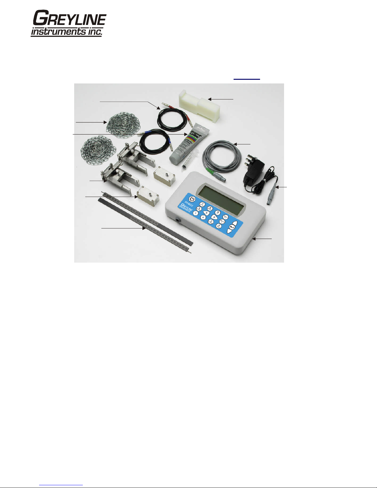
1.3 Supplied Hardware...........................................................................................................8
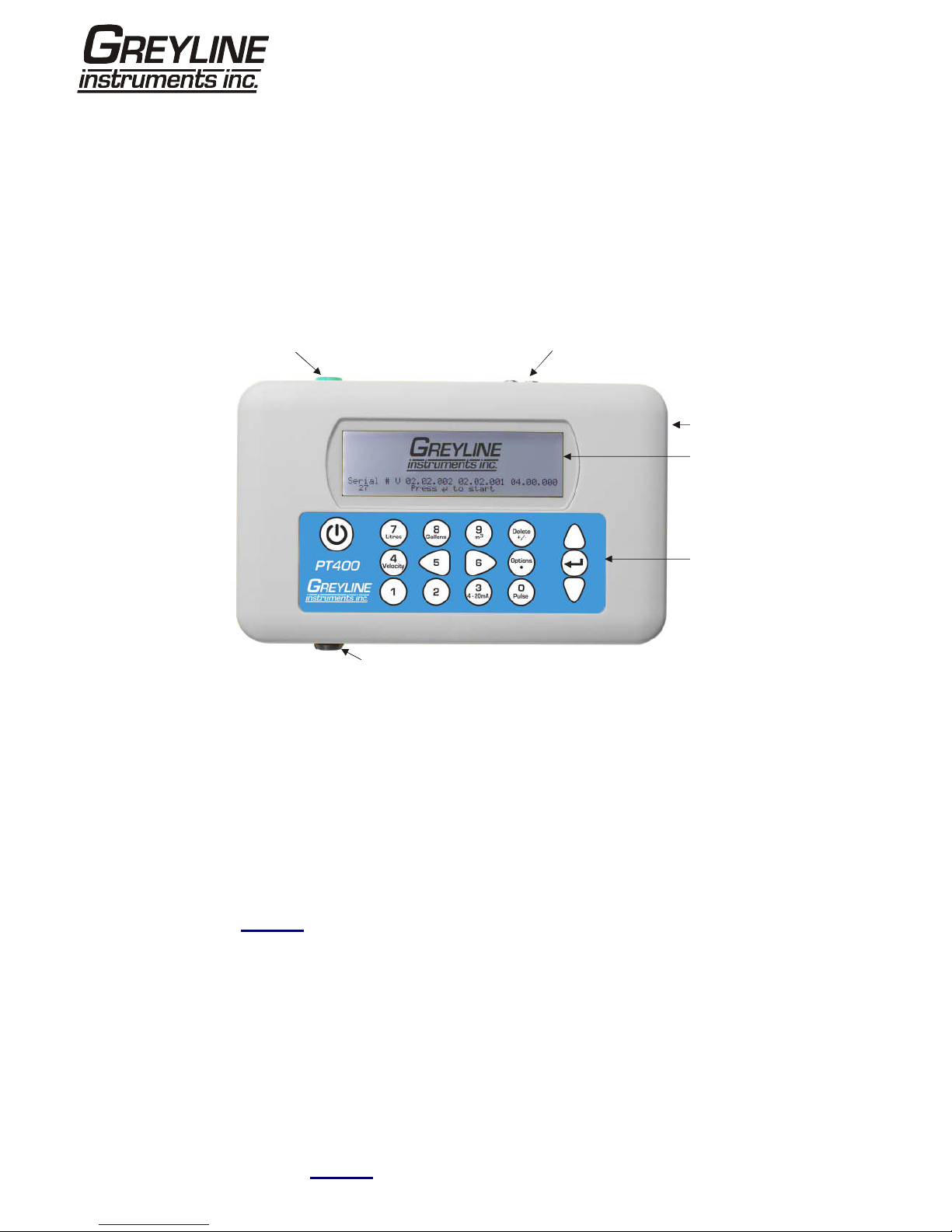
1.4 Portaflow PT400 Instrument.............................................................................................9
1.4.1 Connectors.............................................................................................................9
1.4.2 Keypad ..................................................................................................................10
1.4.3 Power supply and battery charging.......................................................................11
1.5 Transducers.....................................................................................................................11
2: Installation……………………………………………………………………………………………..12
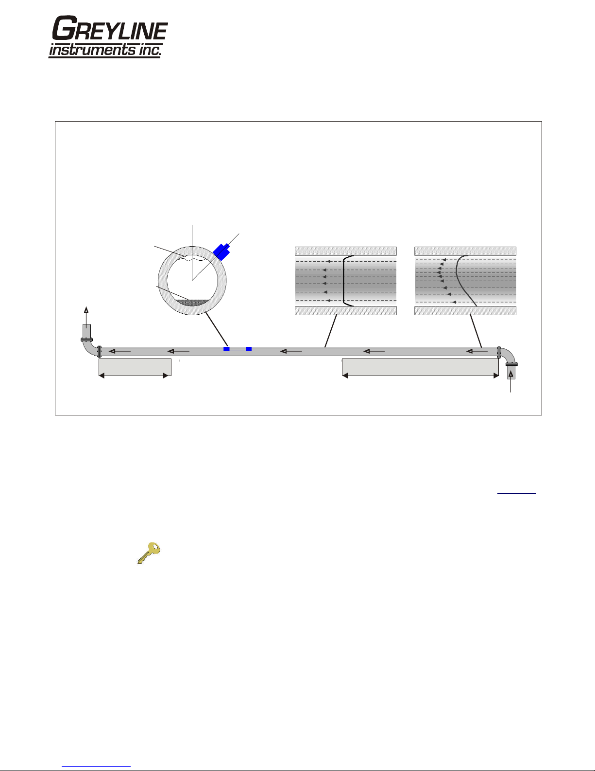
2.1 Transducer Positioning....................................................................................................12
2.2 Transducer Attachment (Type ‘A’ & ‘B’)..........................................................................13
2.2.1 Preparation...........................................................................................................13
2.2.2 Attaching the guide rails.......................................................................................13
2.2.3 Fitting the transducers..........................................................................................14
3: Operating Procedures..............................................................................................................15
3.1 Setting-up the Instrument...............................................................................................16
3.1.1 Using the instrument for the first time ..................................................................16
3.1.2 Enabling/disabling the backlight...........................................................................17
3.2 Using the Quick Start Menu ............................................................................................17
3.3 Using the System at a Regularly Monitored Location.....................................................20
3.4 Managing Named Sites...................................................................................................22
3.4.1 Setting up a new site............................................................................................22
3.4.2 Changing a site name ..........................................................................................23
3.5 Instrument Calibration .....................................................................................................24
3.5.1 Adjusting the zero cut-off .....................................................................................24
3.5.2 Adjusting the set zero flow offset .........................................................................24
3.5.3 Adjusting the calibration factor.............................................................................25
3.5.4 Adjusting the roughness factor.............................................................................25
3.5.5 Adjusting the damping factor................................................................................27
3.6 Performing Monitoring Functions ....................................................................................28
3.6.1 How to measure totalised flows (manually) .........................................................28
3.7 Configuring the Portaflow PT400 Interfaces ...................................................................30
3.7.3 How to turn the 4-20mA output OFF/ON .............................................................30
3.7.4 4-20mA signal calibration and ranging.................................................................30

Page 3 www.greyline.com
3.7.5 How to convert the measured current to flow rate...............................................31
3.7.6 How to turn the pulse output OFF/ON..................................................................32
3.7.7 Pulse output signal calibration .............................................................................32
4: Maintenance & Repair..............................................................................................................33
5: Troubleshooting.......................................................................................................................34
5.1 Overview..........................................................................................................................34
5.2 General Troubleshooting Procedure...............................................................................35
5.3 Warning & Status Messages...........................................................................................36
5.4 Test Block........................................................................................................................39
5.5 Microprocessor Reset Facility.........................................................................................39
5.6 Diagnostics Display.........................................................................................................40
5.7 Applications Hotline.........................................................................................................41
5.8 Product Return Procedure...............................................................................................41
5.9 Warranty..........................................................................................................................43
6: Appendix A Specifications......................................................................................................44

Page 4 www.greyline.com
1: General Description
1.1 Introduction
This manual describes the operation of the Greyline Portaflow PT400 portable flowmeter. The flowmeter is
designed to work with clamp-on transducers to enable the flow of a liquid within a closed pipe to be measured
accurately without needing to insert any mechanical parts through the pipe wall or protrude into the flow system.
Using ultrasonic transit time techniques, the Portaflow PT400 is controlled by a micro-processor system which
contains a wide range of data that enables it to be used with pipes with an outside diameter ranging from 13mm
up to 1000mm and constructed of almost any material. The instrument will also operate over a wide range of fluid
temperatures.
The PT400 series comprises two models which are identical in operation but designed to be used with a different
range of pipe diameters. The PT400 can be used with pipes in the range 13mm – 115mm and the PT500 with
pipes in the range 50mm – 1000mm.
Easy to operate, the Portaflow PT400 standard features are:
•Large, easy to read graphic display with backlighting
•Simple to follow dual function keypad
•Simple ‘Quick Start’ set up procedure
•Continuous signal monitoring
•Pulse output
•4-20mA, 0-20mA or 0-16mA output
•Rechargeable battery
•Battery management
•Diagnostics
Volumetric flow rates are displayed in l/h, l/min, l/sec, gal/min, gal/h, USgals/min, USgals/h, Barrel/h, Barrel/day,
m³/s, m³/min, m³/h. Linear velocity is displayed in metres or feet per second.
When operating in the ‘Flow Reading’ mode the total volumes, both positive and negative, are displayed up to a
maximum 12-digit number.
The flowmeter can be used to measure clean liquids or oils that have less than 3% by volume of particulate
content. Cloudy liquids such as river water and effluent can be measured along with cleaner liquids such as
demineralised water.
Typical Portaflow PT400 applications include:
•River water
•Seawater
•Potable water
•Demineralised water
•Treated water

Page 5 www.greyline.com
Fluid flow
Fluid flow
Fluid flow
Fluid flow
Fluid flow
U
U
U
U
D
D
D
D
Separation
Distance
Separation
Distance
Separation
Distance
Separation
Distance
Reflex mode
Reflex mode (double bounce)
Reflex mode (triple bounce)
Diagonal mode
This is the mode most commonly used.
The two transducers (U & D) are attached
to the pipe in line with each other and the
signals passing between them are reflected
by the opposite pipe wall.
The separation distance is calculated by
the instrument in response to entered data
concerning the pipe and fluid characteristics.
In this mode the separation distance is
calculated to give a double bounce. This is
most likely to occur if the pipe diameter is
so small that the calculated reflex mode
separation distance would be impractical
for the transducers in use.
This illustration goes one step further to show
a triple bounce situation. This would normally
apply when working with very small pipes
relative to the transducer range in use.
This mode might be selected by the
instrument where relatively large pipes are
concerned. In this mode the transducers are
located on opposite sides of the pipe but the
separation distance is still critical in order
for the signals to be received correctly.
This mode might be used with the standard
‘A’ & ‘B’ transducer sets but for really large
pipe installation the optional transducer set ‘D’
might be recommended.
Upstream
transducer
1.2 Principles of Operation
When ultrasound is transmitted through a liquid the speed at which the sound travels through the liquid is
accelerated slightly if it is transmitted in the same direction as the liquid flow and decelerated slightly if transmitted
against it. The difference in time taken by the sound to travel the same distance but in opposite directions is
therefore directly proportional to the flow velocity of the liquid.
The Portaflow PT400 system employs two ultrasonic transducers attached to the pipe carrying the liquid and
compares the time taken to transmit an ultrasound signal in each direction. If the sound characteristics of the fluid
are known, the Portaflow microprocessor can use the results of the transit time calculations to compute the fluid
flow velocity. Once the flow velocity is known the volumetric flow can be easily calculated for a given pipe
diameter.
The Portaflow system can be set up to operate in one of four modes determined mainly by the pipe diameter and
the type of transducer set in use. The diagram below illustrates the importance of applying the correct separation
distance between the transducers to obtain the strongest signal.
Figure 1.1 Operating modes

Page 6 www.greyline.com
1.3 Supplied Hardware
The Portaflow equipment is supplied in a rugged plastic carrying case fitted with a foam insert to give added
protection for transportation. The supplied components are shown in Figure 1.2.
Figure 1.2 Standard Portaflow equipment
Standard equipment
•Portaflow PT400 instrument with backlit graphic display
•Power supply - with UK, US, European adaptors. 110/240VAC
•4-20mA/Pulse Output cable
•2 lengths of chain each at 3.3 metres long
•Test block
•Transducer cables (x2) 2 metres long (one red and one blue)
•Transducer set 'A' (Transducers x2)
or
•Transducer set 'B' (Transducers x2)
•Set of guide rails for use with ‘A’ or ‘B’ transducers
•Ruled separation bar (2-piece)
•Manual
Transducer Cables Test Block
4-20mA/
Pulse Output
Cable
Power Supply
(Batt. Charger)
Portaflow PT400
Instrument
Chains (x2)
Guide Rails (x2)
Ruled Separation bar
Transducers
(Sensors x2)
Ultrasonic
Couplant

Page 7 www.greyline.com
1.4 Portaflow PT400 Instrument
The Portaflow PT400 is a microprocessor controlled instrument operated through a menu system using an inbuilt
LCD display and keypad. It can be used to display the instantaneous fluid flow rate or velocity, together with
totalised values.
The instrument can also provide a current or variable ‘pulse’ output proportional to the detected flow rate. These
outputs, which can be used with a range of external interface devices such as those found in BMS or site
monitoring systems, can be calibrated to suit a particular flow range.
1.4.1 Connectors
Figure 1.3 Instrument details
Transducer connections
The transducers are connected to two colour-coded miniature coaxial sockets located on the top of the
instrument. Using the red/blue connector cables provided, the upstream transducer should always be connected
to the RED socket and the downstream transducer to the BLUE one for a positive flow reading. It is safe to
connect or disconnect the cable while the instrument is switched on.
4-20mA and Pulse output connection
The 4-20mA / ‘pulse’ output cable should be connected to the green 7-pin connector on the top of the flowmeter,
as shown in Figure 1.3. A single cable that can be adapted for use for either of these output functions is included
in the Portaflow PT400 kit. The ‘tails’ on the free end of the cable must be terminated to suit the intended
application.
Red – 4-20mA positive
Black – 4-20mA negative
White – Pulse output
Green – Pulse return
Brown – Set Point (not in present use)
Blue – Set Point return (not in present use)
Thick Black – Cable screen
Battery charger connection
The supplied battery charger is connected to the instrument by means of the grey 2-pin connector on the bottom
of the unit, as shown in Figure 1.3.
4-20mA / Pulse Output Transducer Cables
Reset pin-hole
LCD Display
Keypad
Battery Charger

Page 8 www.greyline.com
Note: The above connectors have different key-ways to prevent incorrect cable connection.
Figure 1.4 Keypad
1.4.2 Keypad
The instrument is configured and controlled via a 16-key tactile membrane keypad, as shown in Figure 1.4.
ON/OFF Key
The ON/OFF key is shown on the top left of the keypad. When turned ON an initialisation screen is displayed on
the LCD showing the instrument’s serial number and software revision. Once this appears, the instrument can be
started by pressing the ENTER key once – the initialization screen is then replaced by a MAIN MENU which
provides access to the remaining functions.
Menus and the menu selection keys
The Portaflow PT400 menus are arranged hierarchally with the MAIN MENU being at the top level. Menu
navigation is achieved by three keys on the right hand side of the keypad which are used to scroll UP and DOWN
a menu list and SELECT a menu item. When scrolling through a menu an arrow-shaped cursor moves up and
down the left hand side of the screen to indicate the active menu choice which can then be selected by pressing
the ENTER (SELECT) key.
Some menus have more options than can be shown on the screen at the same time, in which case the
‘overflowed’ choices can be brought into view by continuing to scroll DOWN past the bottom visible item. Menus
generally ‘loop around’ if you scroll beyond the first or last items.
If you select Exit it usually results in taking you back one level in the menu hierarchy, but in some cases it may go
directly to the ‘Flow Reading’ screen.
Some screens require you to move the cursor left and right along the display as well as up and down. This is
achieved using keys 5 (scroll LEFT) and 6 (scroll RIGHT).
Dual function numerical keypad
The block of keys shown in the centre of the keypad in Figure 1.4 are dual function keys. They can be used to
enter straight-forward numerical data, select the displayed flow units or provide quick access to frequently
required control menus.
Note: Some of the features accessed by these keys are restricted in the Portaflow 220 model range. An “Option
not available” message is displayed if you select a restricted function.
1.4.3 Power supply and battery charging
Operating power is provided by an internal battery that can be charged from the utility supply using the supplied
external charger. When you first receive the unit you must put the battery on charge for a minimum of 6.5hrs
ON/OFF
Scroll LEFT Scroll RIGHT
Scroll UP
ENTER
(SELECT)
Numerical keypad
with dual function keys
Scroll DOWN

Page 9 www.greyline.com
before use. A fully charged battery will power the instrument for up to 20hrs depending on the output utilisation
and backlight usage.
If the backlight has been enabled the display is illuminated for 10 seconds every time a key is pressed. If the
backlight is active continuously it would reduce the available battery operating time to 8hrs. Similarly, if the 4-
20mA output is used constantly at 20mA, the battery life would reduce by 50%. It is therefore beneficial to turn off
the backlight and 4-20mA output facilities when they are not required.
When the instrument is operating in the ‘Flow Reading’ mode the percentage battery charge level is displayed
symbolically on the LCD screen. A warning message is triggered if the charge falls to approximately 30%, at
which point there is up to four hours of battery operation remaining, depending on usage. The battery can be
charged both while the instrument is in use or when switched off. The instrument’s internal data is stored in non-
volatile memory and will not be lost even if the battery discharges completely.
Key Point: The battery is not a user-changeable item. The instrument must be
returned to Greyline if the battery needs replacing.
Key Point: Only use the supplied charger, or special adaptor lead. Failure to comply
with this will invalidate your warranty.
1.5 Transducers
Different transducer sets are provided with the PF400A and PF400B Portaflow models and are not
interchangeable.
Key Point: Always use the transducers that were supplied with the instrument.
Transducer set 'A'
Supplied as standard on PF400A for use on pipes 0.51” to 4.525” (13mm to 115mm) outside diameter.
Transducer set 'B'
Supplied as standard on PF400B for use on pipes 1.97” to 39.37” (50mm to 1000mm) outside diameter.

Page 10 www.greyline.com
2: Installation
2.1 Transducer Positioning
Figure 2.1 Locating the transducers
To obtain the most accurate results the condition of both the liquid and the pipe wall must be suitable to allow the
ultrasound transmission along its predetermined path. It is important also that the liquid flows uniformly within the
length of pipe being monitored and that the flow profile is not distorted by any upstream or downstream
obstructions. This is best achieved by ensuring there is a straight length of pipe upstream of the transducers of at
least 20 times the pipe diameter and 10 times the pipe diameter on the downstream side, as shown in Figure 2.1.
Flow measurements can be made on shorter lengths of straight pipe, down to 10 diameters upstream and 5
diameters downstream, but when the transducers are positioned this close to any obstruction the resulting errors
can be unpredictable.
Key Point: Do not expect to obtain accurate results if the transducers are positioned
close to any obstructions that distort the uniformity of the flow profile.
Guide
rail
Air
Uniform Flow Profile Distorted Flow Profile
Flow
Flow
Possible
sludge
45°
20 x Diameter
10 x Diameter
Valid transducer location
In many applications an even flow velocity profile over
a full 360° is unattainable due, for example, to the
presence of air turbulence at the top of the flow and
possibly sludge in the bottom of the pipe. Experience
has shown that the most consistently accurate results
are achieved when the transducer guide rails are
mounted at 45° with respect to the top of the pipe.
The Portaflow equipment expects a uniform flow profile as a
distorted flow will produce unpredictable measurement
errors. Flow profile distortions can result from upstream
disturbances such as bends, tees, valves, pumps and other
similar obstructions. To ensure a uniform profile the
transducers must be mounted far enough away from any
cause of distortion such that it no longer has an effect.

Page 11 www.greyline.com
2.2 Transducer Attachment
The transducers are fitted to adjustable guide rails which are secured to the pipe using wrap-around chains and
mechanically connected together by a steel separation bar. The separation bar also acts as a ruler to allow the
distance between the transducers to be accurately set to the value determined by the Portaflow instrument.
When fitting the guide rails it is easiest to assemble them onto the separation bar and adjust to the required
separation distance before attaching them to the pipe.
2.2.1 Preparation
1. Before you attach the transducers you should first ensure that the proposed location satisfies the
distance requirements shown in Figure 2.1 otherwise the resulting accuracy of the flow readings may be
affected.
2. Prepare the pipe by degreasing it and removing any loose material or flaking paint in order to
obtain the best possible surface. A smooth contact between pipe surface and the face of the transducers is
an important factor in achieving a good ultrasound signal strength and therefore maximum accuracy.
2.2.2 Attaching the guide rails
Figure 2.2 Guide rail attachment
1. Slide the separation bar (D) into the front of the left hand guide rail, align the front edge of the
guide rail with ‘0’ on the ruler scale (E) and secure it in place by tightening the thumbscrew (C).
2. Slide the other end of the separation bar into the front of the right hand guide rail, align the front
edge of the guide rail to the required separation distance (obtained from the Portaflow instrument) on the
ruler (F), then secure it in place by tightening the thumbscrew.
A
B
C
D
E
F
G
A: Tensioning thumb-wheel.
B: Tension bar.
C: Separation bar securing
screw.
D: Separation bar.
E: Ruler scale (0).
F: Set Separation distance.
G: Securing chain.

Page 12 www.greyline.com
3 On each guide rail, attach one end of a securing chain to a hook on the tensioning bar (B), wrap the chain
around the pipe (G) and then attach it to the hook on the other end of the tensioning bar whilst keeping the
chain as tight as possible.
4. Rotate the complete guide rail assembly so that it is approximately 45° with respect to the top of
the pipe. Then tighten the chain by turning the tensioning thumb-wheel (A) on each guide block until the
assembly is securely attached to the pipe.
Note: If you are unable to get sufficient tension on the chain to hold the assembly in place, fully slacken the
tensioning thumb-wheel and shorten the effective length of the chain wrapped around the pipe by connecting
the tensioning bar to the next link in the chain, then re-tension.
2.2.3 Mounting the transducers
Figure 2.3 Mounting the transducers
1. Slide the transducer cover plate (A) fully towards the outside of the guide assembly to allow
sufficient access to fit the transducer.
2. Clean the face of the transducer, removing all traces of dirt and grease.
3. Apply a 1/8” (3mm) bead of ultrasonic couplant along the centre length of the transducer (E).
4. Fit the transducer into the guide block – ensuring the lugs on the sides of the transducer are
correctly located into the slots on the sides of the guide block (B).
5. Slide the transducer cover plate (A) over the top of the transducer and tighten the thumbscrew
(C) finger tight to secure the transducer in place. When securing the cover plate take care to leave sufficient
room around the transducer connector (D) to connect the cable.
6. Repeat the above steps for the second transducer.
7. Connect the transducers to the Portaflow instrument using the coaxial cables provided. The RED
cable must be connected to the upstream transducer and the BLUE cable to the downstream transducer. If
you observe negative flow, swap the red and blue cables at the sensors.
C: Transducer cover platesecuring screw.
B: Transducer locating slot/lug.
D: Transducer cable connection.
A: Transducer cover plate.
G: Chain.
E: Ultrasonic
couplant
application.

Page 13 www.greyline.com
QUICK START VIEW EDIT SITE DATA
Enter data
Attach sensors
FLOW READING
Choose site / check data
Attach sensors
FLOW READING
Set up a named site
At a one-off location
(Paragraph 3.2)
At a frequent location
(Paragraph 3.3)
Manage site details
(Paragraph 3.4)
Carry out any necessary calibration
(Paragraph 3.5)
How to adjust the Zero Flow Offset – Paragraph 3.5.2
How to adjust the Calibration Factor– Paragraph 3.5.3
How to adjust the Roughness Factor– Paragraph 3.5.4
How to adjust the Damping Factor – Paragraph 3.5.5
Set-up a monitoring or logging application
(Paragraph 3.6)
How to measure totalised flows – Paragraph 3.6.1
How to set up basic (manual) logging – Paragraph 3.6.2
How to set up auto-timed logging – Paragraph 3.6.3
How to set up logging ‘live’ to a PC– Paragraph 3.6.4
How to download saved data to a PC – Paragraph 3.6.5
How to print data – Paragraph 3.8
Configure the interfaces
(Paragraph 3.7)
Battery charging, Set date/time, Language, Backlight
Initial instrument setup
(Paragraph 3.1)
Connect and take basic flow readings
Rename a site
RS232 set-up – Paragraph 3.7.1
USB set-up – Paragraph 3.7.2
4-20mA ON/OFF – Paragraph 3.7.3
4-20mA Calibration – Paragraph 3.7.4
Pulse ON/OFF – Paragraph 3.7.6
Pulse calibration – Paragraph 3.7.7
3: Operating Procedures

Page 14 www.greyline.com
3.1 Setting-up the Instrument
3.1.1 Using the instrument for the first time
Before you use your Portaflow PT400 for the first time you should first charge the battery, then select the display
language and set-up the internal clock, as described below.
Charging the battery
1. Connect the external battery charger to the charger socket at the bottom of the instrument then
switch on the utility supply.
2. The instrument should indicate CHARGING
and an animated battery symbol indicates that the
battery is taking on charge.
3. Leave the instrument on charge for 6.5 hours
before using it for the first time.
CHARGING DD-MM-YY HH:MM:SS
Selecting a language
The first time you switch on the instrument you may be asked to select a user language.
1. Switch on the instrument by pressing the ON/OFF button.
2. If necessary, select the required language using the UP/DOWN scroll keys then press the
ENTER key.
3. The selected language will be the default
when the instrument is next used. To change the
language again select the Change Language
option in the SETUP INSTRUMENT screen (see
below)
4. The initialisation screen will be displayed,
giving details of the instrument’s serial number
and software revision details.
5. Press ENTER to start the instrument.
6. This is the MAIN MENU and is the starting
point for all the operations described in this
chapter.
Serial # V 00.00.00.00.00.00.00. 0000
27 Pressto start
MAIN MENU DD-MM-YY HH:MM:SS
Quick start
View/Edit Site Data
Data Logger
Setup RS232 /USB
Setup Instrument
Read flow

Page 15 www.greyline.com
Setting the Date & Time
1. Select Setup Instrument from the MAIN MENU.
The screen shown here should be displayed.
2. Select Set Date & Time and click ENTER.
3. A flashing cursor should appear under the first
date number. Enter the date sequence in dd-mm-
yy order then press ENTER.
4. Repeat this action to set the time.
5. Select Exit then press ENTER to return to the
MAIN MENU.
SETUP INSTRUMENT DD-MM-YY HH:MM:SS
Dim: mm
Set Date & Time : dd-mm-yy hh:mm:ss
Calibrate 4-20mA
Pulse output
Backlight : Disabled
Factory settings
Change Language
Exit
Note: If you make a mistake when entering the data press the Delete key to move the cursor back to the number
you wish to change, then continue. If you enter an invalid number an ‘ERR:Invalid Date or Time!’ error message is
displayed on the second line of the screen. If this occurs repeat the set date/time procedure.
3.1.2 Enabling/disabling the backlight
When the backlight is enabled it will illuminate for 15 seconds every time a key is pressed so if it is not required it
is recommended that you disable it to prolong the battery discharge time.
1. Select Setup Instrument from the MAIN MENU.
2. Select Backlight from the SETUP
INSTRUMENT screen then press ENTER.
SETUP INSTRUMENTDD-MM-YY HH:MM:SS
Dim: mm
Set Date & Time : dd-mm-yy hh:mm:ss
Calibrate 4-20mA
Pulse output
Backlight : Disabled
Factory settings
Change Language
Exit
3. Select Enable or Disable as required.
4. Press ENTER to return to the SETUP
INSTRUMENT screen.
5. Select Exit then press ENTER to return to the
MAIN MENU.
BACKLIGHT DD-MM-YY HH:MM:SS
Dim: mm
Enabled
Disabled
3.2 Using the Quick Start Menu
If you want to perform a ‘one-off’ flow reading at a particular pipe location the Quick Start menu provides the
quickest way to set up the Portaflow system and access the FLOW READING screen.
If the point at which you intend to take the measurement is likely to require regular monitoring it is best to set it up
as a ‘Site’ within the Portaflow PT400, which then stores the site parameters (See Managing Named Sites).

Page 16 www.greyline.com
Before you can use the Portaflow system you need to obtain the following details (this information will be required
when setting up the Quick Start menu):
•The pipe outside diameter
•The pipe wall thickness and material
•The pipe lining thickness and material
•The type of fluid
•The fluid temperature
Entering the site data
1. Select Quick Start from the MAIN MENU and press ENTER. You will then be presented with a
series of screens in which to enter the data mentioned above.
2. Select the dimension units (millimetres or
inches) used to measure the pipe, then press
ENTER.
DIMENSION UNITDD-MM-YY HH:MM:SS
Select the dimension units:
mm
Inches
3. Enter the pipe outside diameter dimension,
then press ENTER. OUTSIDE DIAMETERDD-MM-YY HH:MM:SS
Dimension: mm
Pipe outside diameter? 58.0
4. Enter the pipe wall thickness dimension, then
press ENTER. PIPE WALL THICKNESS DD-MM-YY HH:MM:SS
Dimension: mm
Pipe outside diameter? 58.0
Pipe wall thickness? 4.0
5. If the pipe has a lining, enter the lining
thickness.
If nothing is entered the instrument automatically
assumes there is no lining.
6. Press ENTER to continue.
PIPE LINING THICKNESS DD-MM-YY HH:MM:SS
Dimension: mm
Pipe outside diameter? 58.0
Pipe wall thickness? 4.0
Pipe lining thickness? 0.0
7. Select the pipe wall material from the list
provided, then press ENTER.
If the material is not listed select Other and enter
the propagation rate of the pipe wall material in
metres/sec. Contact Greyline if this is not known.
PIPE WALL MATERIALDD-MM-YY HH:MM:SS
Select pipe wall material
Mild Steel
S' less Steel 316
S' less Steel 303
Plastic

Page 17 www.greyline.com
Cast Iron
Ductile Iron
Copper
Brass
Concrete
Glass
Other (m/s)
8. If a lining thickness value was entered earlier,
this screen is displayed to request that you enter
the lining material type. If no lining thickness was
entered this screen will be bypassed.
9. Select the lining material from the list provided
then press ENTER.
If the material is not listed select Other and enter
the propagation rate of the lining material in
metres/sec. Contact Greyline if this is not known.
PIPE LINING MATERIAL DD-MM-YY HH:MM:SS
Select pipe lining material
Steel
Rubber
Glass
Epoxy
Concrete
Other (m/s)
10. Select the fluid type from the list provided and
press ENTER.
If the liquid is not listed select Other and enter a
propagation rate in metres/second.
FLUID TYPE DD-MM-YY HH:MM:SS
Select fluid type
Water
Glycol/water 50/50
Glycol/water 30/70
Lubricating oil
Diesel
Freon
Other (m/s)
11. If you need to alter the fluid temperature from
that shown select either °C or °F with the cursor
and press the ENTER key.
12. Enter the new temperature value and press the
ENTER key.
13. The new temperature should now be indicated
in both °C and °F.
14. Select Continue.. and press ENTER.
FLUID TEMPERATURE DD-MM-YY HH:MM:SS
Enter Fluid Temperature
°C: 5.00
°F: 41.00
Continue..
15. The SENSOR SEPARATION screen now
displays a summary of the entered parameters and
informs you of the type of sensor to be used, the
mode of operation and the distance to set up
between the sensors.
In this example it recommends type A-ST (A
standard) sensors operating in the ‘Reflex’ mode
spaced at 32.2mm apart.
Take a note of these details
SENSOR SEPARATION DD-MM-YY HH:MM:SS
Site : Quickstart
Pipe : 58.00 mm
Wall : 4.00
Sensors : A-ST Reflex
Temperature : 10.00°C 50.00°F
Set sensor separation to 32.2 mm
Pressto continue, to select sens.

Page 18 www.greyline.com
Note: Do not press ENTER until the transducers are fitted and connected to the instrument.
Attaching and connecting the transducers
16. Fit the designated sensors to the pipe using the appropriate guide rails as described in
Paragraph 2.2. Take great care to set the separation distance as accurately as possible.
17. Connect the red and blue coaxial cables between the sensors and the test instrument, ensuring
that the red connector on the instrument is connected to the ‘upstream’ sensor.
Taking a flow reading
18. Once the transducers have been fitted and
connected press the Enter key.
19. This will take you from the SENSOR
SEPARATION screen to the FLOW READING
screen via a signal-checking screen (shown here).
Please wait..
Checking signals
****************************************
* *
****************************************
20. Check that the indicated signal strength on the
left of the screen is at least 2 bars (ideally 3 or 4). If
less than 2 bars are shown it indicates there could
be a problem with the transducer spacing,
alignment or connections; or it could be due to an
application problem.
FLOW READINGDD-MM-YY HH:MM:SS
Dim: mm
Signal
0.000
l/min
+Total: 0.00 litres
–Total: 0.00 litres
Flow monitoring
The FLOW READING screen is the one most used during normal monitoring operation. It shows the
instantaneous fluid flow together with totalised values (when enabled). In this mode you can select the flow rate
measurement units by pressing keys 7 (litres), 8 (Gallons) or 9 (m³), or change the display to show velocity by
pressing key 4.
3.3 Using the System at a Regularly Monitored Location
Setting up the Portaflow system using the Quick Start method described in Paragraph 3.2 is easy and the
recommended method to use in a ‘one-off’ situation. But if you have a site location that you want to monitor on a
frequent basis it is better to set up a named ‘Site’ for that location so that you can recall it when needed and so
avoid the need to re-enter the site details every time you want to install the equipment there.
Note: See Paragraph 3.4 for details of how to set-up and manage site details.
Use this procedure to install the equipment at a named site.
1. Select View Edit Site Data from the MAIN
MENU.
2. Select Choose from list of sites.
3. Select one of the sites listed and press ENTER.
4. The Site name will show the selected site and
VIEW EDIT SITE DATADD-MM-YY HH:MM:SS
Dim: mm
Choose from list of sites
Site name : MySite
Dimension units : mm
Pipe outside diameter : 58.00
Pipe wall thickness : 4.00
Pipe lining thickness : 0.00

Page 19 www.greyline.com
the site parameters will be listed on the screen.
5. Scroll down through the menu list and
enter/change the data that might have changed
since the last time the site was accessed.
6. When you are satisfied that the parameters are
correct select Save current site & read flow.
Pipe wall material : Mild Steel
Lining material : ---------
Sensor set : A-ST
Sensor mode : Reflex
Fluid type : Water
Save current site & read flow
Delete this Site
Download & save current site
Exit
7. If you need to alter the fluid temperature from
that shown select either °C or °F with the cursor
and press the ENTER key.
8. Enter the new temperature value and press the
ENTER key.
9. The new temperature should now be indicated
in both °C and °F.
10. Select Continue.. and press ENTER.
FLUID TEMPERATURE DD-MM-YY HH:MM:SS
Enter Fluid Temperature
°C: 5.00
°F: 41.00
Continue..
11. The SENSOR SEPARATION screen now
displays a summary of the entered parameters and
informs you of the type of sensor to be used, the
mode of operation and the distance to set up
between the sensors.
In this example it recommends type A-ST (A
standard) sensors operating in the ‘Reflex’ mode
spaced 32.2mm apart.
Take a note of these details.
SENSOR SEPARATION DD-MM-YY HH:MM:SS
Site : MySite
Pipe : 58.00 mm
Wall : 4.00
Sensors : A-ST Reflex
Temperature : 10.00°C 50.00°F
Set sensor separation to 32.2 mm
Pressto continue, to select sens.
Note: If you press ENTER before the transducers are fitted and connected to the instrument, the instrument
will detect a low signal strength and may indicate an ERROR condition.
Attaching and connecting the transducers
12. Fit the designated sensors to the pipe using the appropriate guide rails as described in
Paragraph 2.2. Take great care to set the separation distance as accurately as possible.
13. Connect the red and blue coaxial cables between the sensors and the instrument, ensuring that
the red connector on the instrument is connected to the ‘upstream’ sensor.
Taking a flow reading
14. Once the transducers have been fitted and
connected press the ENTER key.
15. This will take you from the SENSOR
SEPARATION screen to the FLOW READING
screen via a signal-checking screen (shown here).
Please wait..
Checking signals
****************************************
* *
****************************************

Page 20 www.greyline.com
16. Check that the indicated signal strength on the
left of the screen is at least 2 bars (ideally 3 or 4). If
less than 2 bars are shown it indicates there could
be a problem with the transducer spacing,
alignment or connections; or it could be due to an
application problem.
FLOW READING DD-MM-YY HH:MM:S
Signal Dim: mm
0.000
l/min
+Total: 0.00 litres
–Total: 0.00 litres
Flow monitoring
The FLOW READING screen is the one most used during normal monitoring operation. It shows the
instantaneous fluid flow together with totalised values (when enabled). In this mode you can select the flow rate
measurement units by pressing keys 7 (litres), 8 (Gallons) or 9 (m³), or change the display to show velocity by
pressing key 4.
3.4 Managing Named Sites
If you want to monitor a particular site location frequently you can set up a named ‘Site’ to store the installation
details, such as pipe dimensions and material, required to set-up the Portaflow PT400 system. These can then be
recalled later when revisiting that particular location.
The instrument can store up to 20 sites, the first site is reserved for QUICK START and cannot be renamed;
subsequent sites are initially named EmptySite1 through to EmptySite19.
3.4.1 Setting up a new site
1. Select View Edit Site Data from the MAIN
MENU.
2. Select Choose from list of sites.
3. Select one of the EmptySites from the
presented list (e.g. EmptySite 1 as shown).
4. Select Site name and press ENTER.
VIEW EDIT SITE DATA DD-MM-YY HH:MM:SS
Dim: mm
Choose from list of sites
Site name : EmptySite1
Dimension units : mm
Pipe outside diameter : 58.00
Pipe wall thickness : 4.00
Pipe lining thickness : 0.00
5. This opens the ALTER NAME screen.
6. Select Alter the Site Name and you will be
presented with a screen which allows you to enter
a new name in much the same way as when
composing a mobile text message.
7. On completion press ENTER then select Exit.
This will take you back to the VIEW EDIT SITE
DATA screen.
ALTER NAME DD-MM-YY HH:MM:SS
Site name : EmptySite1
Do you wish to:–
Alter the Site Name
Exit
Table of contents
Other Greyline Measuring Instrument manuals
Popular Measuring Instrument manuals by other brands

Fluke
Fluke RUSKA 2465A-754 user manual

Vitalograph
Vitalograph alpha 6000 Instructions for use

Detcon
Detcon 1000 Operator's installation and instruction manual

Burkert
Burkert MassFlowMeter 8700 operating instructions

Brüel & Kjaer Vibro
Brüel & Kjaer Vibro VIBROCONTROL 950 Short Instruction

Agilent Technologies
Agilent Technologies B1500A Self-paced training manual