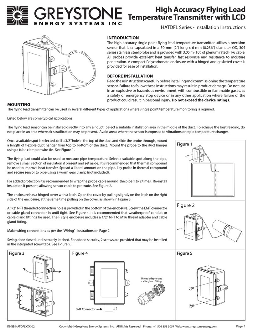
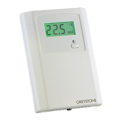
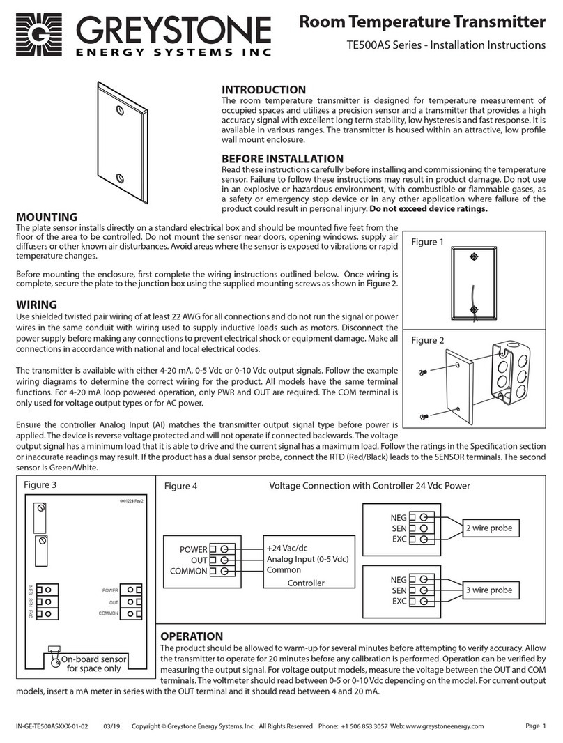
Greystone Energy Systems TE500AD Series User manual
Other Greystone Energy Systems Transmitter manuals

Greystone Energy Systems
Greystone Energy Systems CDD3B1 Series User manual
Greystone Energy Systems
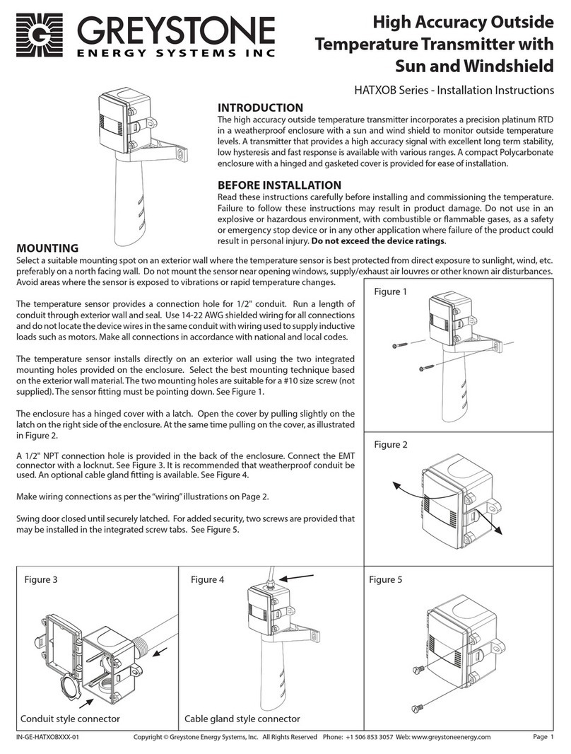
Greystone Energy Systems HATXOB Series User manual
Greystone Energy Systems
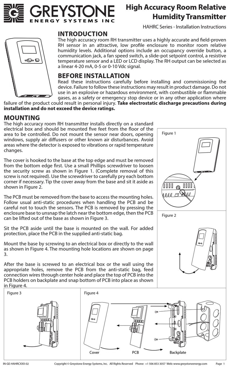
Greystone Energy Systems HAHRC Series User manual
Greystone Energy Systems
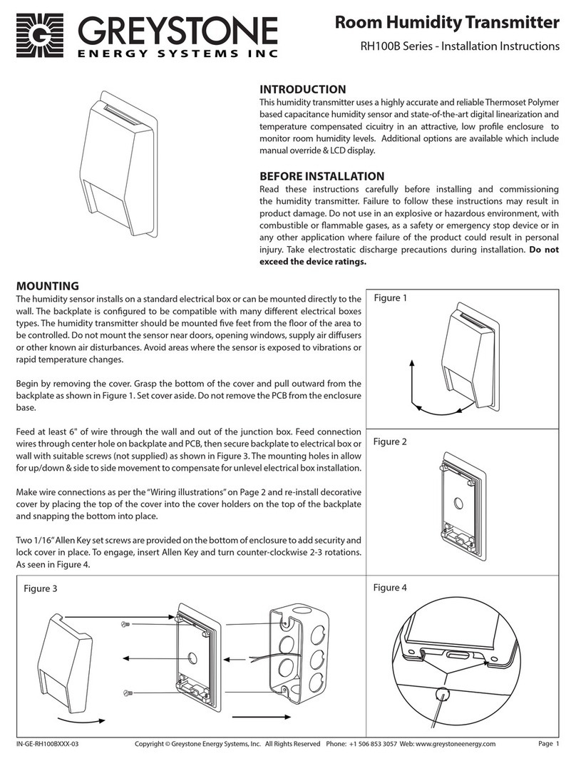
Greystone Energy Systems RH100B Series User manual
Greystone Energy Systems
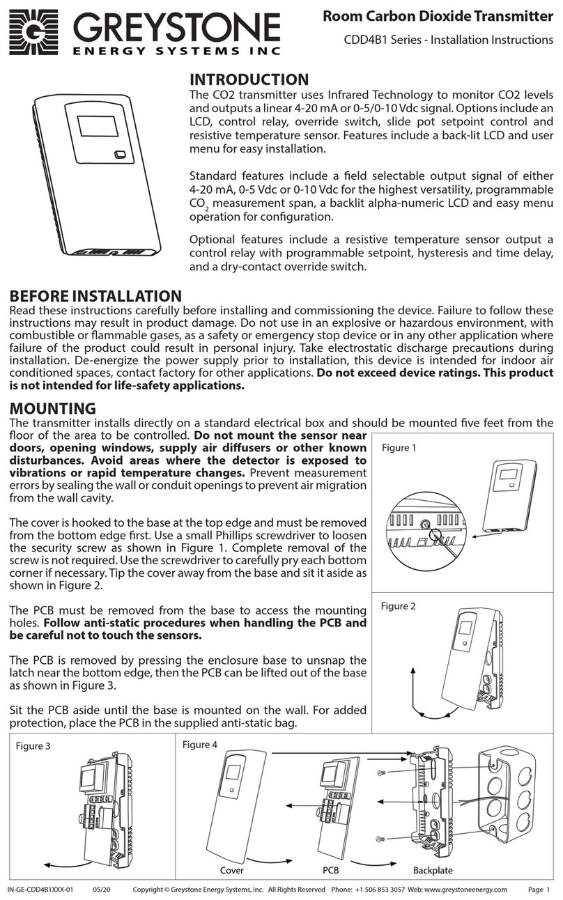
Greystone Energy Systems CDD4B1 Series User manual

Greystone Energy Systems
Greystone Energy Systems PS-2ADP Series Manual
Greystone Energy Systems
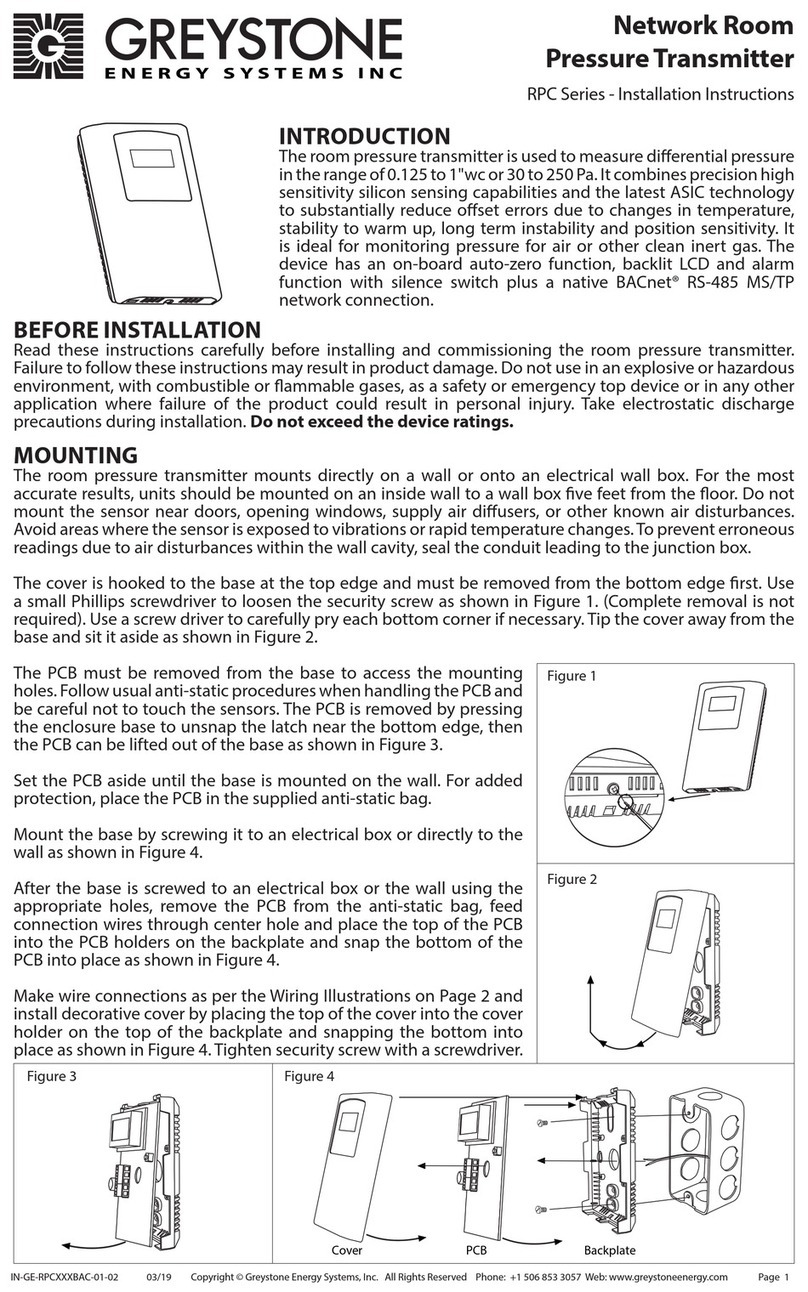
Greystone Energy Systems RPC Series User manual

Greystone Energy Systems
Greystone Energy Systems ULP1 User manual
Greystone Energy Systems
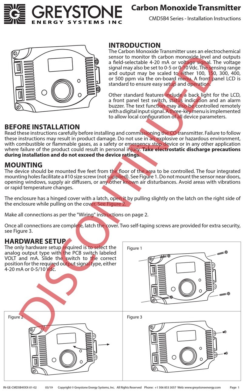
Greystone Energy Systems CMD5B4 Series User manual
Greystone Energy Systems
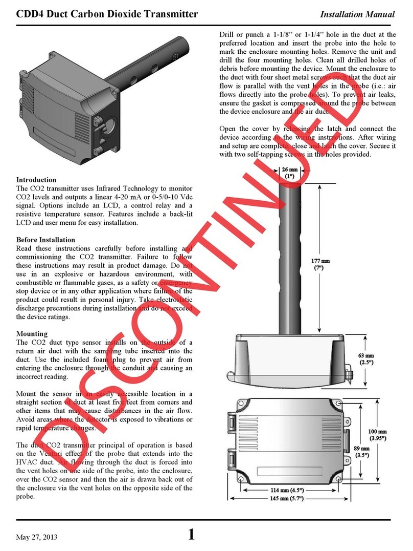
Greystone Energy Systems CDD4 User manual
Greystone Energy Systems
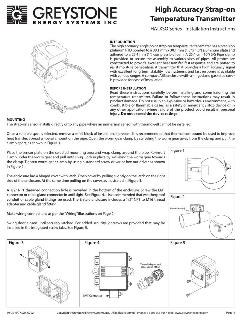
Greystone Energy Systems HATXSO Series User manual
Greystone Energy Systems
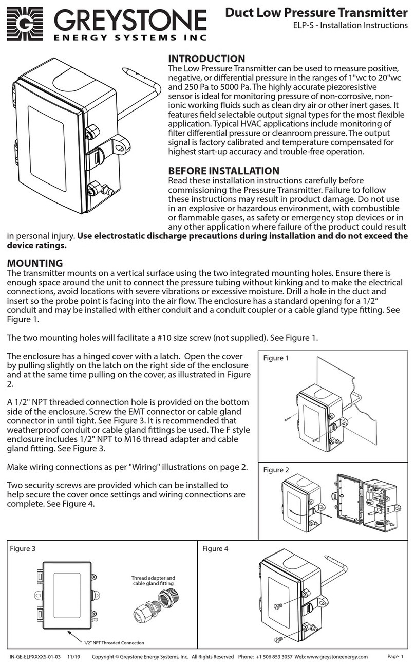
Greystone Energy Systems ELP-S User manual

Greystone Energy Systems
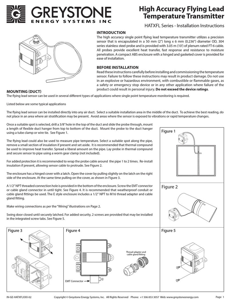
Greystone Energy Systems GDT Series User manual
Greystone Energy Systems
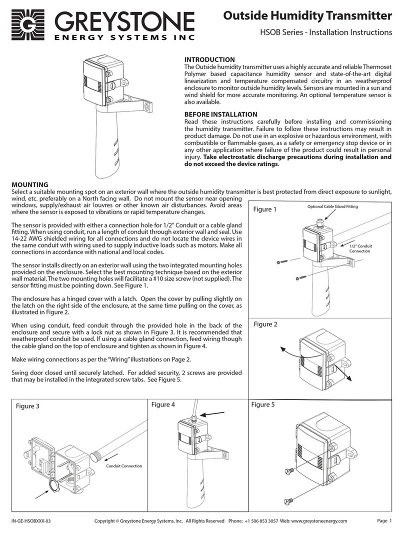
Greystone Energy Systems HATXFL Series User manual
Greystone Energy Systems
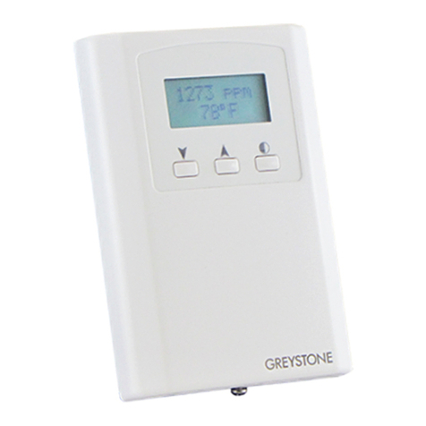
Greystone Energy Systems HSOB Series User manual
Greystone Energy Systems
Greystone Energy Systems CDD4A1 Series User manual

Greystone Energy Systems
Greystone Energy Systems CD2DT Series User manual

Greystone Energy Systems
Greystone Energy Systems CMD5B1 010 Series User manual
Greystone Energy Systems
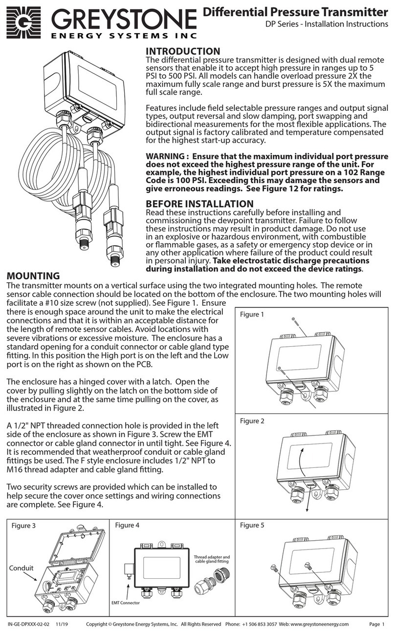
Greystone Energy Systems DP Series User manual
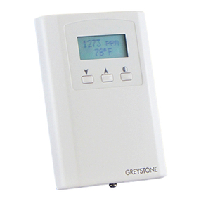
Greystone Energy Systems
Greystone Energy Systems CD2RMC Series User manual
Popular Transmitter manuals by other brands

Dejero
Dejero EnGo 3x manual

Rosemount
Rosemount 4600 Reference manual

Speaka Professional
Speaka Professional 2342740 operating instructions

trubomat
trubomat GAB 1000 instruction manual

Teledyne Analytical Instruments
Teledyne Analytical Instruments LXT-380 instructions

Rondish
Rondish UT-11 quick start guide
