PRODUCT DESCRIPTIONPRODUCT DESCRIPTION
PRODUCT DESCRIPTIONPRODUCT DESCRIPTION
PRODUCT DESCRIPTION
FOR THE POOL ALARMFOR THE POOL ALARM
FOR THE POOL ALARMFOR THE POOL ALARM
FOR THE POOL ALARM
Model DPA-10, DPA-10-D
APPLICAAPPLICA
APPLICAAPPLICA
APPLICATIONTION
TIONTION
TION::
::
:
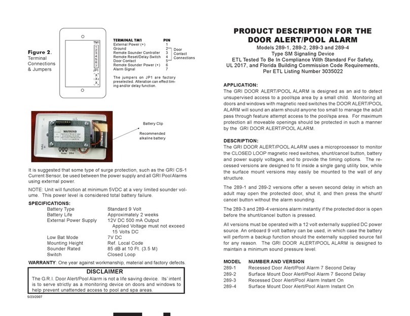
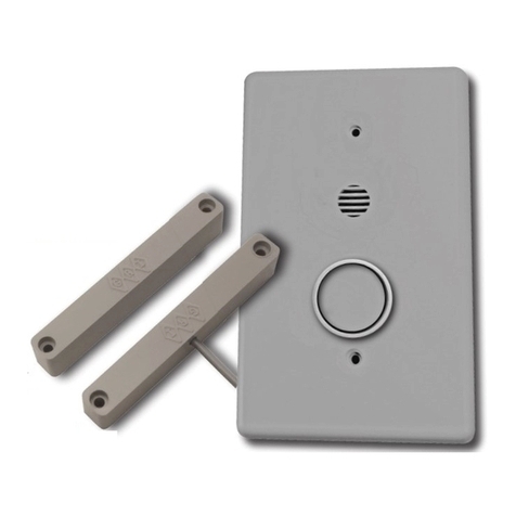
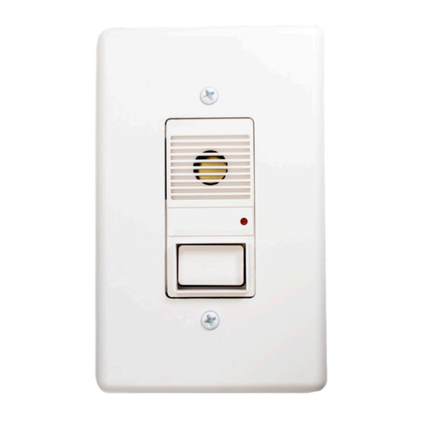
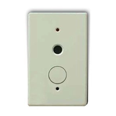
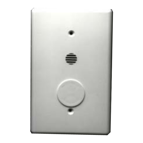
The GRI POOLALARM is designed as an aid to detect unsupervised
access to a pool/spa area by a small child. Monitoring a door or
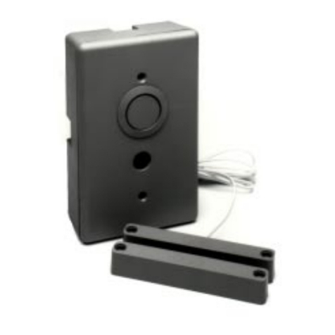
window with a magnetic reed switch(es), the POOLALARM will sound
an alarm should anyone too small to manage the adult pass through
feature attempt entrance to the pool/spa area. For maximum protec-
tion all moveable openings should be protected in such a manner by
the GRI POOLALARM. The self contained surface mounted alarm
may easily be mounted to the wall of any structure.
DESCRIPTION:DESCRIPTION:
DESCRIPTION:DESCRIPTION:
DESCRIPTION:
TheGRIPOOLALARM uses a microprocessor to monitor the CLOSED
LOOP magnetic reed switch(es), shunt/cancel button, and battery
voltage, and to provide the timing options. The POOLALARM is set
to alarm instantly if the protected door is opened before pressing the
shunt/cancel button. Model DPA-10D is set to an initial seven sec-
ond delay. In which case, alarm will wait 7 seconds upon door open-
ing before alarming. In all cases, depressing the shunt/cancel button
will provide a maximum 15 second window of alarm deactivation and
automatically reset upon expiration.
The GRI POOLALARM operates on a 9 volt battery. It is required that
a Duracell alkaline battery Model MN1604 be used.
INSTALLATION
WIRING
SPECIFICASPECIFICA
SPECIFICASPECIFICA
SPECIFICATIONSTIONS
TIONSTIONS
TIONS::
::
:
Battery Type 9VoltAlkaline Duracell
Model MN1604
Typical Battery Life Approximately 3 to 6 months
Low Battery Mode 8.5 V DC
Mounting Height Ref. Local Code
Sounder volume 85 dB at 10 Ft. (3.5 M)
Switch Closed Loop
WARNING: NOT A LIFE SAVING DEVICE.WARNING: NOT A LIFE SAVING DEVICE.
WARNING: NOT A LIFE SAVING DEVICE.WARNING: NOT A LIFE SAVING DEVICE.
WARNING: NOT A LIFE SAVING DEVICE. It is to be
used in conjunction with current safety equipment and pro-
cedures to prevent unwanted intrusions into unsupervised
areas.
TESTING:
To insure proper operation, thisAlarm Device should be tested
at least once a week by opening the door and allowingAlarm
to sound and depressing Alarm shunt/cancel button.
Door
Sw.
Batt
+ -
Figure 3
Shunt/Cancel
Sounder
LED
Door
Sw.
N/O
SCREEN DOOR
Figure 1.Wiring Diagram
Shunt/Cancel
Sounder
LED
N/O
BA-135 REV D
X
X
LISTED
When the alarm is sounding, it can only be turned off by press-
ing the cancel button. If the door is still open 15 seconds
after the cancel button is pressed, the alarm will sound again
and continue until the door is closed and the button is pressed.
The LED will flash once every 10 seconds to provide a visual
indication that the unit is working correctly. It will also flash in
a rapid succession to visually indicate the unit is in the alarm
mode.


