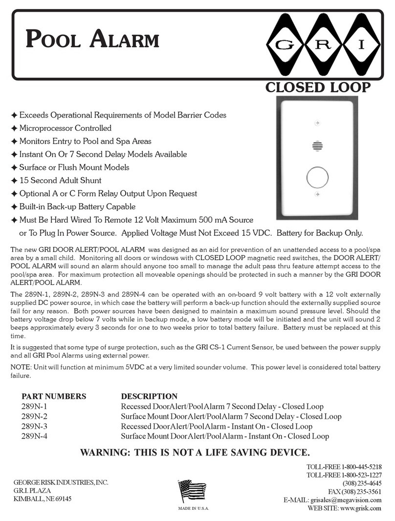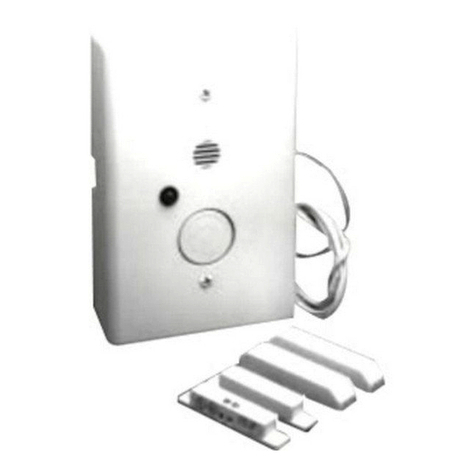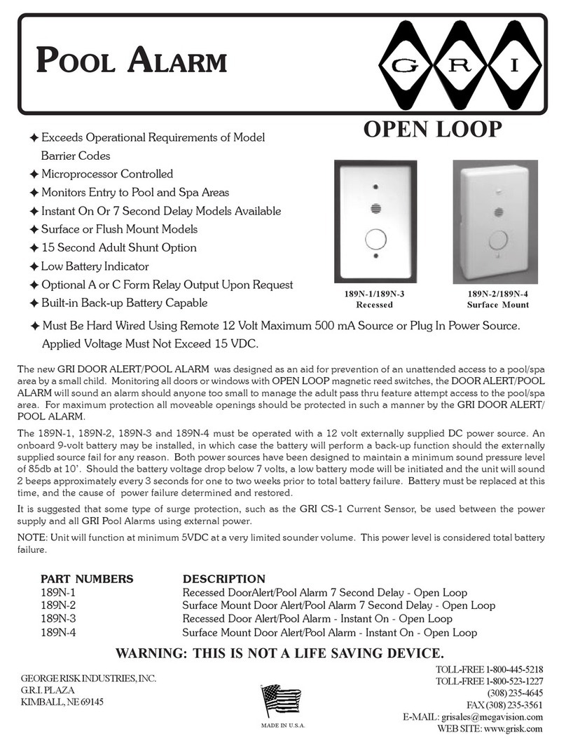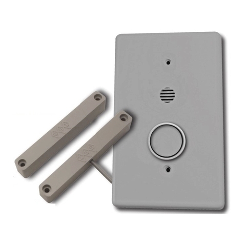
INSTALLATION INSTRUCTIONS
A) Installing the Door Sensor
NOTE: Closed Loop Switch Required.
The GRI DOORALERT/POOL ALARM uses CLOSED LOOP (nor-
mally open) magnetic reed switches. Install the magnetic reed
switch on the door according to the manufacturer’s installation
instructions. If there is a screen door, a switch should be in-
stalled on it as well. The switches should be connected in paral-
lel as in Figure 1. In this configuration the DOOR ALERT/POOL
ALARM will only activate if both doors are open. Next run the
wires from the switch(es) to where the DOOR ALERT/POOL
ALARM will be located on the wall.
B) Installing the DOOR ALERT/POOL ALARM
NOTE: The DOOR ALERT/POOL ALARM must be mounted as per local
code or regulations.
SURFACE MOUNT VERSION:
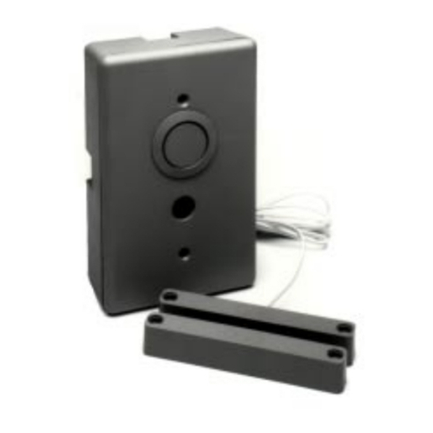
Remove the DOOR ALERT/POOL ALARM from the surface mount case.
Knockouts are provided on this case for wire access. Attach the surface
mount case directly to the wall or existing fixture, or it may be mounted to
cover a single gang electrical box. Attach the wires from door switch to
terminal TM1 pins 2 and 5. It does not matter which wire goes in which
location. Using an external 12 volt DC supply, run the wires from the
power source to the alarm unit and attach the positive voltage to pin 1 and
ground to pin 2 of terminal TM1.
If battery backup is desired, connect a standard 9 volt battery. The alarm
will beep twice during power up indicating a successful diagnostics test.
Lay the battery in the bottom of the case and reassemble the DOOR
INSTALLATION
WIRING DIAGRAM
Single Door with
Screen
ALERT/POOL ALARM with the button on the bottom and the sounder on
top. Secure with the two screws provided.
RECESSED VERSION:
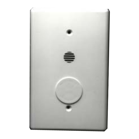
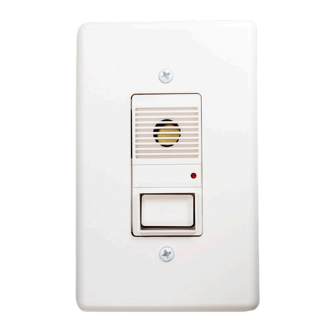
The recessed version of the DOOR ALERT/POOL ALARM is designed to
fit in a single gang utility box. Run the wires from the door sensor switch(es)
into the utility box. Attach the wires to terminal TM1 pins 2 and 5. It does
not matter which wire goes in which location. Using an external 12 volt
DC supply, run the wires from the power source to the alarm unit and
attach the positive voltage to pin 1 and ground to pin 2 of terminal TM1. If
battery back up is desired, install a standard 9 volt battery on the back of
the DOORALERT/POOL ALARM. The alarm will beep twice during power
up indicating a successful diagnostics test. Finally, insert the DOOR
ALERT/POOL ALARM into the utility box with the button on the bottom
and the sounder on top. Secure with the two screws provided.
PERTAINS TO SURFACE MOUNT AND RECESSED:
To maintain maximum sounder volume, a low battery mode will be initi-
ated. Should the voltage drop below 7 volts the low battery mode will be
triggered and the unit will sound 2 beeps approximately every 3 seconds
for one to two weeks prior to total battery failure. The battery must be
replaced at this time and the cause of power failure determined and re-
stored.
When the alarm is sounding, it can only be turned off by pressing the
shunt/cancel button. If the door is still open 15 seconds after the button
is pressed, the alarm will sound again and continue until the door is closed
and the button is pressed.
WIRING SPECIFICATION:
For connection of optional remote equipment and door contact switches a
Belden CAT5 CL2 or equivalent cable is recommended. For the connection
of the 12 volt power supply to the alarm unit a Belden 18-2 CL2-CMR 300v
60ºC or equivalent wire is recommended. In all cases installer should refer-
ence current local N.E.C. code, and/or code requirements set forth by local
housing authority or code enforcement jurisdiction.
RECOMMENDED SYSTEMS TESTING:
Periodic system testing shall be performed on a weekly basis, and should
incorporate operation of each door and window covered by the system, to
confirm an alarm sounding at each opening. Installation of on-board battery
as redundant power source shall necessitate this testing is performed with
primary power source disconnected. In all cases battery should be replaced
on a regular basis of every 80 to 90 days.
N/O
DOOR
Figure 1. Wiring Diagram
Shunt/Cancel
SCREEN
N/O
Sounder


