1.0 CONTENUTO DELL’IMBALLAGGIO
Controllate attentamente il contenuto del cartone; in caso di danni al prodotto contattate il vostro
trasportatore. Nell’imballaggio del presente proiettore sono contenuti i seguenti prodotti:
n° 1 Foglio di Istruzioni
n° 1 proiettore ACROBAT FE
n° 2 spine XLR 3 poli (1 maschio+1 femmina)
n° 1 spina di alimentazione
2.0 SICUREZZA
Prima di effettuare qualsiasi operazione sul proiettore, sconnettere fisicamente la linea di alimenta-
zione staccando la spina (ad esempio durante la sostituzione della lampada).
Questo proiettore è stato progettato per utilizzi in ambienti interni: nel caso venga utilizzato in
esterni, ACROBAT FE, deve essere posizionato al riparo dagli agenti atmosferici (ad esempio sotto
una tettoia, un porticato, ecc...). La temperatura ambiente massima non deve superare i 50°C.
Attenzione: la temperatura della superficie esterna del proiettore può raggiungere 90°C.
Attenzione: lampada molto calda, prima della sostituzione attendete almeno 10 minuti.
Si raccomanda l’utilizzo della catena di sicurezza da fissare al proiettore ed alla struttura di sospen-
sione dello stesso per evitare la caduta accidentale del proiettore nel caso, poco probabile, che il
punto di fissaggio primario dovesse cedere.
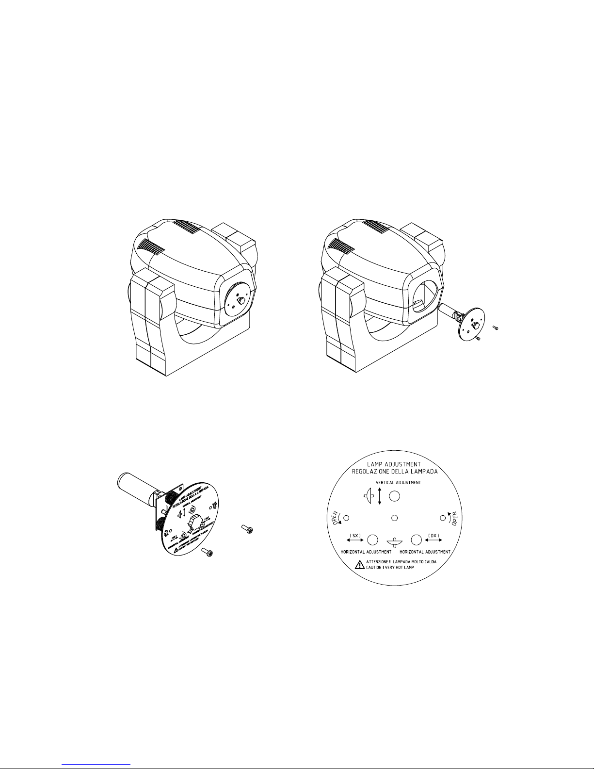
3.0 INSTALLAZIONE DEL PROIETTORE
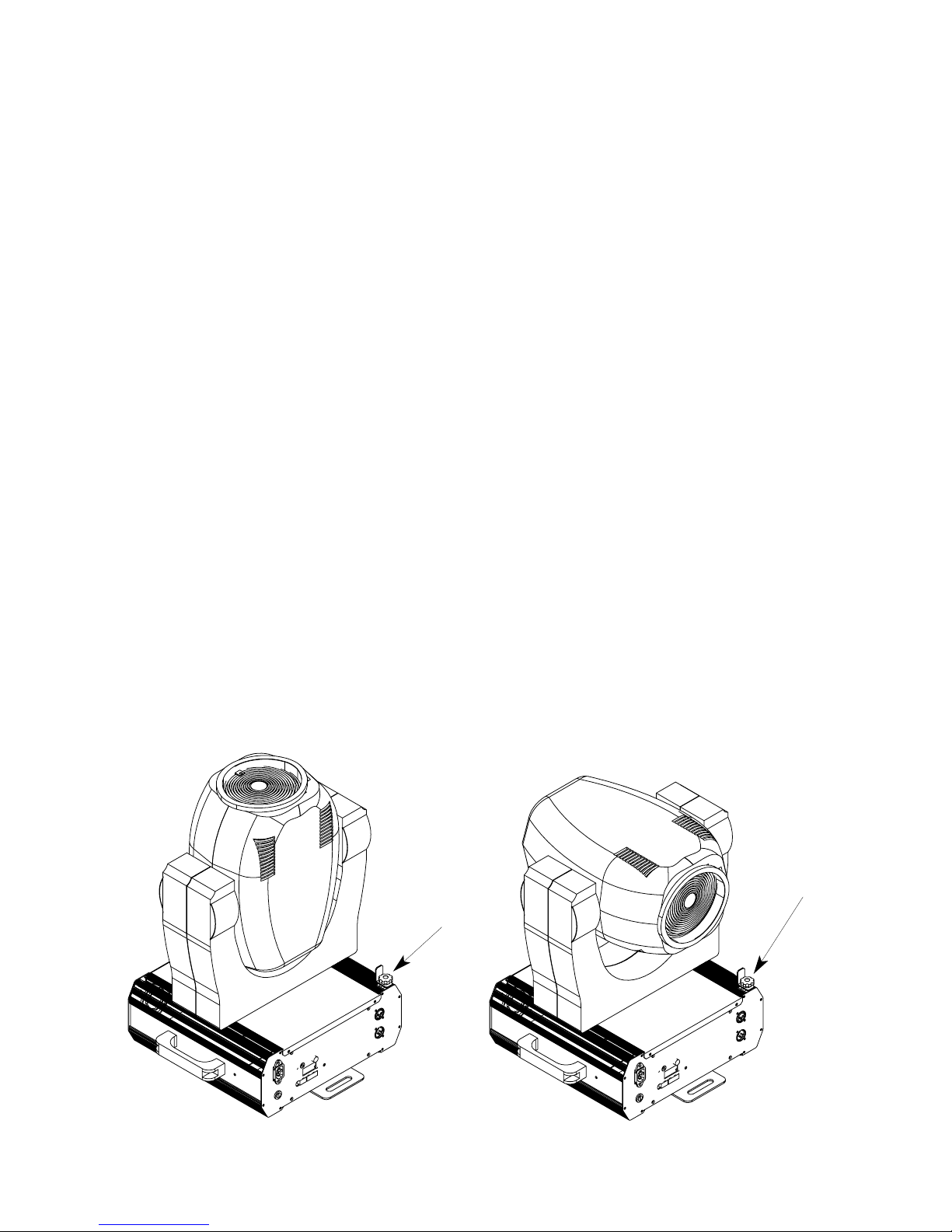
3.1 Rimozione dei fermi di sicurezza per il trasporto
Per evitare urti e movimenti che potrebbero causare danni al prodotto, durante il trasporto, ACRO-
BAT FE, è imballato con 2 fermi di sicurezza che assicurano la parte rotante al resto del proiettore.
Prima di utilizzare il proiettore è quindi necessaria la loro rimozione. Eseguire questa operazione
allentando 2 pomolini (indicati dalle frecce nelle figure 1 e 2) posti sulla parte cava del profilo late-
rale, far scorrere i fermi fino alle estremità del profilo stesso e riavvitare i pomolini.
fig. 1 fig. 2
3