Griven Jasper AL4360 User manual

Jasper
AL4360
Manuale di istruzioni
Instructions manual

I DEX
1.0 Introduction .................................................................................................................................16
1.1 S fety inform tion.......................................................................................................................................................16
1.1.1 Protecting g inst electric shock ..........................................................................................................................16
1.1.2 Inst ll tion ................................................................................................................................................................16
1.1.3 Protection g inst burns nd fire ...........................................................................................................................16
1.1.4 We ther protection..................................................................................................................................................16
1.2 Compli nce ................................................................................................................................................................16
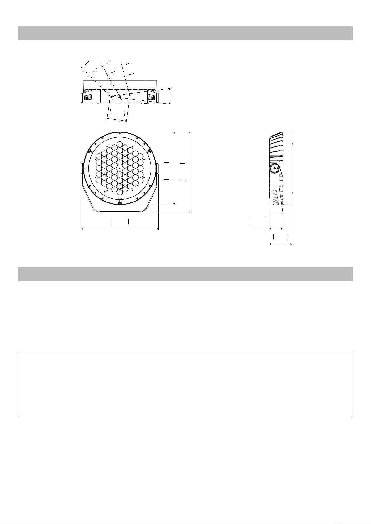
2.0 Size ...............................................................................................................................................17
3.0 Packaging and transport ...........................................................................................................17
3.1 P ck ging ...................................................................................................................................................................17
3.2 Tr nsport ......................................................................................................................................................................17
4.0 Installation ...................................................................................................................................18
4.1 Fixing ............................................................................................................................................................................18
4.2 Adjusting light be m direction..................................................................................................................................18
4.3 Connection to m ins power ......................................................................................................................................19
4.4 Connection to DMX sign l .........................................................................................................................................19
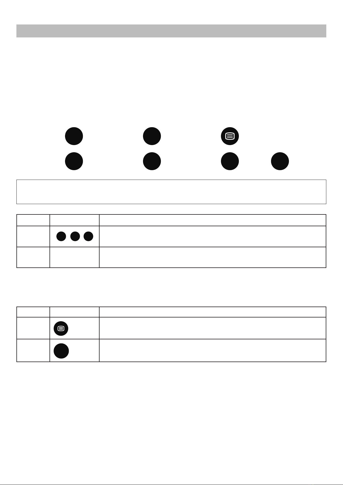
5.0 Use of the unit..............................................................................................................................20
5.1 Setting oper ting mode .............................................................................................................................................20
5.2 Setting DMX Address ..................................................................................................................................................20
5.3 DMX ddress setting with the ccessory Weezerd 1 ..............................................................................................20
5.4 Setting DMX mode .....................................................................................................................................................20
5.5 DMX functions RGBW ..................................................................................................................................................21
5.5.1 DMX functions with DMX MODE = 4 ch nnels.......................................................................................................21
5.5.2 DMX functions with DMX MODE = 5 ch nnels.......................................................................................................21
5.5.3 DMX functions with DMX MODE = 6 ch nnels.......................................................................................................21
5.6 DMX functions Dyn mic white...................................................................................................................................22
5.6.1 DMX functions with DMX MODE = 2 ch nnels.......................................................................................................22
5.6.2 DMX functions with DMX MODE = 3 ch nnels.......................................................................................................22
5.7 DMX functions monochrom tic ................................................................................................................................22
6.0 Master-Slave and Automatic function (RGBW e DW) .............................................................23
6.1 MASTER configur tion.................................................................................................................................................23
6.2 SLAVE configur tion RGBW ........................................................................................................................................24
6.3 SLAVE configur tion Dyn mic white.........................................................................................................................24
7.0 Fixed colours mode....................................................................................................................24
7.1 Fixed colours mode RGBW.........................................................................................................................................24
7.2 Fixed colour mode Dyn mic white...........................................................................................................................24
7.3 Monochrom tic fixed colour mode ........................................................................................................................24
7.4 SLAVE configur tion RGBW ........................................................................................................................................25
7.5 SLAVE configur tion Dyn mic white.........................................................................................................................25
7.6 SLAVE configur tion monochrome ...........................................................................................................................25
8.0 Thermal protection .....................................................................................................................25
9.0 o frost glass ...............................................................................................................................25
10.0 RDM functions............................................................................................................................25
11.0 Maintenance.............................................................................................................................26
11.1 Cle ning the unit ......................................................................................................................................................26
11.2 Regul r checks .........................................................................................................................................................26
12.0 Spare parts ................................................................................................................................26
13.0 Troubleshooting.........................................................................................................................26
14.0 Disposal......................................................................................................................................27
15.0 Technical specifications ..........................................................................................................27

1.1 Safety information
1.1.1 Protecting g inst electric shock
• Disconnect the unit from mains supply before servicing it or performing any other action.
• Always ground/earth the unit electrically.
• Before connecting the unit to power supplies, verify that operating voltage and frequency are compatible.
• Do not handle the unit with wet hands or in the presence of water.
• Check regularly that the power supply cable is not damaged or crushed.
• Apply to a qualified technician for any regular maintenance action not described in this manual.
1.1.2 Inst ll tion
• The unit installation actions must be performed by a qualified staff.
1.1.3 Protection g inst burns nd fire
• Suitable to be installed onto normally inflammable surfaces.
• The unit is not to be installed in places where the ambient temperature exceeds 50° (122°F).
1.1.4 We ther protection
The unit is classified as device with an IP66 weather protection rate.
1.2 Compliance
• Product in compliance with EN60598-1.
• Product in compliance with 2002/95/CE (RoHS).
1.0 Introduction
Warning!
This unit is suitable for professional use only, not for domestic use.
16 Italiano

3.1 Packaging
Check carefully the content of the box and, in case of damage, contact your forwarder immediately.
The following items are included in the box of this unit:
n° 1 Jasper unit
n° 1 owner’s manual
n° 2 connection kit
3.2 Transport
It is recommended to transport the unit with the maximum care, by using its original packing, to avoid to
damage the unit.
2.0 Size
19 1/2"
495
17 3/4"
Ø450
18 3/4"
477
3 1/8"
80
5 5/8"
142
15°
43/4"
120
3/8"
Ø10,50
1/4"
Ø6,50
1/4"
Ø6,50
3.0 Packaging and transport
Warning!
• Griven S.r.l. liability will cease upon consignment of goods to the forwarder: claims for damage due to trans-
port must be addressed directly to the forwarder.
• Griven S.r.l. will accept claims for broken or missing goods only within seven days of receipt of the goods.
• Returns of equipment will not be accepted without prior authorization granted by Griven S.r.l. and if not duly ac-
companied by relevant shipping documents.
Italiano 17

18 Italiano
4.1 Fixing
The unit can be used both rested on floor and fixed onto a structure. The unit can operate in any position.
Use the holes Ø10.5 (3/8”) or Ø6.5 (1/4”) in the bracket to fix the
unit.
4.2 Adjusting light beam direction
1. Untighten the lateral screw “1”.
2. Rotate the bodies of the unit towards desired direction and
tighten the screw “1”.
4.0 Installation
15°
43/4"
120
3/8"
Ø10,50
1/4"
Ø6,50
1/4"
Ø6,50
1

Italiano 19
4.3 Connection to mains power
The unit can operate with voltage from 100 to 277Vac and with frequency of 50 and 60Hz.
For the connection use main cable in the side of the rear boxl of the fixture and connect as shown below.
4.4 Connection to DMX signal
The DMX signal is to be connected by using a shielded cable designed for devices RS-485.
The signal cable must be connected according to the following table:
ND = Shield
DATA - = Black
DATA + = Red
The projector is fitted with butt connectors and heat shrink tube which allow to perform IP67 connections.
To make the connection follow these instructions.
Warning!
• Before connecting the unit, verify that power supplies features are compatible with the unit features.
• The unit must never be installed if not grounded electrically.
• It is suggested to use a magnetothermic switch along the power supply line, as prescribed by in force rules.
• The unit must not be powered up through a dimmer power device.
• Wiring and connection actions are to be performed by a qualified staff.
Live
Ground
Neutral
Brown
Yellow Green
Blue
Main supply
Warning!
Follow the instructions provided along with the connection kit to perform the connections.
Warning!
All data wires must be isolated one from another and from the shield.
The G D of the DMX signal is not to be connected to the electric ground of the unit.
Insert a terminal plug with a 120 Ω resistor connected to DATA- and DATA+ in the last unit.
Warning!
Follow the instructions provided along with the connection kit to perform the connections.

20 English
5.1 Setting operating mode
By using the infrared remote control AL1321 it is possible to select one of the following operating mode.
• using DMX512 signal control mode
Each fixture is controlled from DMX512 signal control.
• MASTER-SLAVE or AUTOMATIC mode
The projector operates independently, without DMX512 signal control. (see chapter 8)
Every button push is confirmed by a very short flash coming from the projector.
The following buttons will be used:
5.2 Setting DMX Address
By using the remote control (AL1321) it is possible to select the DMX address and mode:
5.3 DMX address setting with the accessory Weezerd 1
The DMX address can be set only by using the accessory AL2660 Weezerd 1. Refer to the manual of the
accessory.
5.4 Setting DMX mode with the accessory Weezerd 1
The DMX mode can be set only by using the accessory AL2660 Weezerd 1. Refer to the manual of the accessory.
5.0 Use of the unit
AV TELETEXT
1-/--
AV
79ʗ .....
10
PROG +
PROG -
P+
P-
Warning!
Before performing any setting operation it is necessary to log in as reported in the chart below.
Function Buttons Description
LO IN
123
It is the first procedure to be performed. After pushing the buttons 1, 2, 3 it is pos-
sible to access the functions settings. The function is confirmed by 1 white flash
coming from the projector.
LO OUT /The logout is automatic after 5 minutes of missing reception of the signal coming
from the remote control. Once th projector logs out it is not possible to perform
any other operation before a new login.
Funzione Tasti Descrizione
Change
of DMX
mode
+ 1 /.../ 6
Select the nuber of DMX channels. If the setting is correct then the projector will
confirm the procedure by performing 2 white flashes. (e.g. Projector R BW 5
channels, press 5)
Change
of DMX
address
+ 0....9
79ʗ
The new entered address must feature 3 digits (e.g. 0 6 7). If the address is correct
then the projector will confirm the procedure by performing 3 white flashes

English 21
5.5 DMX functions RGBW
5.5.1 DMX functions with DMX MODE = 4 ch nnels
5.5.2 DMX functions with DMX MODE = 5 ch nnels
5.5.3 DMX functions with DMX MODE = 6 ch nnels
DMX MODE CHA ELS USED (RGBW) CHA ELS USED (Dynamic white)
00 5 2
01 4 3
02 6 /
Channel Function Value Description
1 Red 0-255 Proportional control 0-100% of the Red color
2 reen 0-255 Proportional control 0-100% of the reen color
3 Blue 0-255 Proportional control 0-100% of the Blue color
4 White 0-255 Proportional control 0-100% of the White color
Channel Function Value Description
1 Red 0-255 Proportional control 0-100% of the Red color
2 reen 0-255 Proportional control 0-100% of the reen color
3 Blue 0-255 Proportional control 0-100% of the Blue color
4 White 0-255 Proportional control 0-100% of the White color
5Dimmer
Strobe
0-15 Luminous output intensity 100%
16-150 Proportional control of the luminous output intensity 100-0%
151-160 Luminous output intensity 0%
161-255 Proportional control of the strobe effect 0-100% (255=max)
Channel Function Value Description
1 Red 0-255 Proportional control 0-100% of the Red color
2 reen 0-255 Proportional control 0-100% of the reen color
3 Blue 0-255 Proportional control 0-100% of the Blue color
4 White 0-255 Proportional control 0-100% of the White color
5 Dimmer
0-5 Luminous output intensity 0%
6-250 Proportional control of the luminous output intensity 0-100%
251-255 Luminous output intensity 100%
6 Strobe
0-15 No strobe
6-250 Proportional control of the strobe effect 0-100%
251-255 Strobe effect 100%

22 English
5.6 DMX functions Dynamic white
5.6.1 DMX functions with DMX MODE = 2 ch nnels
5.6.2 DMX functions with DMX MODE = 3 ch nnels
5.7 DMX functions monochromatic
Warning!
In absence of DMX signal the led will remain O .
Channel Function Value Description
1Dynamic
white
0-3 Warm white 100% - Cold white 0%
4-122 Warm white 100% - Cold white from 0% to 100%
123-132 Warm white 100% - Cold white 100%
133-251 Warm white 100% to 0% - Cold white 00%
252-255 Warm white 0% - Cold white 100%%
2Dimmer
Strobe
0-15 Luminous output intensity 100%
16-150 Proportional control of the luminous output intensity 100-0%
151-160 Luminous output intensity 0%
161-255 Proportional control of the strobe effect 0-100% (255=max)
Channel Function Value Description
1Warm
white 0-255 Proportional control 0¬-100% of the warm white
2Cold
white 0-255 Proportional control 0¬-100% of the cold white
3Dimmer
Strobo
0-15 Luminous output intensity 100%
16-150 Proportional control of the luminous output intensity 100-0%
151-160 Luminous output intensity 0%
161-255 Proportional control of the strobe effect 0-100% (255=max)
Attention!
In absence of DMX signal the led will remain O .
Channel Function Value Description
1Dimmer
Strobe
0-15 Luminous output intensity 100%
16-150 Proportional control of the luminous output intensity 100-0%
151-160 Luminous output intensity 0%
161-255 Proportional control of the strobe effect 0-100% (255=max)

English 23
Jasper can operate without DMX signal (in AUTOMATIC mode) and can be set so that a single MASTER unit will
command a series of SLAVE units. This function is particularly useful when more units are desired to execute the
same programme in synchrony.
The following picture shows an example of a Master-Slave layout.
6.1 MASTER configuration
The projector can perform a pre-set colour-changer programme.
In order to perform such pre-set programme please refer to the chart below:
The projector will perform a flash if you select a time of 5 seconds, 2 flashes for 10 seconds, 3 flashes for 20 sec-
onds and 4 flashes for 40 seconds.
6.0 Master-Slave and Automatic function (RGBW and DW)
MASTER SLAVE 1 SLAVE N
INOUTINOUT
SLAVE 2
INOUT
Terminal resistor
(R=120 ƺnot included!)
Funzione Tasti Descrizione
Master Con-
figuration
AV
the input or the removing of the automatic mode can be performed only after
the log in. The programme is: green-cyan-blue-magenta-red-yellow-white. The
pre-set time of each scene is 5 seconds. If the projector is turned off when it is set
in automatic mode, it will switch on again in automatic mode with the same se-
lected scene time.
Increase of
the scene
duration
P+
Available only if the projector is set in automatic mode. Increase of the scene
time: 5 – 10 – 20 – 40 seconds.
Decrease
of the
scene du-
ration
P-
Available only if the projector is set in automatic mode. Decrease of the scene
time: 40 – 20 – 10 – 5 seconds.
Warning!
If MASTER-SLAVE mode is being used, no other DMX control device must be present along the line!!

24 English
6.2 SLAVE configuration RGBW
To set up the unit as SLAVE set the 5 channels DMX mode with address 001.
6.3 SLAVE configuration Dynamic white
To set up the unit as SLAVE set the 3 channels DMX mode with address 001.
In the FIXED COLOURS mode, it is possible to manually turn on the LEDs, without the use of a DMX.
In this mode, the projector also behaves as a master and can control a number of projectors SLAVE.
7.1 Fixed colours mode RGBW
7.2 Fixed colour mode Dynamic white
7.3 Monochromatic fixed colour mode
7.0 Fixed colours mode
Function Keys Description
Fixed
colours
mode input
The preset colours mode is activated or deactivated by the (TV) key.
Colour se-
lection 1 / 2 / 3 / 4 Select the colour whose intensity is intended to be adjusted by the keys from 1 to
4 (1=red; 2=green; 3=blue; 4=white).
Colour
intensity
+ -
The intensity of the selected colour, with a 10% increase or decrease, is adjusted
by the VOL+ and VOL- keys.
Function Keys Description
Fixed
colours
mode input
The preset colours mode is activated or deactivated by the (TV) key.
Colour se-
lection 4 / 5 Select the colour whose intensity is intended to be adjusted by the keys 4 or 5
(4=cold white; 5=warm white).
Colour
intensity
+ -
The intensity of the selected colour, with a 10% increase or decrease, is adjusted
by the VOL+ and VOL- keys.
Function Keys Description
Dimmer
function The dimmer mode is activated or deactivated by the (AV) key.
White
colour
intensity
+ -
The intensity of the white colour is adjusted by the VOL+ and VOL- keys by
256 steps.

English 25
7.4 SLAVE configuration RGBW
To set up the unit as SLAVE set the 5 channels DMX mode with address 001.
7.5 SLAVE configuration Dynamic white
To set up the unit as SLAVE set the 3 channels DMX mode with address 001.
7.6 SLAVE configuration monochrome
To set up the unit as SLAVE set DMX mode with address 001.
An internal temperature sensor prevents the unit from overheating. The temperature sensor will limit the current
to leds, protecting their integrity, if the ambient temperature exceeds the one allowed.
The POLAR Edition of the projector is fitted with a thermal glass which is particularly useful for outdoor applications.
In fact, by warming up the glass melts ice and snow which might interfere with the projection.
When the projector is on, if required by the weather conditions, the glass is automatically warmed up.
If the projection is to be started at a definite time, take care to defrost the glass in advance so that the leds can
be lit at the time required.
With very cold temperatures (below -20° C), we recommend you to let the projector always powered and switch
on the LEDs when needed.
When operating in DMX mode, the projector can accept the following RDM commands:
• discovery
Upon request of the RDM controller, the projector adverts its own presence (the RDM controller will display the
projector between a list).
• DMX address reading and setting.
• Channels number reading and setting.
• On / Off identification
This command is used to identify the projector you want to get access to (the identification happens by swit-
ching on at full intensity all the LEDs).
• Manufacturer
The name of the manufacturer ( riven) is displayed.
• Model description
The projector model is displayed.
• Software version description
The version of the firmware in use on the projector (v.x.xx) is displayed.
• Temperature
The LEDs operating temperature value is displayed.
10.0 RDM functions
8.0 Thermal protection
9.0 o frost glass

26 English
To ensure maximum functionality and light output it is recommended to follow these instructions:
11.1 Cleaning the unit
The unit must be cleaned regularly. Cleaning regularity will depend especially on the environment where the unit
will operate: deposits of dust, smokes or other wastes will reduce the light output performances.
• Clean regularly the glass of the unit.
• Do not use solvents which could damage painted surfaces.
11.2 Regular checks
• Check electrical connections, especially the ground wiring and the power supply cable.
• Check that the unit is not damaged mechanically. Replace those components which have got deteriorated
Replace damaged protection shields.
All components of the unit are available as spare parts at Griven dealers.
Exploded views, wiring diagrams, electronic layouts and advertising brochures are available on request.
To make the job of assistance centres easier, specify serial number and model of the unit which spare parts are
requested for.
Inconvenience Possibile Cause Action
The unit does not
respond properly
to the DMX control.
Incorrect DMX cable
connection.
Check connections and wires. Rectify inefficient connec-
tions. Repair or replace damaged wires.
Unfinished data connection.
Insert a terminal resistor in the terminal box of the last
unit of the connection.
Incorrect address
assignment to the units. Check the addresses of the units and the protocol settings.
One of the unit is faulty and
it is affecting the data
transmission along the
connection.
Short-circuit units singularly, one by one,
since regular working is restored.
The unit is set to Slave,
but does not
respond properly
to the Master.
There more than a unit is set
to Master.
Check that amongst the interconnected fixtures, only one
has been set to Master.
Conflict in signals. Ensure that there is no incoming DMX signal.
12.0 Spare parts
13.0 Troubleshooting
11.0 Maintenance
Attention!
Always remove mains power prior to opening up the fixture.

English 27
The European Directive 2002/96/EC on Waste Electrical and Electronic Equipment (WEEE), requires that old
lighting fixtures must not be disposed of the normal unsorted municipal waste stream. Old appliances must be
collected separately in order to optimise the recovery and recycling of the materials they contain and reduce
the impact on human health and the environment.
The crossed out “wheeled bin” symbol on the product reminds you of your obligation, that
when you dispose of the appliance it the must be separately collected.
Consumer should contact their local authority or retailer for information concerning the correct disposal of their
old appliance.
Mechanical features
Height . . . . . . . . . . . . . . . . . . . . . . . . . . . . . . . . . . . . . . . . . . . . . . . . . . . . . . . . . . . . . . . . . . . . . . . . . . . . .495mm (19 1/2”)
Width . . . . . . . . . . . . . . . . . . . . . . . . . . . . . . . . . . . . . . . . . . . . . . . . . . . . . . . . . . . . . . . . . . . . . . . . . . . . . 477mm (18 3/4”)
Depth . . . . . . . . . . . . . . . . . . . . . . . . . . . . . . . . . . . . . . . . . . . . . . . . . . . . . . . . . . . . . . . . . . . . . . . . . . . . . 142mm (5 5/8”)
Weight . . . . . . . . . . . . . . . . . . . . . . . . . . . . . . . . . . . . . . . . . . . . . . . . . . . . . . . . . . . . . . . . . . . . . . . . . . . . . 18Kg (39.7Lbs)
Thermal features
Minimum ambient temperature . . . . . . . . . . . . . . . . . . . . . . . . . . . . . . . . . . . . . . . . . . . . . . . . . . . . . . . . . . -40°C (-40°F)
Maximum ambient temperature . . . . . . . . . . . . . . . . . . . . . . . . . . . . . . . . . . . . . . . . . . . . . . . . . . . . . . . . . . 50°C (122°F)
Maximum surface temperature . . . . . . . . . . . . . . . . . . . . . . . . . . . . . . . . . . . . . . . . . . . . . . . . . . . . . . . <60°C ( <140°F)
Electrical features
Voltage . . . . . . . . . . . . . . . . . . . . . . . . . . . . . . . . . . . . . . . . . . . . . . . . . . . . . . . . . . . . . . . . . . . . . . . 100-277 Vac 50/60Hz
Nominal current . . . . . . . . . . . . . . . . . . . . . . . . . . . . . . . . . . . . . . . . . . . . . 0.88A @ 230V (1.41A @ 230V Polar version)
Maximum power . . . . . . . . . . . . . . . . . . . . . . . . . . . . . . . . . . . . . . . . . . . . . . . . . . . . . . . . . . 195W ( 315W Polar version)
Thermal protection . . . . . . . . . . . . . . . . . . . . . . . . . . . . . . . . . . . . . . . . . . . . . . . . . . . . . . . . . . . . . . . . . . . . . . . Electronic
Light output source
Type of light output source . . . . . . . . . . . . . . . . . . . . . . . . . . . . . . . . . . . . . . . . . . . . . . . . . . . . . . . . . . . . . . . . . . . 60 Leds
Optics
Optical system . . . . . . . . . . . . . . . . . . . . . . . . . . . . . . . . . . . . . . . . . . . . . . . . . . . . . . . . . . . . . . . . . . . . . . . . . . . . . Lenses
Control
Protocol . . . . . . . . . . . . . . . . . . . . . . . . . . . . . . . . . . . . . . . . . . . . . . . . . . . . . . . . . . . . . . . . . . . . . . . . . . . . . USITT DMX-512
Control channels R BW . . . . . . . . . . . . . . . . . . . . . . . . . . . . . . . . . . . . . . . . . . . . . . . . . . . . . . . . . . 4-5-6 DMX channels
Control channel Dynamic white . . . . . . . . . . . . . . . . . . . . . . . . . . . . . . . . . . . . . . . . . . . . . . . . . . . . . 2-3 DMX channels
Control channel Monochromatic . . . . . . . . . . . . . . . . . . . . . . . . . . . . . . . . . . . . . . . . . . . . . . . . . . . . . . 1 DMX channel
Construction
Unit body . . . . . . . . . . . . . . . . . . . . . . . . . . . . . . . . . . . . . . . . . . . . . . . . . . . . . . . . . . . . . . . . . . . stainless steel/Aluminium
Treatment . . . . . . . . . . . . . . . . . . . . . . . . . . . . . . . . . . . . . . . . . . . . . . . . . . . . . . . . . . . . . . . Scratch resistant black paint
Weather protection rating . . . . . . . . . . . . . . . . . . . . . . . . . . . . . . . . . . . . . . . . . . . . . . . . . . . . . . . . . . . . . . . . . . . . . . IP66
Impact rating . . . . . . . . . . . . . . . . . . . . . . . . . . . . . . . . . . . . . . . . . . . . . . . . . . . . . . . . . . . . . . . . . . . . . . . . . . . . . . . . . IK10
15.0 Technical specifications
14.0 Disposal

Via Bulgaria, 16 - 46042 CASTEL OFFREDO (MN) - Italy
Telefono 0376/779483 - Fax 0376/779682 - 0376/779552
http://www.griven.com/ e-mail [email protected]
http://www.griven.it/ e-mail [email protected]
User’s manual rel. 1.00
Table of contents
Other Griven Dj Equipment manuals

Griven
Griven Graph-i-Core AL2115 User manual

Griven
Griven HELIOS MK2 Series User manual

Griven
Griven ACROBAT FE User manual

Griven
Griven PARADE i-PIX User manual

Griven
Griven Parade L MC 1 User manual

Griven
Griven Graph-i-Dot AL4700 User manual

Griven
Griven ACROBAT PE 575 Manual

Griven
Griven Jasper MK2 User manual

Griven
Griven Parade LB1 User manual

Griven
Griven GR0632 User manual