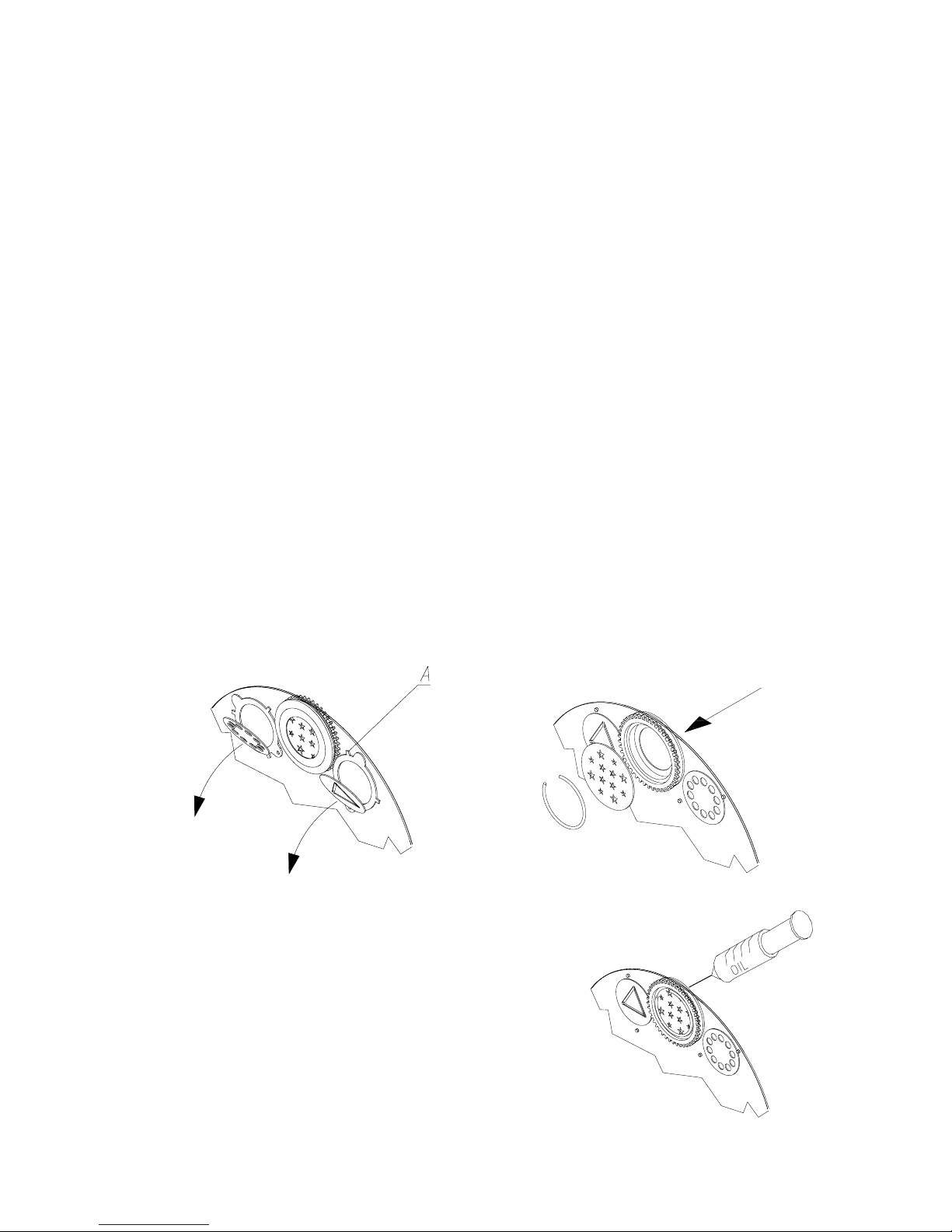
3.2 Montaggio della lampada
1) Aprite lo sportello cambio-lampada svitando le 2 viti M4 (indicate con le freccie A) situate
nella parte posteriore della testa del proiettore (vedi fig. 1, 2 e 3).
2) Dopo averla sgrassata con l’apposita salvietta detergente, inserite la lampada nel portalam-
pada con le dovute precauzioni:
- non toccate la lampada con le dita e con stracci unti o comunque sporchi;
- non scuotete la lampada e non fatela urtare contro la lamiera del proiettore o altri oggetti;
3) Fissate saldamente la lampada al portalampada.
4) Richiudete lo sportello cambio-lampada.
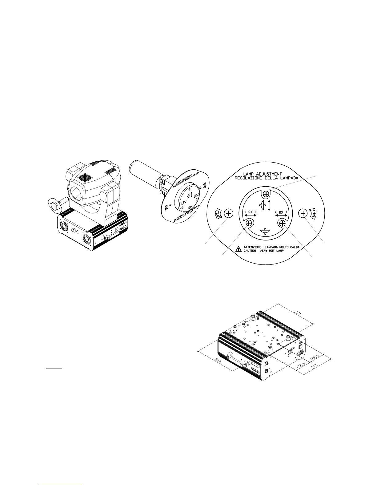
5) Può capitare, che accendendo il proiettore il fascio luminoso non sia ben uniforme, questo si
verifica quando la lampada è leggermente diversa da quella utilizzata in precedenza. E’ possi-
bile regolare la messa a punto: agire sulle 3 viti M4 (B fig.3) poste sullo sportello cambio-lam-
pada. Continuate la regolazione finche non ottenete una proiezione del fascio uniforme.
3.3 Posizionamento del proiettore
ACROBAT PE 575 è dotato di una piastra d’appoggio che permette una stabile collocazione a
terra, ma può essere montato in qualsiasi posizione, mantenendo una distanza dalla parete o
dalle pareti di almeno 50cm per favorire la libera circolazione dell’aria intorno al proiettore e
contenerne il riscaldamento.
3.4 Fissaggio del proiettore
Per il fissaggio del proiettore a terra, a parete, o al
soffitto utilizzate la piastra alla base del proiettore,
provvista di 6 inserti M10 e interassi rappresentati
in fig.4.
Nota: E’ possibile rimuovere i gommini di soste-
gno prima di fissare il proiettore tramite gli inserti.
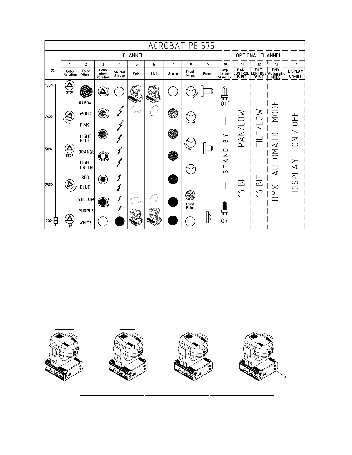
3.5 Collegamento elettrico
1) Cablate la spina fornita con un cavo di alimentazione di sezione 3x1.5mm2minimo.
2) Collegate alla rete facendo attenzione alla tensione di alimentazione (230V - 50/60Hz).
3) La linea di alimentazione del proiettore deve essere protetta mediante corretta messa a terra
e interruttore magnetotermico differenziale avente le seguenti caratteristiche:
- Corrente nominale (In) 10A - Valore d’intervento (Id) 0,03 A.
4) Questo proiettore dispone di rifasatore di corrente.
4
fig.1 fig.2 fig.3
fig.4
AA
B
B
B