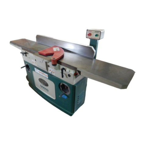
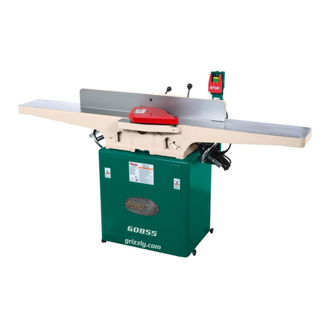
Grizzly G0609X User manual

WARNING: NO PORTION OF THIS MANUAL MAY BE REPRODUCED IN ANY SHAPE
OR FORM WITHOUT THE WRITTEN APPROVAL OF GRIZZLY INDUSTRIAL, INC.
If you have any further questions about this manual insert or the differences between the Model
and the Model , contact our Technical Support at (570) 546-9663 or email techsupport@grizzly.
com.
MODEL G0609X
12" JOINTER
w/SPIRAL CUTTERHEAD
MANUAL INSERT

The information contained herein is deemed accurate as of 6/30/2008 and represents our most recent product specifications.
Due to our ongoing improvement efforts, this information may not accurately describe items previously purchased. PAGE 1 OF 2Model G0609X
MACHINE DATA
SHEET
Customer Service #: (570) 546-9663 · To Order Call: (800) 523-4777 · Fax #: (800) 438-5901
MODEL G0609X 12" JOINTER W/ SPIRAL CUTTERHEAD
Product Dimensions:
Weight.............................................................................................................................................................. 884 lbs.
Length/Width/Height....................................................................................................................... 84 x 33 x 43-1/2 in.
Foot Print (Length/Width)....................................................................................................................... 44-1/4 x 18 in.
Shipping Dimensions:
Type........................................................................................................................................................... Wood Crate
Content............................................................................................................................................................ Machine
Weight............................................................................................................................................................ 1045 lbs.
Length/Width/Height...........................................................................................................88-3/8 x 29-3/4 x 40-1/2 in.
Electrical:
Switch.......................................................................................................Magnetic with Thermal Overload Protection
Switch Voltage...................................................................................................................................................... 220V
Cord Length............................................................................................................................................................ 5 ft.
Cord Gauge....................................................................................................................................................12 guage
Recommended Breaker Size............................................................................................................................ 20 amp
Plug.......................................................................................................................................................................... No
Motors:
Main
Type.................................................................................................................. TEFC Capacitor Start Induction
Horsepower.................................................................................................................................................3 HP
Voltage........................................................................................................................................................220V
Prewired......................................................................................................................................................220V
Phase........................................................................................................................................................ Single
Amps.............................................................................................................................................................15A
Speed.................................................................................................................................................3450 RPM
Cycle..........................................................................................................................................................60 Hz
Number Of Speeds........................................................................................................................................... 1
Power Transfer .........................................................................................................................................V-Belt
Bearings....................................................................................................................... Shielded and Lubricated
Main Specifications:
Fence Information
Fence Length....................................................................................................................................... 46-3/4 in.
Fence Width........................................................................................................................................... 1-1/2 in.
Fence Height..........................................................................................................................................5-3/8 in.
Fence Stops................................................................................................................................ 45 and 90 deg.
Cutting Capacities
Bevel Jointing.....................................................................................................................................90-45 deg.
Maximum Width of Cut............................................................................................................................... 12 in.
Maximum Depth of Cut..............................................................................................................................1/8 in.
Maximum Rabbiting Depth........................................................................................................................ 3/4 in.
Number of Cuts Per Minute.......................................................................................................................19800
The information contained herein is deemed accurate as of 6/30/2008 and represents our most recent product specifications.
Due to our ongoing improvement efforts, this information may not accurately describe items previously purchased. PAGE 2 OF 2Model G0609X
Cutterhead Information
Cutterhead Type........................................................................................................................................ Spiral
Cutterhead Diameter..............................................................................................................................3-7/8 in.
Number of Cutter Spirals...................................................................................................................................4
Number of Indexable Cutters.......................................................................................................................... 60
Cutter Insert Type................................................................................................................................Indexable
Cutter Insert Length................................................................................................................................. 14 mm
Cutter Insert Width................................................................................................................................... 14 mm
Cutter Insert Thickness.............................................................................................................................. 2 mm
Cutterhead Speed.............................................................................................................................. 4950 RPM
Table Information
Table Length........................................................................................................................................ 83-1/2 in.
Table Width.......................................................................................................................................... 12-3/4 in.
Table Thickness..........................................................................................................................1-7/8 - 3-1/4 in.
Floor to Table Height........................................................................................................................31-11/16 in.
Table Adjustment Type..................................................................................................................... Handwheel
Table Movement Type.................................................................................................................. Parallelogram
Construction
Base Construction................................................................................................................................ Cast Iron
Body Assembly Construction................................................................................................................Cast Iron
Cabinet Construction............................................................................................................................ Cast Iron
Fence Assembly Construction..............................................................................................................Cast Iron
Guard Construction.............................................................................................................. Moulded Aluminum
Table Construction...................................................................................................Precision Ground Cast Iron
Parallelogram................................................................................................................................................Yes
Paint........................................................................................................................................... Powder Coated
Other Information
Number of Dust Ports........................................................................................................................................1
Dust Port Size.............................................................................................................................................. 5 in.
Other Specifications:
Country Of Origin ................................................................................................................................................China
Warranty ............................................................................................................................................................ 1 Year
Serial Number Location .............................................................................................. Data Label on Front of Cabinet
Assembly Time ........................................................................................................................................... 45 minutes
Features:
Parallelogram Beds
Top Mount Switch Controls
5 3/8" Tall Fence
Included Push Blocks
5" Dust Port
Spiral Cutterhead with German-Made Indexable Carbide Inserts

<gdjcY
HiVgi
8VeVX^idg
'*%B;9
'*%K68
Gjc
8VeVX^idg
)%B;9
)*%K68
7`
7`
7`
7`
GY
GY
GY
7`
7`
<c
MOTOR
Li
&A& (A' *A(
'I& )I' +I(
'I& )I' +I(
&(cd
&)cd
6'
.-
6'
6&
., .+ .*
=di
<gdjcY
=di
7A68@
L=>I:
<G::C
G:9
7AJ:
COLOR KEY
7`
Li
<c
GY
7a
<gdjcY
=di
=di
L6-20 PLUG
(as recommended)
220 VAC
CONTROL PANEL
k^ZlZY[gdbWZ]^cY
WARNING!
SHOCK HAZARD!
Disconnect power
before working on
wiring.
<c
HI6GI
HIDE
GY
GY
GY GYGY
GY
GY
GY
GY
7a
7a
7`
7`
<c
7`
7`
Li
Li
Li
MAGNETIC
SWITCH
ASSEMBLY
8dciVXidg
I]ZgbVaGZaVn
7`
7`
GY
GY
GY
GY
7a Li
7` <c
Li
Li
<c
<c <c
Li
Li
<c
7` Li
7`
<c
Li
Li
GY
GY GY
GY
G0609X 220V Wiring Diagram

&
)
*
+
.
&%
&&
()
(+
(,
(-
(.
)%
)&
)' )(
))
)*
)+
),
)-
). *% *&
*'
*(
*)
*+
*,
*- *.
+% +& +'
,
-
&'
&(
&*
&+
&)
&-
&.
'%
&,
'&
'(
',
(%
'-
'.
(&
('
((
(*
+(
+)
+*
-'
-&
-%
,.
,-
,,
)'"&
)'"'
-)
-*
,(
-+
-,
--
**"&
**
,+
,)
,(
,'
,&
,%
+.
+-
++
+,
,*
'+ ')
'* ''
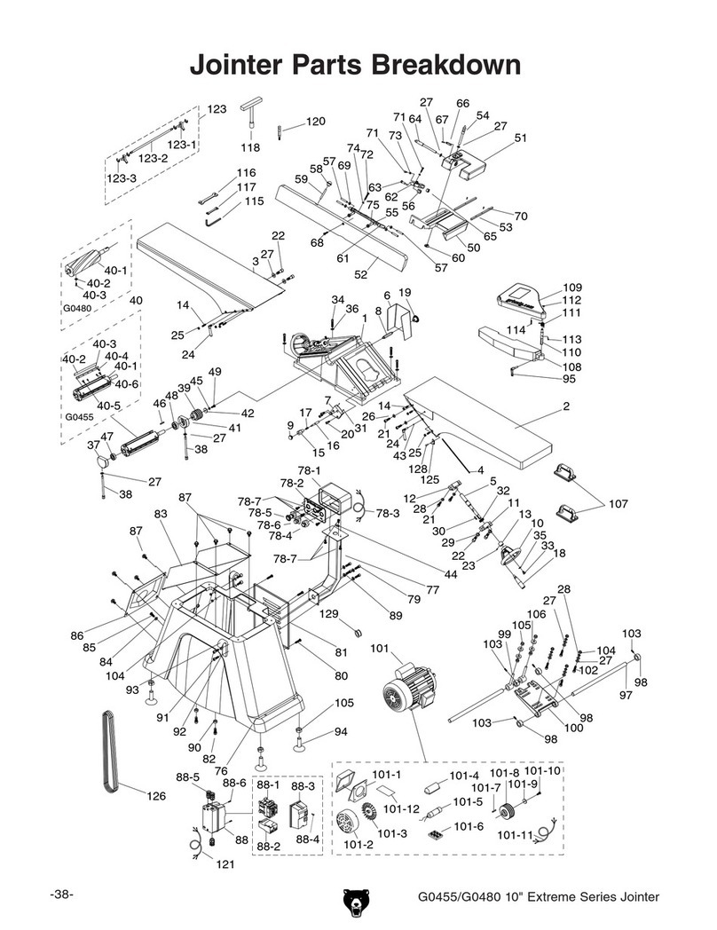
Jointer Breakdown

REF PART # DESCRIPTION REF PART # DESCRIPTION
1 P0609001 CUTTERHEAD GUARD 45 P0609045 SHAFT
4 PFH23M FLAT HD SCR M8-1.25 X 16 46 PLW06M LOCK WASHER 10MM
5 P0609005 SPECIAL FLAT WASHER 47 PB32M HEX BOLT M10-1.5 X 25
6 PSS04M SET SCREW M6-1 X 12 48 P0609048 BUSHING
7 P0609007 ADAPTER 49 P0609049 WORM GEAR
8 P0609008 TORSION SPRING 50 PK12M KEY 5 X 5 X 30
9 P0609009 SHAFT COLLAR 51 P0609051 GEAR
10 PSS04M SET SCREW M6-1 X 12 52 P0609052 WORM
11 P0609011 SHAFT 53 PK37M KEY 4 X 4 X 16
12 P0609012 CUTTERHEAD SCREW 54 P0609054 SLIDE STOP BLOCK
13 PLW06M LOCK WASHER 10MM 55 P0609055 SLIDE STOP BLOCK
14 PW04M FLAT WASHER 10MM 55-1 PSS16M SET SCREW M8-1.25 X 10
15 PK111 KEY 8 X 8 X 60 56 P0609056 SPECIAL FLAT SCREW
16 P0609016 CUTTERHEAD PULLEY 57 P0609057 POINTER
17 PVA53 V-BELT A-53 4L530 58 PW02M FLAT WASHER 5MM
18 PSB02M CAP SCREW M6-1 X 20 59 PS09M PHLP HD SCR M5-.8 X 10
19 P0609019 BEARING COVER 60 PB73M HEX BOLT M10-1.5 X 50
20 P6206 BALL BEARING 6206ZZ 61 P0609061 CLAMP BLOCK
21 P0609021 BEARING SUPPORT 62 PLW06M LOCK WASHER 10MM
22 P0452Z001 DRIVER BIT TORX T20 63 PW04M FLAT WASHER 10MM
23 P0609X023 SPIRAL CUTTERHEAD 12" 64 P0609064 CLAMPING BLOCK
24 P0452Z002 INDEXABLE INSERT 14 x 14 x 2 65 P0609065 CLAMP PLATE
25 P0452Z009 L-WRENCH TORX T20 66 PHTEK4M TAP SCREW M4 X 8
26 PFH35M FLAT HD TORX SCR T20 M6-1 X 15 67 P0609067 STOP BUTTON
27 P0609027 BEARING SUPPORT 68 P0609068 START BUTTON
28 P62042RZ BALL BEARING 62042RZ 69 P0609069 SWITCH BOX
29 PW01M FLAT WASHER 8MM 70 PFS14M FLANGE SCREW M8-1.25 X 16
30 P0609030 CUTTERHEAD SCREW 71 P0609071 SWITCH BOX BRACKET
31 PN02M HEX NUT M10-1.5 72 PB32M HEX BOLT M10-1.5 X 25
32 P0609032 BEARING COVER 73 PLW06M LOCK WASHER 10MM
33 PSB02M CAP SCREW M6-1 X 20 74 PW04M FLAT WASHER 10MM
34 PB156 HEX BOLT M10-1.5 X 150 75 P0609075 BUTTON PLATE
35 PSS71M SET SCREW M10-1.5 X 60 76 P0609076 BALL STRAIN RELIEF
36 P0609036 BASE 77 PAW10M HEX WRENCH 10MM
37 PSS04M SET SCREW M6-1 X 12 78 PAW08M HEX WRENCH 8MM
38 PW04M FLAT WASHER 10MM 79 PAW03M HEX WRENCH 3MM
39 P0609039 LOCK HANDLE 80 PWR1719 WRENCH 17 X 19
40 PSS03M SET SCREW M6-1 X 8 81 PWR1214 COMBO WRENCH 12/14MM
41 P0609041 ECCENTRIC BUSHING 82 PWR1012 COMBO WRENCH 10/12MM
42 P0609042 SHAFT 84 P0609084 BUSHING
42-1 P0609042-1 LEFT TORSION SPRING 85 P6202 BALL BEARING 6202ZZ
42-2 P0609042-2 RIGHT TORSION SPRING 86 PB06M HEX BOLT M8-1.25 X 12
43 P0609043 STOP BLOCK 87 PW03M FLAT WASHER 6MM
44 PR21M INT RETAINING RING 35MM 88 PB02M HEX BOLT M6-1 X 12
Jointer Breakdown Parts List

&%&
&%'
&%(
&%)
&%, &%+
&%*
&%-
&%.
&&%
&&& &&'
&&+
&&*
&'%
&&,
&&-
&&.
&&)
&&(
Tables Breakdown
REF PART # DESCRIPTION REF PART # DESCRIPTION
101 P0609101 TABLE (LEFT) 111 PSB72M CAP SCREW M10-1.5 X 30
102 P0609102 TABLE LIP (LEFT) 112 PLW06M LOCK WASHER 10MM
103 PLW06M LOCK WASHER 10MM 113 P0609113 DEPTH SCALE
104 PSB84M CAP SCREW M10-1.5 X 35 114 P0609114 RIVET 2 X 4
105 P0609105 SHAFT 115 PW03M FLAT WASHER 6MM
106 P0609106 TABLE (RIGHT) 116 PSB04M CAP SCREW M6-1 X 10
107 P0609107 TABLE LIP (RIGHT) 117 P0609117 DUST DEFLECTOR
108 PSB84M CAP SCREW M10-1.5 X 35 118 PSB38M CAP SCREW M5-.8 X 25
109 PLW06M LOCK WASHER 10MM 119 P0609119 STOP BLOCK
110 P0609110 RABBETING ARM 120 P0609120 BAR

'%&
'%'
'%(
'%)
'%*
'%+
'%,
'&%
'&(
'&&
'&'
'&)
'&*
'&+
'&,
'&-
'&.
''%
''& '''
''(
'')
''*
''+
'(*
'(,
'',
''-
''.
'(%
'(&
'('
'((
'()
'(+
'(-
'(.
')%
')&
')'
')(
')*
Fence Breakdown
REF PART # DESCRIPTION REF PART # DESCRIPTION
201 P0609201 FENCE BRACKET 224 P0609224 SPECIAL HEX NUT M12
202 PW06M FLAT WASHER 12MM 225 P0609225 LEFT BRACKET
203 PLW05M LOCK WASHER 12MM 226 P0609226 PIN
204 PSB77M CAP SCREW M12-1.75 X 30 227 P0609227 HANDLE
205 P0609205 SLIDING RAIL 228 P0609228 HANDLE ROD
206 PSB20M CAP SCREW M5-.8 X 14 229 PN09M HEX NUT M12-1.75
207 P0609207 SLIDING BRACKET 230 P0609230 FENCE
210 P0609210 BLOCK 231 P0609231 CLAMP
211 PW01M FLAT WASHER 8MM 232 PSB64M CAP SCREW M10-1.5 X 25
212 PB07M HEX BOLT M8-1.25 X 25 233 P0609233 LOCK LEVER ASSY
213 P0609213 COLLAR 234 P0609234 SPECIAL FLAT WASHER
214 PSS14M SET SCREW M8-1.25 X 12 235 P0609235 DOUBLE END THREADED ROD
215 PSS04M SET SCREW M6-1 X 12 236 PRP03M ROLL PIN 5 X 20
216 PB30M HEX BOLT M8-1.25 X 55 237 P0609237 SPECIAL NUT M12
217 PN03M HEX NUT M8-1.25 238 P0609238 SUPPORT BRACKET
218 P0609218 COLLAR 239 PB09M HEX BOLT M8-1.25 x 20
219 P0609219 ECCENTRIC SHAFT 240 PN03M HEX NUT M8-1.25
220 P0609220 HANDLE ROD 241 P0609241 RIGHT BRACKET
221 P0609221 HANDLE 242 PN03M HEX NUT M8-1.25
222 P0609222 SLIDING BUSHING ASSY 243 PB20M HEX BOLT M8-1.25 X 35
223 PW06M FLAT WASHER 12MM 245 P0609245 RIVET 2 X 5

(%&"&
(%&
(%* (%+
(%,
(%-
(%.(&%
(&&
(&'
(&(
(&)
(&*"&
(&+
(&,
(&-
('%
(&.
('&
(''
('(
(')
('*
('+
(',
('-
('.
((%
((&
((,
((+
((*
(()
(((
(('
((-
((.
()%
()&
()'
()(
())
()*
()+
(),
(*%
().
()-
(&*K'
(()"&
(()"'
(()"(
(()")
(()"*
(%)
(%&"'
(*&
(%'
(%'"&
(*'
(&*"(K'
(&*"'K'
(&*")K'
(&*"*K'
(&*"+K' (&*",K'
Stand Breakdown

REF PART # DESCRIPTION REF PART # DESCRIPTION
301 P0609301 LEFT ACCESS DOOR 325 PW03M FLAT WASHER 6MM
301-1 PSBS18M BUTTON HD CAP SCR M6-1 X 18 326 P0609326 ADAPTER
301-2 PW03M FLAT WASHER 6MM 327 P0609327 LATCH
302 P0609302 DUST HOOD 328 P0609328 SMALL STRAIN RELIEF
302-1 PSBS11M BUTTON HD CAP SCR M6-1 X 10 329 PSB64M CAP SCREW M10-1.5 X 25
304 PHTEK4M TAP SCREW M4 X 8 330 PLW06M LOCK WASHER 10MM
305 P0609305 CABINET 331 P0609331 BIG STRAIN RELIEF
306 P0609306 RUBBER WASHER 8MM 332 PSB04M CAP SCREW M6-1 X 10
307 PSS80M SET SCREW M8-1.25 X 15 333 PW03M FLAT WASHER 6MM
308 P0609308 PULLEY COVER 334 P0609334 MAGNETIC SWITCH
309 P0609309 TENSION ROD 334-1 PS06M PHLP HD SCR M5-.8 x 20
310 PW06M FLAT WASHER 12MM 334-2 P0609334-2 CONTACTOR
311 PN09M HEX NUT M12-1.75 334-3 P0609334-3 MAG SWITCH FRONT COVER
312 P0609312 TENSION PLATE 334-4 P0609334-4 THERMAL OVERLOAD RELAY
313 PB116M HEX BOLT M10-1.5 X 45 334-5 P0609334-5 MAG SWITCH BACK COVER
314 PW04M FLAT WASHER 10MM 335 P0609335 SWITCH PLATE
315V2 P0609X315V2 MOTOR 3HP 220V V2.05.08 336 PW02M FLAT WASHER 5MM
315-1V2 PK33M KEY 5 X 5 X 45 337 PN06M HEX NUT M5-.8
315-2V2 P0609X315-2V2 FAN COVER V2.05.08 338 PSS03M SET SCREW M6-1 X 8
315-3V2 P0609X315-3V2 MOTOR FAN V2.05.08 339 P0609339 COLLAR
315-4V2 P0609X315-4V2 CENTRIFUGAL SWITCH V2.05.08 340 P0609340 SPIRAL GEAR SHAFT
315-5V2 P0609X315-5V2 S CAPACITOR 250M 250V 1-3/4 X 3-1/2 341 PR29M INT RETAINING RING 32MM
315-6V2 P0609X315-6V2 R CAPACITOR 40M 450V 1-3/8 X 2-3/8 342 P6201 BALL BEARING 6201ZZ
315-7V2 P0609315-7V2 JUNCTION BOX V2.05.08 343 P0609343 BEARING SUPPORT
316 P0609316 MOTOR PULLEY 344 PFH04M FLAT HD SCR M6-1 X 8
317 PSS75M SET SCREW M10-1.5 X 16 345 PFS14M FLANGE SCREW M6-1 X 16
318 P0609318 MOTOR BRACKET 346 P0609346 HANDWHEEL
319 PN09M HEX NUT M12-1.75 347 PRP78M ROLL PIN 4 X 10
320 PN02M HEX NUT M10-1.5 348 PN09M HEX NUT M12-1.75
321 P0609321 PULLEY COVER LOCK KNOB 349 PW06M FLAT WASHER 12MM
322 PSBS18M BUTTON HD CAP SCR M6-1 X 18 350 P0609350 FOLDING HANDLE
323 P0609323 RIGHT ACCESS DOOR 351 PK34M KEY 5 X 5 X 20
324 P0609324 SPECIAL HEX NUT M6 352 P0609352 PUSH BLOCK
Stand Parts List

Labels Breakdown
Safety labels warn about machine hazards and ways to prevent injury. The owner of this machine
MUST maintain the original location and readability of the labels on the machine. If any label is
removed or becomes unreadable, REPLACE that label before using the machine again. Contact
Grizzly at (800) 523-4777 or www.grizzly.com to order new labels.
REF PART # DESCRIPTION REF PART # DESCRIPTION
401 P0609X401 MACHINE ID LABEL 408 PLABEL-15 EAR PROTECTION LABEL
402 P0609402 CUTTERHEAD WARNING LABEL 409 G8589 GRIZZLY NAME PLATE-LARGE
403 P0609403 CUTTERHEAD GUARD LABEL 410 P0609X410 MODEL NUMBER LABEL
404 PLABEL-14 ELECTRICITY LABEL 411 P0609411 RESPIRATOR-HEARING LABEL
405 P0609405 CONTROL PANEL FACE 412 PLABEL-02B UNPLUG POWER 220-440 LABEL
406 PLABEL-11 SAFETY GLASSES LABEL 413 PPAINT-1 GRIZZLY GREEN PAINT
407 PLABEL-12A READ MANUAL LABEL 414 PPAINT-11 PUTTY TOUCH UP PAINT

G3640—Power Twist®V-Belt - 1⁄2" x 48"
Figure 2.
G0609X ACCESSORIES
H9291—12" Byrd®Shelix Cutterhead
Figure 3.
H7319—10 pk. of Carbide Inserts 14x14x2mm
H1411—PowerHands™Safety Stick
Figure 4.
G5562—SLIPIT®1 Qt. Gel
G5563—SLIPIT®12 oz Spray
G2871—Boeshield®T-9 12 oz Spray
G2870—Boeshield®T-9 4 oz Spray
H3788—G96®Gun Treatment 12 oz Spray
H3789—G96®Gun Treatment 4.5 oz Spray
Figure 5.

COPYRIGHT © MARCH, 2008 BY GRIZZLY INDUSTRIAL, INC.
WARNING: NO PORTION OF THIS MANUAL MAY BE REPRODUCED IN ANY SHAPE
OR FORM WITHOUT THE WRITTEN APPROVAL OF GRIZZLY INDUSTRIAL, INC.
#BL10618 PRINTED IN CHINA
This update covers improvements made to this machine after the owner's manual was printed. Keep this
update with your owner's manual for future reference. If you have questions, contact Tech Support at (570)
546-9663 or by email at [email protected].
Why the Update?
We recently re-designed the G0609 motor and
changed the capacitor wiring. Figure 1 shows the
new motor wiring for both models.
Figure 1. Model G0609 new motor and capacitor
wiring.
MODEL G0609
12" PARALLELOGRAM JOINTER
MANUAL UPDATE
Figure 2. G0609 new motor breakdown.
New Parts for G0609
REF PART # DESCRIPTION
315A P0609315A MOTOR 3HP 220V V2.03.08
315A-1 PK33M KEY 5 X 5 X 45
315A-2 P0609315A-2 MOTOR FAN COVER V2.03.08
315A-3 P0609315A-3 MOTOR FAN V2.03.08
315A-4 P0609315A-4 CENTRIFUGAL SWITCH V2.03.08
315A-5 P0609315A-5 S CAP 200M 250V
315A-6 P0609315A-6 R CAP 20M 400V
315A-7 P0609315A-7 JUNCTION BOX V2.03.08

MODEL G0609
12" PARALLELOGRAM
JOINTER
OWNER'S MANUAL
COPYRIGHT © OCTOBER, 2006 BY GRIZZLY INDUSTRIAL, INC. REVISED FEBRUARY, 2008 (BL)
WARNING: NO PORTION OF THIS MANUAL MAY BE REPRODUCED IN ANY SHAPE
OR FORM WITHOUT THE WRITTEN APPROVAL OF GRIZZLY INDUSTRIAL, INC.
#BL8452 PRINTED IN CHINA


Table of Contents
INTRODUCTION ............................................................................................................................... 3
Foreword .................................................................................................................................... 3
Contact Info ................................................................................................................................ 3
Machine Data Sheet ................................................................................................................... 4
Identification ............................................................................................................................... 6
SECTION 1: SAFETY ....................................................................................................................... 7
Additional Safety for Jointers ..................................................................................................... 9
SECTION 2: CIRCUIT REQUIREMENTS ...................................................................................... 10
220V Single-Phase .................................................................................................................. 10
SECTION 3: SET UP ...................................................................................................................... 11
Set Up Safety ........................................................................................................................... 11
Items Needed for Set Up ......................................................................................................... 11
Unpacking ................................................................................................................................ 11
Inventory ................................................................................................................................... 12
Hardware Recognition Chart .................................................................................................... 13
Clean Up .................................................................................................................................. 14
Site Considerations .................................................................................................................. 14
Moving & Placing Jointer ......................................................................................................... 15
Mounting to Shop Floor ............................................................................................................ 15
Fence ....................................................................................................................................... 16
Winding Cutterhead Guard ...................................................................................................... 17
Pedestal Switch ........................................................................................................................ 17
Knife Setting Jig ....................................................................................................................... 18
Checking Outfeed Table Height .............................................................................................. 18
Dust Port .................................................................................................................................. 19
Test Run ................................................................................................................................... 19
SECTION 4: OPERATIONS ........................................................................................................... 20
Operation Safety ...................................................................................................................... 20
Basic Controls .......................................................................................................................... 20
Stock Inspection and Requirements ........................................................................................ 21
Squaring Stock ......................................................................................................................... 22
Surface Planing ........................................................................................................................ 23
Edge Jointing ........................................................................................................................... 24
Bevel Cutting ............................................................................................................................ 25
Rabbet Cutting ......................................................................................................................... 26
SECTION 5: ACCESSORIES ......................................................................................................... 27
SECTION 6: MAINTENANCE ........................................................................................................ 30
Schedule .................................................................................................................................. 30
Cleaning ................................................................................................................................... 30
Unpainted Cast Iron ................................................................................................................. 30
Lubrication ................................................................................................................................ 30
Maintenance Log ...................................................................................................................... 31

SECTION 7: SERVICE ................................................................................................................... 32
Troubleshooting ........................................................................................................................ 32
Inspecting Knives ..................................................................................................................... 34
Adjusting/Replacing Knives ...................................................................................................... 34
Checking/Adjusting Table Parallelism ...................................................................................... 37
Setting Outfeed Table Height ................................................................................................... 39
Setting Infeed Table ................................................................................................................. 40
Calibrating Depth Scale ........................................................................................................... 41
Setting Fence Stops ................................................................................................................. 41
V-Belts ...................................................................................................................................... 43
Pulley Alignment ...................................................................................................................... 43
G0609 Electrical Components ................................................................................................. 45
G0609 Wiring Diagram ............................................................................................................. 46
Base Assembly Parts Breakdown ............................................................................................ 47
Base Parts List ......................................................................................................................... 48
Table Assembly Parts Breakdown ........................................................................................... 49
Table Parts List ........................................................................................................................ 49
Fence Assembly Parts Breakdown .......................................................................................... 50
Fence Parts List ....................................................................................................................... 50
Stand Assembly Parts Breakdown ........................................................................................... 51
Stand Parts List ........................................................................................................................ 52
Warning Label Parts List .......................................................................................................... 53
WARRANTY AND RETURNS ........................................................................................................ 54

G0609 12" Parallelogram Jointer -3-
If you have any comments regarding this manual,
please write to us at the address below:
Grizzly Industrial, Inc.
C/O Technical Documentation Manager
P.O. Box 2069
Bellingham, WA 98227-2069
Email: [email protected]
We stand behind our machines. If you have any
service questions or parts requests, please call or
write us at the location listed below.
Grizzly Industrial, Inc.
1203 Lycoming Mall Circle
Muncy, PA 17756
Phone: (570) 546-9663
Fax: (800) 438-5901
E-Mail: [email protected]
Web Site: http://www.grizzly.com
Foreword
INTRODUCTION
Contact Info
We are proud to offer the Model G0609 12"
Parallelogram Jointer. This machine is part of
a growing Grizzly family of fine woodworking
machinery. When used according to the guide-
lines set forth in this manual, you can expect
years of trouble-free, enjoyable operation and
proof of Grizzly’s commitment to customer satis-
faction.
We are pleased to provide this manual with
the Model G0609. It was written to guide you
through assembly, review safety considerations,
and cover general operating procedures. It repre-
sents our effort to produce the best documenta-
tion possible.
The specifications, drawings, and photographs
illustrated in this manual represent the Model
G0609 as supplied when the manual was pre-
pared. However, owing to Grizzly’s policy of con-
tinuous improvement, changes may be made at
any time with no obligation on the part of Grizzly.
For your convenience, we always keep current
Grizzly manuals available on our website at www.
grizzly.com. Any updates to your machine will be
reflected in these manuals as soon as they are
complete. Visit our site often to check for the lat-
est updates to this manual!

-4- G0609 12" Parallelogram Jointer
Machine Data Sheet
MODEL G0609 12" PARALLELOGRAM JOINTER
Customer Service #: (570) 546-9663 • To Order Call: (800) 523-4777 • Fax #: (800) 438-5901
MACHINE DATA
SHEET
Product Dimensions:
Weight .............................................................................................................................................................875 lbs.
Length/Width/Height .........................................................................................................................84" x 33" x 431⁄2"
Foot Print (Length/Width) ............................................................................................................................441⁄4" x 17"
Shipping Dimensions:
Type .......................................................................................................................................................... Wood Crate
Content ............................................................................................................................................................Machine
Weight ..........................................................................................................................................................1, 036 lbs.
Length/Width/Height .....................................................................................................................883⁄8" x 293⁄4" x 401⁄2"
Electrical:
Switch ......................................................................................................Magnetic with Thermal Overload Protection
Switch Voltage .....................................................................................................................................................220V
Recommended Breaker Size ........................................................................................................................... 20 amp
Plug ..........................................................................................................................................................................No
Motors:
Main
Type ................................................................................................................ TEFC Capacitor Start Induction
Horsepower ................................................................................................................................................ 3 HP
Voltage .......................................................................................................................................................220V
Prewired .....................................................................................................................................................220V
Phase ....................................................................................................................................................... Single
Amps .............................................................................................................................................................. 18
Speed ............................................................................................................................................... 3450 RPM
Cycle ........................................................................................................................................................ 60 Hz
Power Transfer ............................................................................................................................... V-Belt Drive
Bearings ...................................................................................................................... Shielded and Lubricated
Main Specifications:
Construction
Table Construction ............................................................. Parallelogram Design, Precision Ground Cast Iron
Fence Assembly ..................................................................................................................................Cast Iron
Body Assembly ....................................................................................................................................Cast Iron
Stand ....................................................................................................................................................Cast Iron
Guard. ................................................................................................................................. Moulded Aluminum

G0609 12" Parallelogram Jointer -5-
Capacity
Maximum Depth of Cut ............................................................................................................................. 1⁄8" in.
Maximum Rabbeting Depth ........................................................................................................................... 3⁄4"
Maximum Width of Cut ................................................................................................................................. 12"
Cutterhead Diameter .................................................................................................................................... 33⁄4"
Cutterhead Knife Size ............................................................................................................... 12" x 1⁄8" x 19⁄64"
Cutterhead Speed ............................................................................................................................. 4950 RPM
Cuts Per Minute ............................................................................................................................. 19,800 RPM
Cutterhead ..............................................................................................................................................4-Knife
Other Specifications:
Country Of Origin ................................................................................................................................................China
Warranty .............................................................................................................................................................1 Year
Serial Number Location ................................................................................................Data Label on front of cabinet
Assembly Time ...........................................................................................................................................45 minutes
Features:
Parallelogram Beds
Top Mount Switch Controls
53⁄8" Tall Fence
Included Push Blocks
5" Dust Port
Table of contents
Other Grizzly Power Tools manuals

Grizzly
Grizzly G0510 User manual

Grizzly
Grizzly G0767 User manual

Grizzly
Grizzly G9859 User manual

Grizzly
Grizzly FLOORING STAPLER H5977 User manual

Grizzly
Grizzly T28048 User manual

Grizzly
Grizzly G0704 User manual

Grizzly
Grizzly H8000 User manual

Grizzly
Grizzly T23107 User manual

Grizzly
Grizzly G0617 User manual

Grizzly
Grizzly G4815 User manual

Grizzly
Grizzly G8689Z User manual

Grizzly
Grizzly G3616 User manual

Grizzly
Grizzly G0793 User manual

Grizzly
Grizzly G0634 Quick start guide

Grizzly
Grizzly H6136 User manual

Grizzly
Grizzly G0654 User manual

Grizzly
Grizzly G0654 Instruction Manual

Grizzly
Grizzly G0586 User manual

Grizzly
Grizzly T23094 User manual

Grizzly
Grizzly G0834 User manual